EP2081723B1 - Procédé et appareil de commande à distance sans fil des communications d'une soudeuse - Google Patents
Procédé et appareil de commande à distance sans fil des communications d'une soudeuse Download PDFInfo
- Publication number
- EP2081723B1 EP2081723B1 EP07842847A EP07842847A EP2081723B1 EP 2081723 B1 EP2081723 B1 EP 2081723B1 EP 07842847 A EP07842847 A EP 07842847A EP 07842847 A EP07842847 A EP 07842847A EP 2081723 B1 EP2081723 B1 EP 2081723B1
- Authority
- EP
- European Patent Office
- Prior art keywords
- welding
- control
- power source
- remote control
- receiver
- Prior art date
- Legal status (The legal status is an assumption and is not a legal conclusion. Google has not performed a legal analysis and makes no representation as to the accuracy of the status listed.)
- Revoked
Links
- 238000000034 method Methods 0.000 title abstract description 19
- 238000004891 communication Methods 0.000 title description 19
- 238000003466 welding Methods 0.000 claims abstract description 72
- 230000004044 response Effects 0.000 claims abstract description 5
- 238000005493 welding type Methods 0.000 claims description 76
- 230000001413 cellular effect Effects 0.000 claims description 4
- 238000009826 distribution Methods 0.000 claims description 4
- 230000005540 biological transmission Effects 0.000 claims description 3
- 238000005516 engineering process Methods 0.000 claims description 2
- 230000008569 process Effects 0.000 description 11
- 238000005520 cutting process Methods 0.000 description 10
- 230000008901 benefit Effects 0.000 description 4
- 239000007789 gas Substances 0.000 description 3
- 238000010438 heat treatment Methods 0.000 description 2
- 238000009420 retrofitting Methods 0.000 description 2
- 241001527902 Aratus Species 0.000 description 1
- 239000004020 conductor Substances 0.000 description 1
- 238000010276 construction Methods 0.000 description 1
- 230000008030 elimination Effects 0.000 description 1
- 238000003379 elimination reaction Methods 0.000 description 1
- 230000006698 induction Effects 0.000 description 1
- 239000011261 inert gas Substances 0.000 description 1
- 238000004519 manufacturing process Methods 0.000 description 1
- 230000007246 mechanism Effects 0.000 description 1
- 229910052751 metal Inorganic materials 0.000 description 1
- 239000002184 metal Substances 0.000 description 1
- 238000012986 modification Methods 0.000 description 1
- 230000004048 modification Effects 0.000 description 1
- WFKWXMTUELFFGS-UHFFFAOYSA-N tungsten Chemical compound [W] WFKWXMTUELFFGS-UHFFFAOYSA-N 0.000 description 1
- 229910052721 tungsten Inorganic materials 0.000 description 1
- 239000010937 tungsten Substances 0.000 description 1
- XLYOFNOQVPJJNP-UHFFFAOYSA-N water Chemical compound O XLYOFNOQVPJJNP-UHFFFAOYSA-N 0.000 description 1
Images

Classifications
-
- B—PERFORMING OPERATIONS; TRANSPORTING
- B23—MACHINE TOOLS; METAL-WORKING NOT OTHERWISE PROVIDED FOR
- B23K—SOLDERING OR UNSOLDERING; WELDING; CLADDING OR PLATING BY SOLDERING OR WELDING; CUTTING BY APPLYING HEAT LOCALLY, e.g. FLAME CUTTING; WORKING BY LASER BEAM
- B23K9/00—Arc welding or cutting
- B23K9/10—Other electric circuits therefor; Protective circuits; Remote controls
- B23K9/1006—Power supply
- B23K9/1043—Power supply characterised by the electric circuit
- B23K9/1056—Power supply characterised by the electric circuit by using digital means
-
- B—PERFORMING OPERATIONS; TRANSPORTING
- B23—MACHINE TOOLS; METAL-WORKING NOT OTHERWISE PROVIDED FOR
- B23K—SOLDERING OR UNSOLDERING; WELDING; CLADDING OR PLATING BY SOLDERING OR WELDING; CUTTING BY APPLYING HEAT LOCALLY, e.g. FLAME CUTTING; WORKING BY LASER BEAM
- B23K9/00—Arc welding or cutting
- B23K9/10—Other electric circuits therefor; Protective circuits; Remote controls
- B23K9/1087—Arc welding using remote control
-
- B—PERFORMING OPERATIONS; TRANSPORTING
- B23—MACHINE TOOLS; METAL-WORKING NOT OTHERWISE PROVIDED FOR
- B23K—SOLDERING OR UNSOLDERING; WELDING; CLADDING OR PLATING BY SOLDERING OR WELDING; CUTTING BY APPLYING HEAT LOCALLY, e.g. FLAME CUTTING; WORKING BY LASER BEAM
- B23K9/00—Arc welding or cutting
- B23K9/10—Other electric circuits therefor; Protective circuits; Remote controls
- B23K9/1006—Power supply
- B23K9/1043—Power supply characterised by the electric circuit
- B23K9/1056—Power supply characterised by the electric circuit by using digital means
- B23K9/1062—Power supply characterised by the electric circuit by using digital means with computing means
Definitions
- the present invention relates generally to welding machines and, more particularly, to a method and apparatus of communicating control signals to a welding power source from a remote location.
- the invention relates to a welding system whose operation is governed by control signals transmitted by a wireless remote control.
- a plurality of welding parameters in the welding system are set and adjusted in response to wireless command signals received by the welding power so urce.
- an operator is able to quickly and efficiently control a welding system from a remote location, with no more cables than are necessary for welding.
- Welding and cutting are essential operations in many different areas of manufacturing and construction in today's economy.
- the versatility and efficiency of welding and cutting systems is vital to , and allows for, the efficient completion of many complex and dynamic welding operations.
- welding-type systems are adjusted during the process to accommodate several different welding-type operations.
- the welding parameters in the welding -type system need to be properly set for each differe nt welding-type process.
- parameters need to be set and adjusted prior to and during the welding -type process.
- the welding-type process takes place at a distance from the actual welding machine/power source. Thus, an operator is required to walk back to the machine to make any necessary adjustments .
- EP1500456 which comprises a system of the type set forth in the precharacterising portion of claim 1.
- Communications cables for remote control of a welding device also produce additional concerns .
- One of these concerns is the introduction of high frequency electrical noise to the welding-type system, which occurs because of the high voltages present in the environment surrounding the communications cable.
- the communications cable provides a conduit for the noise to enter the power source and controller of the welding-type system. This noise and interference must be filtered out so as not to negatively affect the performance of the system.
- a remote control device that can be incorporated into existing welding systems and that can wirelessly control a plurality of welding processes is a feature that would greatly enhance the productivity of existing welding systems. Eliminating the communications cord with a wireless remote control would overcome many of the problems associated with high frequency electrical noise as described above . A wireless remote control would also provide for many benefits and conveniences for an operator , such as reducing the inconvenience of extra cables. Removal of a communication cord also would eliminate the possibility of communications being damaged due to sparks, hot metal and heavy objects falling on the cord and increase portability of a welding system. The elimination of extra cords also would allow for more convenient use of the welding system in confined areas.
- the present invention overcomes the aforementioned drawbacks and adds the stated benefits by providing a welding-type system according to claim 1 capable of wirelessly controlling various welding parameters from a remote loca tion.
- the welding-type system includes a welding power source having a controller, a welding torch, a wireless remote control capable of controlling a plurality of parameters in a welding system, and a receiver.
- a welding-type system includes a power source having a controller to regulate welding operations and a welding torch connected to the power source .
- the system also includes a wireless remote control configured to remotely transmit a signal for controlling a plurality of welding parameters in the welding system, and a receiver remote from the wireless control and configured to receive the signal and allow the controller to regulate at least one of the plurality of welding parameters in response thereto.
- the receiver is further configured to engage a connection port located on the power source, the connection port being a 14 pin connector configured to engage both the receiver and a control cable.
- the wireless remote control kit includes a wireless control configured to transmit a signal to control a plurality of welding parameters in a welding -type apparatus suitable for producing a welding -type power.
- the wireless remote control kit further includes a receiver remote from the wireless control and configured to receive and relay the signal to the welding -type apparatus. The receiver is operatively connected to a controller housed in a power source of the welding-type apparatus.
- a method for adapting an existing welding-type system for use with a wireless remote control includes the steps of connecting a receiver to a welding -type power source by way of an existing control cable connection port, wirelessly transmitting a signal from the wireless remote control indicative of desired operational parameters of the welding -type system, receiving the signal remotely by way of the receiver , and controlling the welding-type system in accordance with data embodied in the received wirelessly transmitted signal.
- Fig. 1 is a perspective view of a welding-type system and remote control communication system for controlling a welding -type device according to the present invention.
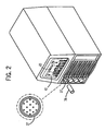
- Fig. 2 is a perspective view of the welding-type system of Fig. 1 and a detailed view of a connection port t hereon.
- Fig. 1 shows a welding-type system capable of performing various types of operations.
- the welding-type system 10 is merely representative of a wide variety of welding-type machines having various sizes, features, and ratings.
- the welding-type system as contemplated herein, can be configured to not only perform standard welding type operations such as TIG, MIG, and/or stick welding, but can also be capable of performing various cutting operations that are closely associated with the various welding procedures, such as plasma cutting for example.
- the welding-type system shown is preferably a tungsten inert gas (TIG) welding system, however, one skilled in the art will readily appreciate that it may be any related welding or cutting system, including those listed above.
- TIG tungsten inert gas
- TIG welding system 10 includes a power source 12 to condition raw power and generate a power signal suitable for welding applications.
- Power source 12 includes a processor/controller 13 that receives operational feedback and monitors the operation of TIG welding system 10.
- Connected to power source 12 is a torch 16 via a cable 18. Cable 18 provides torch 16 with power and compressed air or gas, where needed.
- Torch 16 includes a handle portion 29, or torch body, having a trigger 31 thereon to actuate the torch and work tip 32 extending therefrom.
- a work clamp 20 which is designed to connect to a workpiece (not shown) to be welded and provide a return path.
- a cable 22 designed to provide the return path for the welding current from torch 16 through the workpiece and work clamp 20.
- a power cable 24 Extending from a rear portion 23 of power source 12 is a power cable 24 having a plug 26 for connecting power source 12 to either a portable power supply (not shown) or a transmission line power receptacle (not shown).
- a gas source 33 Also connected to the power source is a gas source 33 configured to supply a gas flow to the welding torch 16.
- wireless remote control 50 and receiver 36 are included in welding-type system 10 and configured to set and adjust operational parameters therein.
- Wireless remote control 50 is located remote from the welding-type power source 12 during a welding-type operation and communicates with receiver 36 .
- Receiver 36 is operatively connected to controller 13 and welding-type power source 12 and is configured to receive and relay wireless signals from control 50 to controller 13 to process the received wireless data. In this manner, wireless remote control 50 control s operation of the welding-type system 10 and sets or adjusts the various welding-type parameters.
- receiver 36 is specially constructed to interconnect to an existing connection port 37 of welding-type system 10.
- connection p ort 37 is also configured to engage standard control cables (not shown) often used in a welding system.
- receiver 36 is constructed to engage connection port 37, older welding-type systems not capable of control via a wireless remote device can be easily modified (i.e., retrofitted) to incorporate receiver 36 and wireless remote control 50 of the current invention.
- the receiver 36 is constructed to connect to welding-type power source 12 by way of an existing 14-pin connection port 37 located on the fro nt panel 42 of power source 12.
- receiver 36 is operable with either AC or DC power, and over various control voltages, at least ranging from 5V to 24V.
- An exemplary control circuit having a wide voltage window is preferred to achieve this functionality.
- radio control (RC) signals are used.
- other means of communication can include, but are not limited to, radio frequency (RF), cellular digital packet data, high speed circuit switched data, packet data cellular, general packet radio service, radio transmission technology, Bluetooth, IrDA, multi-channel multipoint distribution service, local multipoint distr ibution service, WiMAX, 802.11 Wi-Fi, infrared, UHF, VHF, and RIM. It is recognized that the mode of communication selected will depend on the specific needs of the welding-type process and on the environment in which the process is being performed in.
- wireless remote control 50 be in the form of a foot pedal control, a handheld control, or a fingertip control; however, such embodiments are not meant to limit the form of the wireless remote control 50 that can be used in the present invention.
- a wireless remote control 50 in the form of a foot pedal control, fingertip control, or handheld control can include a switch (not shown) or other similar device thereon that allows an operator to easily adjust and control one or more welding parameters in welding-type system 10.
- These controllable welding parameters can include, but are not limited to, current, voltage, inductance, and pulse commands.
- Front panel control 42 is of a design well-known in the art, and includes a plurality of adjustors and selectors thereon. The exact mechanisms found on front panel control 42 can vary, but will allow an operator to select the specific welding parameters to be controlled by wireless remote control 50.
- a wireless remote control assembly kit (not shown) can be integrated with an existing welding-type system by operatively connecting receiver 36 with controller 13 of the welding-type power source 12 via an existing connection port 37. Wireless remote 50 is then configured to communicate with receiver 36.
- Receiver 36 is configured to receive and relay wireless signals from control 50 to the controller 13 to process the received wireless data so as to control operation of the welding-type system 10 and set or adjust the various welding-type parameters.
- welding-type systems not only includes welders, but also includes any system that requires such enclosures and/or high power outputs, such as heating and cutting systems.
- Those skilled in the art are well acqua inted with such welding-type devices, and as used herein, the term is given its ordinary meaning to those skilled in the art of welding and cutting apparatus.
- the present invention including welding -type systems, is equivalently applicable wi th any device requiring high power output, including welders, plasma cutters, induction heaters, and the like.
- Reference to welding power, welding - type power, or welders generally, includes welding, cutting, or heating power.
- Description of a welding app aratus illustrates just one embodiment in which the present invention may be implemented.
- the present invention is equivalently applicable with many high power systems, such as cutting, or any similar systems.
- a welding-type system includes a power source having a controller to regulate welding operations and a welding torch actuated by a trigger and connected to the power source.
- the system also includes a wireless remote control configured to remotely transmit a signal for controlling a plurality of welding parameters in the welding system, and a receiver remote from the wireless control and configured to receive the signal and allow the control ler to regulate at least one of the plurality of welding parameters in response thereto.
- the receiver is further configured to engage a connection port located on the power source, the connection port configured to engage both the receiver and a control c able.
- a wireless remote control kit for retrofitting a welding -type apparatus includes a wireless control configured to transmit a signal to control a plurality of welding parameters in a welding -type apparatus suitable for producing a welding -type power.
- the wireless remote control kit further includes a receiver remote from the wireless control and configured to receive and relay the signal to the welding-type apparatus. The receiver is operatively con nected to a controller housed in a power source of the welding-type apparatus.
- a method for adapting an existing welding -type system for use with a wireless remote control includes the steps of connecting a receiver to a welding-type power source by way of an existing control cable connection port, wirelessly transmitting a signal from the wireless remote control indicative of desired operational parameters of the welding -type system, receiving the signal remotely by way of the receiver, and controlling the welding -type system in accordance with data embodied in the received wirelessly transmitted signal.
Landscapes
- Engineering & Computer Science (AREA)
- Physics & Mathematics (AREA)
- Plasma & Fusion (AREA)
- Mechanical Engineering (AREA)
- Theoretical Computer Science (AREA)
- Arc Welding Control (AREA)
- Selective Calling Equipment (AREA)
Claims (5)
- Système de soudage (10), comprenant :une source d'alimentation (12) comportant une unité de commande (13) conçue pour réguler une opération de soudage, la source d'alimentation (12) comportant un point de raccordement (37) ;un chalumeau soudeur (16) raccordé à la source d'alimentation (12) ;une télécommande (50) conçue pour transmettre à distance un signal permettant de commander au moins un parmi une pluralité de paramètres de soudage dans le système de soudage (10) ; etun récepteur (36) raccordé à l'unité de commande (13) à distance de la télécommande (50) et conçu pour recevoir le signal et, en réponse à celui-ci, pour permettre à l'unité de commande (13) de réguler au moins un parmi la pluralité de paramètres de soudage ;caractérisé en ce que la télécommande (50) est sans fil, le récepteur (36) est en outre conçu pour coopérer avec le point de raccordement (37) situé sur la source d'alimentation (12), le point de raccordement (37) est conçu pour coopérer à la fois avec le récepteur (36) et un câble de commande, et le point de raccordement (37) est un connecteur à 14 broches.
- Système de soudage (10) selon la revendication 1, la pluralité de paramètres comprenant des commandes de courant, de tension, d'inductance et d'impulsions.
- Système de soudage (10) selon la revendication 1, le récepteur (36) étant raccordé de façon fonctionnelle à la source d'alimentation (12) et à l'unité de commande (13) pour relayer des signaux entre elles.
- Système de soudage (10) selon la revendication 1, la télécommande sans fil (50) communiquant avec le récepteur (36) par un des moyens suivants : radiocommande (RC), radiofréquence (RF), données par paquets numériques cellulaires, données à commutation de circuit à haut débit, système cellulaire de données par paquets, service général de radiocommunication en mode paquets, technologie de transmission radioélectrique, Bluetooth, IRDA, service de distribution multipoint multicanal, service de distribution multipoint local, WiMAX, Wi-Fi 802.11, infrarouge, UHF, VHF et RIM.
- Système de soudage (10) selon la revendication 1, la télécommande sans fil (50) étant en outre conçue pour être une commande parmi une commande de poche, une commande à pédale et une commande au toucher.
Applications Claiming Priority (2)
| Application Number | Priority Date | Filing Date | Title |
|---|---|---|---|
| US11/560,765 US9180544B2 (en) | 2006-11-16 | 2006-11-16 | Method and apparatus for wireless remote control communication of a welder |
| PCT/US2007/078983 WO2008063736A1 (fr) | 2006-11-16 | 2007-09-20 | Procédé et appareil de commande à distance sans fil des communications d'une soudeuse |
Publications (2)
| Publication Number | Publication Date |
|---|---|
| EP2081723A1 EP2081723A1 (fr) | 2009-07-29 |
| EP2081723B1 true EP2081723B1 (fr) | 2012-03-28 |
Family
ID=39232870
Family Applications (1)
| Application Number | Title | Priority Date | Filing Date |
|---|---|---|---|
| EP07842847A Revoked EP2081723B1 (fr) | 2006-11-16 | 2007-09-20 | Procédé et appareil de commande à distance sans fil des communications d'une soudeuse |
Country Status (6)
| Country | Link |
|---|---|
| US (2) | US9180544B2 (fr) |
| EP (1) | EP2081723B1 (fr) |
| CN (3) | CN105171193A (fr) |
| AT (1) | ATE551144T1 (fr) |
| CA (1) | CA2661893A1 (fr) |
| WO (1) | WO2008063736A1 (fr) |
Cited By (1)
| Publication number | Priority date | Publication date | Assignee | Title |
|---|---|---|---|---|
| US9486873B2 (en) | 2014-03-13 | 2016-11-08 | Ck Worldwide Inc. | Fingertip and foot pedal amperage control combination apparatus and method |
Families Citing this family (46)
| Publication number | Priority date | Publication date | Assignee | Title |
|---|---|---|---|---|
| WO2008022326A2 (fr) | 2006-08-18 | 2008-02-21 | Freedom Special Technologies, Inc. | Procédé et appareil permettant de commander un système de soudage autogène |
| USD599746S1 (en) | 2008-05-16 | 2009-09-08 | Freedom Special Technologies, Inc. | Foot pedal controller |
| US20110180517A1 (en) * | 2010-01-26 | 2011-07-28 | Illinois Tool Works Inc. | Methods and systems for binding a wireless control device to a welding power source |
| US9056366B2 (en) * | 2010-05-21 | 2015-06-16 | Illinois Tool Works Inc. | Welding gas leak detection system and method |
| US9993891B2 (en) * | 2010-07-14 | 2018-06-12 | Illinois Tool Works Inc. | Welding parameter control via welder motion or position monitoring |
| US20120097644A1 (en) * | 2010-10-26 | 2012-04-26 | Illinois Tool Works Inc. | Modular data over power converter for welding power supply |
| US10058948B2 (en) * | 2010-12-29 | 2018-08-28 | Illinois Tool Works Inc. | Weld cell system with communication |
| US11123814B2 (en) * | 2011-03-25 | 2021-09-21 | Illinois Tool Works Inc. | Battery powered compact wire feeder |
| AT511334B1 (de) | 2011-07-14 | 2012-11-15 | Fronius Int Gmbh | Schweissstromquelle und verfahren zu deren steuerung |
| US9789558B2 (en) | 2011-08-18 | 2017-10-17 | Illinois Tool Works Inc. | System and device operating using a welding power bus |
| US20130200055A1 (en) * | 2012-02-02 | 2013-08-08 | Lincoln Global, Inc. | Power source and wire feeder matching |
| US9270520B2 (en) | 2012-08-17 | 2016-02-23 | Illinois Tool Works Inc. | Wireless communication network sensor information for control of industrial equipment in harsh environments |
| US9712947B2 (en) | 2012-08-17 | 2017-07-18 | Illinois Tool Works Inc. | Wireless communication network improved robustness for control of industrial equipment in harsh environments |
| US10286475B2 (en) | 2012-08-17 | 2019-05-14 | Illinois Tool Works Inc. | Wireless communication network for control of industrial equipment in harsh environments |
| US9119023B2 (en) | 2012-08-17 | 2015-08-25 | Illinois Tool Works Inc. | Wireless communication network association and security for control of industrial equipment in harsh environments |
| US9449498B2 (en) | 2012-08-17 | 2016-09-20 | Illinois Tool Works Inc. | Wireless communication network power optimization for control of industrial equipment in harsh environments |
| US10118241B2 (en) | 2012-09-07 | 2018-11-06 | Illinois Tool Works Inc. | Welding system with multiple user interface modules |
| US9035219B1 (en) | 2012-10-18 | 2015-05-19 | Doug Schmidt | Arc welding machine adapted for remote controlled current adjustment |
| MX350852B (es) * | 2013-03-15 | 2017-09-19 | Illinois Tool Works | Sistemas de antena para utilizarse en las fuentes de energía para soldar y los sistemas de soldadura. |
| US20150114942A1 (en) * | 2013-10-28 | 2015-04-30 | Marc Lee Denis | System and method for data exchange and control with a wireless communication terminal on a welding system |
| US9993890B2 (en) | 2013-10-28 | 2018-06-12 | Illinois Tool Works Inc. | System and method for data exchange and control with a wireless remote control for welding systems |
| US20150174681A1 (en) * | 2013-12-23 | 2015-06-25 | Tri Tool, Inc. | Integrated Controller/Power Source for an Arc Welding Apparatus |
| US11103948B2 (en) | 2014-08-18 | 2021-08-31 | Illinois Tool Works Inc. | Systems and methods for a personally allocated interface for use in a welding system |
| CN104289836B (zh) * | 2014-10-08 | 2015-12-16 | 合肥金海康五金机械制造有限公司 | 一种多点多面焊接设备 |
| US10363627B2 (en) | 2014-12-16 | 2019-07-30 | Illinois Tool Works Inc. | Systems and methods for providing location services for a welding power supply |
| US10105785B2 (en) * | 2014-12-18 | 2018-10-23 | Illinois Tool Works Inc. | System and method for communication with welding gas line |
| US10672967B2 (en) * | 2014-12-19 | 2020-06-02 | Illinois Tool Works Inc. | Systems for energy harvesting using welding subsystems |
| US20160175965A1 (en) * | 2014-12-19 | 2016-06-23 | Illinois Tool Works Inc. | Methods and systems for harvesting weld cable energy to power welding subsystems |
| US10369652B2 (en) | 2015-07-24 | 2019-08-06 | Illinois Tool Works Inc. | Wireless and powerline communications in a welding-type system |
| US10279414B2 (en) | 2015-08-06 | 2019-05-07 | Lincoln Global, Inc. | Engine drive welder and methods and systems of controlling the same |
| US10201869B2 (en) | 2015-08-06 | 2019-02-12 | Lincoln Global, Inc. | Engine drive welder and methods and systems of controlling the same |
| CN105127623B (zh) * | 2015-08-26 | 2019-01-29 | 长治市永华机械有限公司 | 自动焊接遥控器 |
| CN105719463A (zh) * | 2016-04-01 | 2016-06-29 | 广州九红智能装备有限公司 | 一种智能装备远程控制器 |
| CN105965198A (zh) * | 2016-07-13 | 2016-09-28 | 中山鑫辉精密技术股份有限公司 | 基于无线控制的焊接机器人工作站 |
| US20180130377A1 (en) * | 2016-11-07 | 2018-05-10 | Lincoln Global, Inc. | Communication between a welding machine and a live welding training device |
| US10987749B2 (en) * | 2017-01-04 | 2021-04-27 | Illinois Tool Works Inc. | Methods and systems for indicating a schedule in a welding-type torch |
| US20180293880A1 (en) * | 2017-04-07 | 2018-10-11 | Snow EZ, LLC | Wireless remote control retrofit kit |
| CN107283027B (zh) * | 2017-08-15 | 2023-05-16 | 南京东斯达机电科技有限公司 | 一种气体保护焊机的控制系统 |
| CA3021652C (fr) * | 2017-11-29 | 2021-06-29 | Spencer Gifts Llc | Systeme et methode de controle d'accessoires animes |
| CN109570832B (zh) * | 2018-11-24 | 2020-10-30 | 上海沪工焊接集团股份有限公司 | 一种带按键焊枪操作模式的对比控制方法 |
| US11817006B2 (en) | 2019-02-19 | 2023-11-14 | Ilinois Tool Works Inc. Assignee | Weld modules for weld training systems |
| US12220774B2 (en) * | 2019-10-22 | 2025-02-11 | Illinois Tool Works Inc. | Systems and methods for multiple source control of an engine driven power system |
| US12122000B2 (en) | 2020-05-06 | 2024-10-22 | Illinois Tool Works Inc. | Wireless welding-type power supply management |
| EP3943229A1 (fr) | 2020-07-22 | 2022-01-26 | FRONIUS INTERNATIONAL GmbH | Module de communication pour une source de courant de soudage |
| US11774954B2 (en) | 2020-12-02 | 2023-10-03 | Westinghouse Electric Company Llc | Systems and methods for wireless remote control of automated equipment |
| CN115430889B (zh) * | 2022-09-20 | 2023-09-29 | 中广核工程有限公司 | 无线焊机参数配置装置 |
Family Cites Families (63)
| Publication number | Priority date | Publication date | Assignee | Title |
|---|---|---|---|---|
| US2043331A (en) * | 1934-11-26 | 1936-06-09 | J D Adams Mfg Company | Control for welding apparatus |
| US2175891A (en) * | 1935-09-26 | 1939-10-10 | Westinghouse Electric & Mfg Co | Control system |
| US2526597A (en) * | 1945-08-10 | 1950-10-17 | Winslow Paul Howard | Current control system |
| US2617913A (en) * | 1950-09-30 | 1952-11-11 | Harnischfeger Corp | Low open circuit voltage alternating current welding circuit |
| US2642515A (en) * | 1950-10-30 | 1953-06-16 | Earle W Bagg | Remote control for arc welding |
| US3567902A (en) * | 1969-04-25 | 1971-03-02 | Chemetron Corp | Arc welding power supply assembly |
| US4051344A (en) * | 1975-04-28 | 1977-09-27 | Robbins Dennis R | Remote control for an arc welding machine |
| US3992565A (en) * | 1975-07-07 | 1976-11-16 | Belden Corporation | Composite welding cable having gas ducts and switch wires therein |
| NO136138C (no) * | 1975-09-26 | 1980-12-02 | Jon Erlend Gloemmen | Anordning for fjernregulering av nettdrevne likestroem- og vekselstroem-sveisemaskiner |
| US4079231A (en) * | 1976-03-30 | 1978-03-14 | Union Carbide Corporation | Touchwork system for a MIG arc welding apparatus |
| US4147919A (en) * | 1977-01-24 | 1979-04-03 | Matasovic John L | Remote control portable wirefeed arc welding system |
| US4247752A (en) * | 1978-03-31 | 1981-01-27 | Westinghouse Electric Corp. | Constant current arc welder |
| US4216367A (en) * | 1978-04-18 | 1980-08-05 | Miller Electric Manufacturing Company | Wireless remote control for electric welder |
| US4216368A (en) * | 1978-11-27 | 1980-08-05 | Delay Calvin J | Remote control device for arc welding |
| US4227066A (en) * | 1979-02-12 | 1980-10-07 | Bulwidas Jr John J | Hand-operated remote control unit and mounting structure for an arc welding machine |
| US4467174A (en) * | 1981-02-19 | 1984-08-21 | Gilliland Malcolm T | Remote control of open circuit voltage in a welding power supply |
| US4410789A (en) * | 1981-09-09 | 1983-10-18 | Story Alan R | Remote control for welding machine amperage |
| US4521672A (en) * | 1981-10-27 | 1985-06-04 | Miller Electric Manufacturing Company | Electronic welding apparatus |
| US4450340A (en) * | 1982-12-10 | 1984-05-22 | Miller Electric Manufacturing Company | Arc welder power supply with fail-safe voltage reducing circuit |
| US4561059A (en) * | 1983-02-24 | 1985-12-24 | Beckworth Davis International, Inc. | Microprocessor controlled welding apparatus |
| US4641292A (en) * | 1983-06-20 | 1987-02-03 | George Tunnell | Voice controlled welding system |
| US4508954A (en) * | 1984-05-18 | 1985-04-02 | Oxo Welding Equipment Co., Inc. | Portable arc voltage wirefeed welding system |
| US4531045A (en) * | 1984-06-27 | 1985-07-23 | Hobart Brothers Company | Trigger hold circuit for welding power supply |
| JPS61137675A (ja) | 1984-12-10 | 1986-06-25 | Nippon Steel Corp | 自動溶接機 |
| IT1204121B (it) * | 1986-02-27 | 1989-03-01 | Cebora Spa | Torcia di saldatura o taglio al plasma con arco non trasferito |
| JPH07115183B2 (ja) * | 1988-06-29 | 1995-12-13 | 三菱電機株式会社 | 負荷電圧検出システムと該検出システムを用いたパルスアーク溶接装置並びにパルスレーザ装置及び表面処理装置 |
| DE3925100A1 (de) * | 1989-07-28 | 1991-01-31 | Trw Nelson Bolzenschweiss Tech | Elektrisches bolzenschweissgeraet |
| JPH0616948B2 (ja) | 1990-10-26 | 1994-03-09 | デンヨー株式会社 | エンジン溶接機の遠隔制御方法 |
| JPH0616946B2 (ja) | 1990-10-26 | 1994-03-09 | デンヨー株式会社 | エンジン溶接機の遠隔制御方法並びにその装置 |
| FI91497B (fi) | 1992-06-15 | 1994-03-31 | Kemppi Oy | Laitteisto ja menetelmä hitsauskoneen virtalähteen ja/tai apulaitteiden säätämiseksi radiotaajuisilla signaaleilla |
| US5406050A (en) * | 1992-10-08 | 1995-04-11 | Advanced Fusion Technologies, Inc. | Multiple operator welding apparatus |
| US5276305A (en) * | 1992-12-09 | 1994-01-04 | Industrial Technology Research Institute | Remote control setting device for electric welding machines |
| US5708253A (en) * | 1995-06-07 | 1998-01-13 | Hill Technical Services, Inc. | Apparatus and method for computerized interactive control, measurement and documentation of arc welding |
| GB9800405D0 (en) * | 1998-01-10 | 1998-03-04 | Reed Edward John | Welding method and apparatus |
| US6040555A (en) * | 1998-02-20 | 2000-03-21 | Illinois Tool Works Inc. | Remote control for welders and method therefor |
| US6156999A (en) * | 1998-12-28 | 2000-12-05 | Plasma-Laser Technologies Ltd. | Method and device for welding arc ignition for arc welding apparatus |
| AT406942B (de) * | 1999-01-15 | 2000-10-25 | Fronius Schweissmasch | Fernreglereinheit für ein schweissgerät oder eine stromquelle |
| US6114657A (en) * | 1999-04-01 | 2000-09-05 | Illinois Tool Works Inc. | Method and apparatus for welding with a trigger hold |
| US6103994A (en) * | 1999-04-12 | 2000-08-15 | Illinois Tool Works | Welding device with remote device detection |
| AT409238B (de) | 1999-11-05 | 2002-06-25 | Fronius Schweissmasch Prod | Festlegen und/oder feststellen von benutzerberechtigungen mittels eines transponders,einer fingerabdruckerkennung oder dergleichen |
| US6512199B1 (en) * | 1999-12-20 | 2003-01-28 | Anthony M. Blazina | Constant-speed motor-driven modular welding apparatus with electronic power control apparatus, electrode holder operation controls, and safety interlock |
| FR2803233B1 (fr) | 2000-01-03 | 2002-03-29 | Air Liquide | Dispositif de commande a distance sans fil d'une installation de travail a l'arc electrique |
| AT412389B (de) * | 2000-12-11 | 2005-02-25 | Fronius Int Gmbh | System zur durchführung eines schweissprozesses |
| US6624388B1 (en) * | 2001-01-25 | 2003-09-23 | The Lincoln Electric Company | System and method providing distributed welding architecture |
| US6531673B2 (en) * | 2001-04-09 | 2003-03-11 | Michael R. Fedorcak | Apparatus to control output of a welding machine |
| US7245875B2 (en) * | 2001-04-24 | 2007-07-17 | Lincoln Global, Inc. | System and method to facilitate wireless communication in a welding environment |
| JP2003088957A (ja) | 2001-09-18 | 2003-03-25 | Daihen Corp | 消耗電極式アーク溶接装置 |
| US6504131B1 (en) * | 2001-09-19 | 2003-01-07 | Illinois Tool Works Inc. | Welding-type power supply with boot loader |
| US6841752B2 (en) * | 2001-10-02 | 2005-01-11 | Joseph J. Ward | Wire feed speed adjustable welding torch |
| JP2003154455A (ja) | 2001-11-21 | 2003-05-27 | Daihen Corp | 消耗電極式アーク溶接装置 |
| JP4739621B2 (ja) | 2001-12-25 | 2011-08-03 | 株式会社ダイヘン | 消耗電極式アーク溶接装置 |
| JP4777589B2 (ja) | 2002-02-19 | 2011-09-21 | 株式会社ダイヘン | 非消耗電極式アーク溶接装置 |
| US20030184515A1 (en) * | 2002-04-02 | 2003-10-02 | Huo-Lu Tsai | Computer user input assembly with wired and wireless transmission capability |
| US6909285B2 (en) * | 2002-09-11 | 2005-06-21 | Visteon Global Technologies, Inc. | Method for detecting failure of a relay |
| US7205503B2 (en) * | 2003-07-24 | 2007-04-17 | Illinois Tool Works Inc. | Remotely controlled welding machine |
| CN1282099C (zh) | 2003-09-25 | 2006-10-25 | 联想(北京)有限公司 | 计算机外围装置及其工作方法 |
| US6906285B2 (en) * | 2003-10-24 | 2005-06-14 | Lincoln Global, Inc. | Remote wire feeder |
| US20050155068A1 (en) * | 2004-01-08 | 2005-07-14 | Chang Chung L. | Multi-media player |
| US7294808B2 (en) * | 2004-03-15 | 2007-11-13 | Lincoln Global, Inc. | Remote wire feeder |
| US7381922B2 (en) * | 2004-10-27 | 2008-06-03 | Illinois Tool Works Inc. | Method and apparatus for remotely controlling a welding system |
| US7772524B2 (en) * | 2005-01-21 | 2010-08-10 | Lincoln Global, Inc. | Integrating sensors over a digital link |
| US7336259B2 (en) * | 2005-04-11 | 2008-02-26 | Kye Systems Corp. | Rechargeable wireless input device |
| CN1746833A (zh) | 2005-09-29 | 2006-03-15 | 上海序参量科技发展有限公司 | 显示型鼠标 |
-
2006
- 2006-11-16 US US11/560,765 patent/US9180544B2/en active Active
-
2007
- 2007-09-20 CN CN201510552481.1A patent/CN105171193A/zh active Pending
- 2007-09-20 WO PCT/US2007/078983 patent/WO2008063736A1/fr not_active Ceased
- 2007-09-20 CN CNA2007800341201A patent/CN101516562A/zh active Pending
- 2007-09-20 AT AT07842847T patent/ATE551144T1/de active
- 2007-09-20 EP EP07842847A patent/EP2081723B1/fr not_active Revoked
- 2007-09-20 CA CA002661893A patent/CA2661893A1/fr not_active Abandoned
- 2007-09-20 CN CN201910749955.XA patent/CN110788445A/zh active Pending
-
2015
- 2015-10-19 US US14/886,533 patent/US11148220B2/en active Active
Cited By (1)
| Publication number | Priority date | Publication date | Assignee | Title |
|---|---|---|---|---|
| US9486873B2 (en) | 2014-03-13 | 2016-11-08 | Ck Worldwide Inc. | Fingertip and foot pedal amperage control combination apparatus and method |
Also Published As
| Publication number | Publication date |
|---|---|
| US20160039035A1 (en) | 2016-02-11 |
| CA2661893A1 (fr) | 2008-05-29 |
| EP2081723A1 (fr) | 2009-07-29 |
| CN110788445A (zh) | 2020-02-14 |
| WO2008063736A1 (fr) | 2008-05-29 |
| US9180544B2 (en) | 2015-11-10 |
| US11148220B2 (en) | 2021-10-19 |
| US20080116185A1 (en) | 2008-05-22 |
| ATE551144T1 (de) | 2012-04-15 |
| CN105171193A (zh) | 2015-12-23 |
| CN101516562A (zh) | 2009-08-26 |
Similar Documents
| Publication | Publication Date | Title |
|---|---|---|
| EP2081723B1 (fr) | Procédé et appareil de commande à distance sans fil des communications d'une soudeuse | |
| US8785817B2 (en) | Method and apparatus for wireless remote control communication of a welder | |
| US10758994B2 (en) | Weld cable communications controller module | |
| EP1986811B1 (fr) | Un système type soudage avec une source de puissance et une commande à distance connecté à l'aide d'un cable de soudage utilisant une modulation par déplacement de phase pour transmettre des commandes au travers du cable | |
| US20190344371A1 (en) | Wireless and powerline communications in a welding-type system | |
| CN100376351C (zh) | 用于在焊接装置中设定参数的方法 | |
| US20120097644A1 (en) | Modular data over power converter for welding power supply | |
| US20060086706A1 (en) | Method and apparatus for remotely controlling a welding system | |
| CN102821903A (zh) | 采用内部以太网通信的焊接系统和方法 | |
| US20160311046A1 (en) | Wireless control of a welding machine |
Legal Events
| Date | Code | Title | Description |
|---|---|---|---|
| PUAI | Public reference made under article 153(3) epc to a published international application that has entered the european phase |
Free format text: ORIGINAL CODE: 0009012 |
|
| 17P | Request for examination filed |
Effective date: 20090603 |
|
| AK | Designated contracting states |
Kind code of ref document: A1 Designated state(s): AT BE BG CH CY CZ DE DK EE ES FI FR GB GR HU IE IS IT LI LT LU LV MC MT NL PL PT RO SE SI SK TR |
|
| DAX | Request for extension of the european patent (deleted) | ||
| 17Q | First examination report despatched |
Effective date: 20101115 |
|
| GRAP | Despatch of communication of intention to grant a patent |
Free format text: ORIGINAL CODE: EPIDOSNIGR1 |
|
| GRAS | Grant fee paid |
Free format text: ORIGINAL CODE: EPIDOSNIGR3 |
|
| GRAA | (expected) grant |
Free format text: ORIGINAL CODE: 0009210 |
|
| AK | Designated contracting states |
Kind code of ref document: B1 Designated state(s): AT BE BG CH CY CZ DE DK EE ES FI FR GB GR HU IE IS IT LI LT LU LV MC MT NL PL PT RO SE SI SK TR |
|
| REG | Reference to a national code |
Ref country code: GB Ref legal event code: FG4D |
|
| REG | Reference to a national code |
Ref country code: CH Ref legal event code: EP |
|
| REG | Reference to a national code |
Ref country code: AT Ref legal event code: REF Ref document number: 551144 Country of ref document: AT Kind code of ref document: T Effective date: 20120415 |
|
| REG | Reference to a national code |
Ref country code: IE Ref legal event code: FG4D |
|
| REG | Reference to a national code |
Ref country code: DE Ref legal event code: R096 Ref document number: 602007021678 Country of ref document: DE Effective date: 20120524 |
|
| REG | Reference to a national code |
Ref country code: NL Ref legal event code: VDEP Effective date: 20120328 |
|
| PG25 | Lapsed in a contracting state [announced via postgrant information from national office to epo] |
Ref country code: LT Free format text: LAPSE BECAUSE OF FAILURE TO SUBMIT A TRANSLATION OF THE DESCRIPTION OR TO PAY THE FEE WITHIN THE PRESCRIBED TIME-LIMIT Effective date: 20120328 |
|
| LTIE | Lt: invalidation of european patent or patent extension |
Effective date: 20120328 |
|
| PG25 | Lapsed in a contracting state [announced via postgrant information from national office to epo] |
Ref country code: LV Free format text: LAPSE BECAUSE OF FAILURE TO SUBMIT A TRANSLATION OF THE DESCRIPTION OR TO PAY THE FEE WITHIN THE PRESCRIBED TIME-LIMIT Effective date: 20120328 Ref country code: FI Free format text: LAPSE BECAUSE OF FAILURE TO SUBMIT A TRANSLATION OF THE DESCRIPTION OR TO PAY THE FEE WITHIN THE PRESCRIBED TIME-LIMIT Effective date: 20120328 Ref country code: GR Free format text: LAPSE BECAUSE OF FAILURE TO SUBMIT A TRANSLATION OF THE DESCRIPTION OR TO PAY THE FEE WITHIN THE PRESCRIBED TIME-LIMIT Effective date: 20120629 |
|
| REG | Reference to a national code |
Ref country code: AT Ref legal event code: MK05 Ref document number: 551144 Country of ref document: AT Kind code of ref document: T Effective date: 20120328 |
|
| PG25 | Lapsed in a contracting state [announced via postgrant information from national office to epo] |
Ref country code: CY Free format text: LAPSE BECAUSE OF FAILURE TO SUBMIT A TRANSLATION OF THE DESCRIPTION OR TO PAY THE FEE WITHIN THE PRESCRIBED TIME-LIMIT Effective date: 20120328 |
|
| PG25 | Lapsed in a contracting state [announced via postgrant information from national office to epo] |
Ref country code: BE Free format text: LAPSE BECAUSE OF FAILURE TO SUBMIT A TRANSLATION OF THE DESCRIPTION OR TO PAY THE FEE WITHIN THE PRESCRIBED TIME-LIMIT Effective date: 20120328 Ref country code: IS Free format text: LAPSE BECAUSE OF FAILURE TO SUBMIT A TRANSLATION OF THE DESCRIPTION OR TO PAY THE FEE WITHIN THE PRESCRIBED TIME-LIMIT Effective date: 20120728 Ref country code: SE Free format text: LAPSE BECAUSE OF FAILURE TO SUBMIT A TRANSLATION OF THE DESCRIPTION OR TO PAY THE FEE WITHIN THE PRESCRIBED TIME-LIMIT Effective date: 20120328 Ref country code: RO Free format text: LAPSE BECAUSE OF FAILURE TO SUBMIT A TRANSLATION OF THE DESCRIPTION OR TO PAY THE FEE WITHIN THE PRESCRIBED TIME-LIMIT Effective date: 20120328 Ref country code: CZ Free format text: LAPSE BECAUSE OF FAILURE TO SUBMIT A TRANSLATION OF THE DESCRIPTION OR TO PAY THE FEE WITHIN THE PRESCRIBED TIME-LIMIT Effective date: 20120328 Ref country code: EE Free format text: LAPSE BECAUSE OF FAILURE TO SUBMIT A TRANSLATION OF THE DESCRIPTION OR TO PAY THE FEE WITHIN THE PRESCRIBED TIME-LIMIT Effective date: 20120328 Ref country code: SI Free format text: LAPSE BECAUSE OF FAILURE TO SUBMIT A TRANSLATION OF THE DESCRIPTION OR TO PAY THE FEE WITHIN THE PRESCRIBED TIME-LIMIT Effective date: 20120328 Ref country code: PL Free format text: LAPSE BECAUSE OF FAILURE TO SUBMIT A TRANSLATION OF THE DESCRIPTION OR TO PAY THE FEE WITHIN THE PRESCRIBED TIME-LIMIT Effective date: 20120328 |
|
| PG25 | Lapsed in a contracting state [announced via postgrant information from national office to epo] |
Ref country code: PT Free format text: LAPSE BECAUSE OF FAILURE TO SUBMIT A TRANSLATION OF THE DESCRIPTION OR TO PAY THE FEE WITHIN THE PRESCRIBED TIME-LIMIT Effective date: 20120730 Ref country code: SK Free format text: LAPSE BECAUSE OF FAILURE TO SUBMIT A TRANSLATION OF THE DESCRIPTION OR TO PAY THE FEE WITHIN THE PRESCRIBED TIME-LIMIT Effective date: 20120328 |
|
| PLBI | Opposition filed |
Free format text: ORIGINAL CODE: 0009260 |
|
| PG25 | Lapsed in a contracting state [announced via postgrant information from national office to epo] |
Ref country code: DK Free format text: LAPSE BECAUSE OF FAILURE TO SUBMIT A TRANSLATION OF THE DESCRIPTION OR TO PAY THE FEE WITHIN THE PRESCRIBED TIME-LIMIT Effective date: 20120328 Ref country code: AT Free format text: LAPSE BECAUSE OF FAILURE TO SUBMIT A TRANSLATION OF THE DESCRIPTION OR TO PAY THE FEE WITHIN THE PRESCRIBED TIME-LIMIT Effective date: 20120328 Ref country code: NL Free format text: LAPSE BECAUSE OF FAILURE TO SUBMIT A TRANSLATION OF THE DESCRIPTION OR TO PAY THE FEE WITHIN THE PRESCRIBED TIME-LIMIT Effective date: 20120328 |
|
| PLAX | Notice of opposition and request to file observation + time limit sent |
Free format text: ORIGINAL CODE: EPIDOSNOBS2 |
|
| 26 | Opposition filed |
Opponent name: FRONIUS INTERNATIONAL GMBH Effective date: 20121228 |
|
| REG | Reference to a national code |
Ref country code: DE Ref legal event code: R026 Ref document number: 602007021678 Country of ref document: DE Effective date: 20121228 |
|
| PG25 | Lapsed in a contracting state [announced via postgrant information from national office to epo] |
Ref country code: MC Free format text: LAPSE BECAUSE OF NON-PAYMENT OF DUE FEES Effective date: 20120930 Ref country code: ES Free format text: LAPSE BECAUSE OF FAILURE TO SUBMIT A TRANSLATION OF THE DESCRIPTION OR TO PAY THE FEE WITHIN THE PRESCRIBED TIME-LIMIT Effective date: 20120709 |
|
| REG | Reference to a national code |
Ref country code: CH Ref legal event code: PL |
|
| PLBB | Reply of patent proprietor to notice(s) of opposition received |
Free format text: ORIGINAL CODE: EPIDOSNOBS3 |
|
| REG | Reference to a national code |
Ref country code: IE Ref legal event code: MM4A |
|
| PG25 | Lapsed in a contracting state [announced via postgrant information from national office to epo] |
Ref country code: BG Free format text: LAPSE BECAUSE OF FAILURE TO SUBMIT A TRANSLATION OF THE DESCRIPTION OR TO PAY THE FEE WITHIN THE PRESCRIBED TIME-LIMIT Effective date: 20120628 Ref country code: LI Free format text: LAPSE BECAUSE OF NON-PAYMENT OF DUE FEES Effective date: 20120930 Ref country code: CH Free format text: LAPSE BECAUSE OF NON-PAYMENT OF DUE FEES Effective date: 20120930 Ref country code: IE Free format text: LAPSE BECAUSE OF NON-PAYMENT OF DUE FEES Effective date: 20120920 |
|
| PG25 | Lapsed in a contracting state [announced via postgrant information from national office to epo] |
Ref country code: MT Free format text: LAPSE BECAUSE OF FAILURE TO SUBMIT A TRANSLATION OF THE DESCRIPTION OR TO PAY THE FEE WITHIN THE PRESCRIBED TIME-LIMIT Effective date: 20120328 |
|
| RAP2 | Party data changed (patent owner data changed or rights of a patent transferred) |
Owner name: ILLINOIS TOOL WORKS INC. |
|
| PG25 | Lapsed in a contracting state [announced via postgrant information from national office to epo] |
Ref country code: TR Free format text: LAPSE BECAUSE OF FAILURE TO SUBMIT A TRANSLATION OF THE DESCRIPTION OR TO PAY THE FEE WITHIN THE PRESCRIBED TIME-LIMIT Effective date: 20120328 |
|
| PG25 | Lapsed in a contracting state [announced via postgrant information from national office to epo] |
Ref country code: LU Free format text: LAPSE BECAUSE OF NON-PAYMENT OF DUE FEES Effective date: 20120920 |
|
| PG25 | Lapsed in a contracting state [announced via postgrant information from national office to epo] |
Ref country code: HU Free format text: LAPSE BECAUSE OF FAILURE TO SUBMIT A TRANSLATION OF THE DESCRIPTION OR TO PAY THE FEE WITHIN THE PRESCRIBED TIME-LIMIT Effective date: 20070920 |
|
| RDAF | Communication despatched that patent is revoked |
Free format text: ORIGINAL CODE: EPIDOSNREV1 |
|
| APBM | Appeal reference recorded |
Free format text: ORIGINAL CODE: EPIDOSNREFNO |
|
| APBP | Date of receipt of notice of appeal recorded |
Free format text: ORIGINAL CODE: EPIDOSNNOA2O |
|
| APAH | Appeal reference modified |
Free format text: ORIGINAL CODE: EPIDOSCREFNO |
|
| APBQ | Date of receipt of statement of grounds of appeal recorded |
Free format text: ORIGINAL CODE: EPIDOSNNOA3O |
|
| APAH | Appeal reference modified |
Free format text: ORIGINAL CODE: EPIDOSCREFNO |
|
| APAH | Appeal reference modified |
Free format text: ORIGINAL CODE: EPIDOSCREFNO |
|
| REG | Reference to a national code |
Ref country code: FR Ref legal event code: PLFP Year of fee payment: 9 |
|
| PGFP | Annual fee paid to national office [announced via postgrant information from national office to epo] |
Ref country code: GB Payment date: 20150928 Year of fee payment: 9 |
|
| PGFP | Annual fee paid to national office [announced via postgrant information from national office to epo] |
Ref country code: FR Payment date: 20150917 Year of fee payment: 9 |
|
| GBPC | Gb: european patent ceased through non-payment of renewal fee |
Effective date: 20160920 |
|
| REG | Reference to a national code |
Ref country code: FR Ref legal event code: ST Effective date: 20170531 |
|
| PG25 | Lapsed in a contracting state [announced via postgrant information from national office to epo] |
Ref country code: FR Free format text: LAPSE BECAUSE OF NON-PAYMENT OF DUE FEES Effective date: 20160930 Ref country code: GB Free format text: LAPSE BECAUSE OF NON-PAYMENT OF DUE FEES Effective date: 20160920 |
|
| REG | Reference to a national code |
Ref country code: DE Ref legal event code: R064 Ref document number: 602007021678 Country of ref document: DE Ref country code: DE Ref legal event code: R103 Ref document number: 602007021678 Country of ref document: DE |
|
| APBU | Appeal procedure closed |
Free format text: ORIGINAL CODE: EPIDOSNNOA9O |
|
| PGFP | Annual fee paid to national office [announced via postgrant information from national office to epo] |
Ref country code: IT Payment date: 20180920 Year of fee payment: 12 Ref country code: DE Payment date: 20180927 Year of fee payment: 12 |
|
| RDAG | Patent revoked |
Free format text: ORIGINAL CODE: 0009271 |
|
| STAA | Information on the status of an ep patent application or granted ep patent |
Free format text: STATUS: PATENT REVOKED |
|
| 27W | Patent revoked |
Effective date: 20181005 |
|
| P01 | Opt-out of the competence of the unified patent court (upc) registered |
Effective date: 20230606 |