EP2081788B1 - Procédé de fonctionnement en toute sécurité d'un véhicule hybride hydraulique - Google Patents
Procédé de fonctionnement en toute sécurité d'un véhicule hybride hydraulique Download PDFInfo
- Publication number
- EP2081788B1 EP2081788B1 EP07854173A EP07854173A EP2081788B1 EP 2081788 B1 EP2081788 B1 EP 2081788B1 EP 07854173 A EP07854173 A EP 07854173A EP 07854173 A EP07854173 A EP 07854173A EP 2081788 B1 EP2081788 B1 EP 2081788B1
- Authority
- EP
- European Patent Office
- Prior art keywords
- motor
- pressure fluid
- vehicle
- displacement
- fluid
- Prior art date
- Legal status (The legal status is an assumption and is not a legal conclusion. Google has not performed a legal analysis and makes no representation as to the accuracy of the status listed.)
- Not-in-force
Links
Images




Classifications
-
- B—PERFORMING OPERATIONS; TRANSPORTING
- B60—VEHICLES IN GENERAL
- B60K—ARRANGEMENT OR MOUNTING OF PROPULSION UNITS OR OF TRANSMISSIONS IN VEHICLES; ARRANGEMENT OR MOUNTING OF PLURAL DIVERSE PRIME-MOVERS IN VEHICLES; AUXILIARY DRIVES FOR VEHICLES; INSTRUMENTATION OR DASHBOARDS FOR VEHICLES; ARRANGEMENTS IN CONNECTION WITH COOLING, AIR INTAKE, GAS EXHAUST OR FUEL SUPPLY OF PROPULSION UNITS IN VEHICLES
- B60K6/00—Arrangement or mounting of plural diverse prime-movers for mutual or common propulsion, e.g. hybrid propulsion systems comprising electric motors and internal combustion engines
- B60K6/08—Prime-movers comprising combustion engines and mechanical or fluid energy storing means
- B60K6/12—Prime-movers comprising combustion engines and mechanical or fluid energy storing means by means of a chargeable fluidic accumulator
-
- B—PERFORMING OPERATIONS; TRANSPORTING
- B60—VEHICLES IN GENERAL
- B60W—CONJOINT CONTROL OF VEHICLE SUB-UNITS OF DIFFERENT TYPE OR DIFFERENT FUNCTION; CONTROL SYSTEMS SPECIALLY ADAPTED FOR HYBRID VEHICLES; ROAD VEHICLE DRIVE CONTROL SYSTEMS FOR PURPOSES NOT RELATED TO THE CONTROL OF A PARTICULAR SUB-UNIT
- B60W30/00—Purposes of road vehicle drive control systems not related to the control of a particular sub-unit, e.g. of systems using conjoint control of vehicle sub-units
- B60W30/18—Propelling the vehicle
- B60W30/18009—Propelling the vehicle related to particular drive situations
- B60W30/18027—Drive off, accelerating from standstill
-
- B—PERFORMING OPERATIONS; TRANSPORTING
- B60—VEHICLES IN GENERAL
- B60W—CONJOINT CONTROL OF VEHICLE SUB-UNITS OF DIFFERENT TYPE OR DIFFERENT FUNCTION; CONTROL SYSTEMS SPECIALLY ADAPTED FOR HYBRID VEHICLES; ROAD VEHICLE DRIVE CONTROL SYSTEMS FOR PURPOSES NOT RELATED TO THE CONTROL OF A PARTICULAR SUB-UNIT
- B60W30/00—Purposes of road vehicle drive control systems not related to the control of a particular sub-unit, e.g. of systems using conjoint control of vehicle sub-units
- B60W30/18—Propelling the vehicle
- B60W30/18009—Propelling the vehicle related to particular drive situations
- B60W30/18054—Propelling the vehicle related to particular drive situations at stand still, e.g. engine in idling state
-
- F—MECHANICAL ENGINEERING; LIGHTING; HEATING; WEAPONS; BLASTING
- F16—ENGINEERING ELEMENTS AND UNITS; GENERAL MEASURES FOR PRODUCING AND MAINTAINING EFFECTIVE FUNCTIONING OF MACHINES OR INSTALLATIONS; THERMAL INSULATION IN GENERAL
- F16H—GEARING
- F16H61/00—Control functions within control units of change-speed- or reversing-gearings for conveying rotary motion ; Control of exclusively fluid gearing, friction gearing, gearings with endless flexible members or other particular types of gearing
- F16H61/38—Control of exclusively fluid gearing
- F16H61/40—Control of exclusively fluid gearing hydrostatic
- F16H61/4078—Fluid exchange between hydrostatic circuits and external sources or consumers
- F16H61/4096—Fluid exchange between hydrostatic circuits and external sources or consumers with pressure accumulators
-
- F—MECHANICAL ENGINEERING; LIGHTING; HEATING; WEAPONS; BLASTING
- F16—ENGINEERING ELEMENTS AND UNITS; GENERAL MEASURES FOR PRODUCING AND MAINTAINING EFFECTIVE FUNCTIONING OF MACHINES OR INSTALLATIONS; THERMAL INSULATION IN GENERAL
- F16H—GEARING
- F16H61/00—Control functions within control units of change-speed- or reversing-gearings for conveying rotary motion ; Control of exclusively fluid gearing, friction gearing, gearings with endless flexible members or other particular types of gearing
- F16H61/38—Control of exclusively fluid gearing
- F16H61/40—Control of exclusively fluid gearing hydrostatic
- F16H61/4192—Detecting malfunction or potential malfunction, e.g. fail safe
-
- B—PERFORMING OPERATIONS; TRANSPORTING
- B60—VEHICLES IN GENERAL
- B60K—ARRANGEMENT OR MOUNTING OF PROPULSION UNITS OR OF TRANSMISSIONS IN VEHICLES; ARRANGEMENT OR MOUNTING OF PLURAL DIVERSE PRIME-MOVERS IN VEHICLES; AUXILIARY DRIVES FOR VEHICLES; INSTRUMENTATION OR DASHBOARDS FOR VEHICLES; ARRANGEMENTS IN CONNECTION WITH COOLING, AIR INTAKE, GAS EXHAUST OR FUEL SUPPLY OF PROPULSION UNITS IN VEHICLES
- B60K6/00—Arrangement or mounting of plural diverse prime-movers for mutual or common propulsion, e.g. hybrid propulsion systems comprising electric motors and internal combustion engines
- B60K6/08—Prime-movers comprising combustion engines and mechanical or fluid energy storing means
- B60K6/12—Prime-movers comprising combustion engines and mechanical or fluid energy storing means by means of a chargeable fluidic accumulator
- B60K2006/126—Prime-movers comprising combustion engines and mechanical or fluid energy storing means by means of a chargeable fluidic accumulator the hydraulic accumulator starts the engine
-
- B—PERFORMING OPERATIONS; TRANSPORTING
- B60—VEHICLES IN GENERAL
- B60L—PROPULSION OF ELECTRICALLY-PROPELLED VEHICLES; SUPPLYING ELECTRIC POWER FOR AUXILIARY EQUIPMENT OF ELECTRICALLY-PROPELLED VEHICLES; ELECTRODYNAMIC BRAKE SYSTEMS FOR VEHICLES IN GENERAL; MAGNETIC SUSPENSION OR LEVITATION FOR VEHICLES; MONITORING OPERATING VARIABLES OF ELECTRICALLY-PROPELLED VEHICLES; ELECTRIC SAFETY DEVICES FOR ELECTRICALLY-PROPELLED VEHICLES
- B60L2240/00—Control parameters of input or output; Target parameters
- B60L2240/40—Drive Train control parameters
- B60L2240/48—Drive Train control parameters related to transmissions
- B60L2240/486—Operating parameters
-
- B—PERFORMING OPERATIONS; TRANSPORTING
- B60—VEHICLES IN GENERAL
- B60W—CONJOINT CONTROL OF VEHICLE SUB-UNITS OF DIFFERENT TYPE OR DIFFERENT FUNCTION; CONTROL SYSTEMS SPECIALLY ADAPTED FOR HYBRID VEHICLES; ROAD VEHICLE DRIVE CONTROL SYSTEMS FOR PURPOSES NOT RELATED TO THE CONTROL OF A PARTICULAR SUB-UNIT
- B60W2540/00—Input parameters relating to occupants
- B60W2540/10—Accelerator pedal position
-
- B—PERFORMING OPERATIONS; TRANSPORTING
- B60—VEHICLES IN GENERAL
- B60W—CONJOINT CONTROL OF VEHICLE SUB-UNITS OF DIFFERENT TYPE OR DIFFERENT FUNCTION; CONTROL SYSTEMS SPECIALLY ADAPTED FOR HYBRID VEHICLES; ROAD VEHICLE DRIVE CONTROL SYSTEMS FOR PURPOSES NOT RELATED TO THE CONTROL OF A PARTICULAR SUB-UNIT
- B60W2540/00—Input parameters relating to occupants
- B60W2540/12—Brake pedal position
-
- B—PERFORMING OPERATIONS; TRANSPORTING
- B60—VEHICLES IN GENERAL
- B60W—CONJOINT CONTROL OF VEHICLE SUB-UNITS OF DIFFERENT TYPE OR DIFFERENT FUNCTION; CONTROL SYSTEMS SPECIALLY ADAPTED FOR HYBRID VEHICLES; ROAD VEHICLE DRIVE CONTROL SYSTEMS FOR PURPOSES NOT RELATED TO THE CONTROL OF A PARTICULAR SUB-UNIT
- B60W2540/00—Input parameters relating to occupants
- B60W2540/16—Ratio selector position
-
- F—MECHANICAL ENGINEERING; LIGHTING; HEATING; WEAPONS; BLASTING
- F16—ENGINEERING ELEMENTS AND UNITS; GENERAL MEASURES FOR PRODUCING AND MAINTAINING EFFECTIVE FUNCTIONING OF MACHINES OR INSTALLATIONS; THERMAL INSULATION IN GENERAL
- F16H—GEARING
- F16H2312/00—Driving activities
- F16H2312/20—Start-up or shut-down
-
- Y—GENERAL TAGGING OF NEW TECHNOLOGICAL DEVELOPMENTS; GENERAL TAGGING OF CROSS-SECTIONAL TECHNOLOGIES SPANNING OVER SEVERAL SECTIONS OF THE IPC; TECHNICAL SUBJECTS COVERED BY FORMER USPC CROSS-REFERENCE ART COLLECTIONS [XRACs] AND DIGESTS
- Y02—TECHNOLOGIES OR APPLICATIONS FOR MITIGATION OR ADAPTATION AGAINST CLIMATE CHANGE
- Y02T—CLIMATE CHANGE MITIGATION TECHNOLOGIES RELATED TO TRANSPORTATION
- Y02T10/00—Road transport of goods or passengers
- Y02T10/60—Other road transportation technologies with climate change mitigation effect
- Y02T10/62—Hybrid vehicles
Definitions
- the present disclosure is directed to processes for safe operation of a hydraulic hybrid vehicle system, and in particular, to processes for detecting and/or addressing safety conditions arising out of operation of the vehicle.
- hybrid is used in reference to vehicles employing two or more power sources to provide motive energy to the vehicle.
- electric hybrid vehicles are currently available that employ an internal combustion engine and a generator which generates electricity that can be stored in a battery of storage cells. This stored energy is then used, as necessary, to drive an electric motor coupled to the drive train of the vehicle.
- Hybrid vehicles may be grouped into two general classes, namely, parallel hybrid and series hybrid vehicles.
- Parallel hybrid vehicles are vehicles employing a more or less typical engine, transmission, and drive train, with additional components providing a second power path for the vehicle.
- the engine of a vehicle is used to generate surplus energy during periods when the vehicle is cruising at a steady speed, or otherwise demanding less than the engine is capable of providing when operating at its most efficient load. The surplus energy is then stored for future use.
- Hybrid electric vehicles that are currently available generally operate according to the scheme broadly outlined above, utilizing a generator to add load to the engine and convert the excess power to electricity for storage in the battery, and later utilizing the battery and an electric motor to supplement the conventional drivetrain when more power to the wheels is required than can be efficiently produced by the engine alone.
- Series hybrid vehicles in contrast to the parallel hybrid model, have no direct mechanical drivetrain between the engine and the drive wheels of the vehicle. They do not employ a drive shaft as described with reference to parallel hybrid vehicles.
- power from an engine is converted directly to a form that can be used by a secondary drive motor to power the vehicle, and that is also conducive to efficient storage
- the engine can be operated at its most efficient load and speed without regard to variations in the speed of the vehicle.
- a series hybrid vehicle may operate for extended periods with the engine shut down, operating on stored energy alone.
- Series hybrid vehicles are potentially more efficient than parallel hybrids because of the greater freedom to control engine operation for maximum efficiency, and because of the elimination of the mechanical drivetrain linking the engine to the wheels, thereby reducing the net weight of the vehicle, as compared to a parallel hybrid vehicle.
- US 2006/00659 A1 relates to a wheel creep control of a hydraulic hybrid vehicle using regenerative braking.
- the displacement of a hydraulic pump/motor is increased to require slightly more torque than the torque produced by an idling engine driving a torque converter of an automatic transmission.
- safety processes are provided for detecting and addressing a number of conditions that do or might arise in the operation of a hydraulic hybrid vehicle system.
- the disclosed embodiments include an initialization procedure for start-up of a hydraulic hybrid vehicle, as well as a shut-down procedure. Additionally, procedures for detecting and responding to failure of a motor, internal and external fluid leaks, and non-responsive actuation and mode control systems are provided.
- FIG. 2-7 is a flow diagram illustrating a process related to safe operation of a hydraulic system such as that illustrated in Figure 1 , according to an embodiment of the invention.
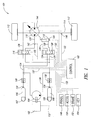
- FIG. 1 is a simplified schematic diagram of a hydraulic hybrid vehicle system 100.
- the vehicle 100 includes an internal combustion engine (ICE) 102 whose output shaft is coupled to a hydraulic pump 104.
- the pump 104 is configured to draw low-pressure fluid from a low-pressure accumulator 106 (LPA) and pump the fluid at high pressure to a high-pressure accumulator 108 (HPA).
- LPA low-pressure accumulator
- HPA high-pressure accumulator 108
- the high-pressure fluid is used to drive one or more hydraulic pump-motor(s) (hereafter motor ) 110, which in turn applies torque to drive wheels 112 via axles 114 and a differential (not shown).
- a transmission is also provided.
- the pump 104 is shown as a fixed-displacement pump, but it may be a variable displacement pump, in which case the load on the engine can be modified by changing the displacement of the pump. Additionally, the pump 104 may be a pump/motor to permit the use of the pump 104 as a motor to start the engine by fluid pressure.
- the motor 110 of the embodiment described is a positive-angle pump/motor, i.e., capable of stroking from zero to a positive stroke angle.
- the motor may alternatively be an over-center pump/motor, capable of stroking to both positive and negative stroke angles.
- a stroke angle of greater than zero this is to be construed as meaning an absolute value greater than zero, i.e., either in a negative or positive direction.
- the fluid circuit will be arranged differently than shown in Figure 1 to accommodate an over-center motor. Nevertheless, it is within the abilities of one of ordinary skill in the art to adapt the embodiments described hereafter for use with an over-center motor.
- U.S. Patent Application No. 2008/0080985 filed on September 29, 2006 provides details of an over-center fluid circuit. Other circuits are known in the art.
- the LPA and HPA are pre-charged with gas cells 107, 109, respectively, that are compressed as fluid is pumped into the respective accumulator.
- the pressure of the compressed gas provides the motive force for the hydraulic operation of the vehicle system 100.
- a mode valve 116 is provided to control polarity of the fluid to the motor 110, and an actuator 118 is coupled to the motor 110 to control displacement.
- a control valve 120 controls operation of the actuator 118.
- Low-pressure fluid lines 124 couple the LPA 106 to the pump 104 and the valves 116, 120, while high-pressure fluid lines 126 couple the HPA 108 to the pump 104 and the valves 116,120.
- Motor fluid supply lines 128 couple the mode valve 116 to the motor 110, and actuator fluid supply lines 130 couple the control valve 120 to the actuator 118.
- the mode valve 116 is shown as a three-position valve. In a first position, the valve 116 places a first fluid port of the motor 110 in fluid communication with the high pressure fluid supply while placing a second fluid port of the motor 110 in fluid communication with the low-pressure fluid supply. In this configuration, the motor 110 applies a forward torque to the drive wheels 112, tending to drive the vehicle forward. In a second position, the valve 116 places the first fluid port of the motor 110 in fluid communication with the low-pressure fluid supply 106 while placing the second fluid port of the motor 110 in fluid communication with the high-pressure fluid supply 108. In this configuration, the motor 110 applies a reverse torque to the drive wheels 112, tending to drive the vehicle 100 in reverse. In a third position, the valve 116 places the first fluid port in fluid communication with the second fluid port, creating a closed loop, in which condition the motor 110 is free to rotate, but does not receive any motive power.
- the control valve 120 is also shown as a three position valve, and the actuator is shown as a double action (push-pull) actuator.
- the control valve 120 places a first fluid chamber of the actuator 118 in fluid communication with the HPA 108 while placing a second fluid chamber of the actuator 118 in fluid communication with the LPA 106. In this position, the motor 110 is stroked toward a maximum displacement, which will increase the power output of the motor 110.
- the control valve 120 places the first fluid chamber of the actuator 118 in fluid communication with the LPA 106 while placing the second fluid chamber of the actuator 118 in fluid communication with the HPA 108. In this position, the motor 110 is stroked toward a minimum displacement, decreasing the power output of the motor 110.
- the control valve 120 closes the actuator supply lines 130, hydraulically locking the actuator 118 in place and holding the displacement of the motor 110 at a constant value.
- a number of sensors are provided to monitor various aspects of the operation of the vehicle 100. These include sensors 134, 136 coupled to the high- and low-pressure accumulators 108, 106, respectively, configured to measure fluid pressure and flow rate; rotation sensors 146 (only one of which is shown) for measuring rotation speed of the wheels 112; position sensor 156 for determining the stroke angle of the motor 110; pressure sensor 144 for measuring a fluid pressure inside the casing of the motor 110, and another (not shown) for measuring a fluid pressure inside the casing of the pump; flow sensor 142 positioned in one of the motor fluid supply lines 128; shift indicator sensor (PRNDL) 148 for detecting a position of a shift indicator; accelerator position sensor (APS) 150 for monitoring a position of an accelerator pedal; brake position sensor (BPS) 152 for monitoring a position of a brake pedal; and key position sensor (KPS) 154. Additionally, the ICE 102 is provided with a typical suite of engine sensors (not shown separately) such as are commonly employed in modern vehicles, such as, for example
- Either or both of the accumulators 106, 108 may include a "fuse" valve (not shown) configured to close if a maximum flow rate value is exceeded.
- a "fuse" valve (not shown) configured to close if a maximum flow rate value is exceeded.
- Any or all of the check valves 138, 140, the flow rate sensors 134, 136, and the fuse valves may be integrated, and may be located in or on the respective accumulators 108, 106.
- the position sensor 156 is shown coupled to the actuator 118, though the position sensor 156 may instead be positioned at or in the motor 110. According to an embodiment, there may be more than one position sensor 156, as will be explained later in this disclosure.
- the shift indicator sensor 148 detects a position of a shift indicator via which a driver selects a mode of vehicle operation from among a number of choices such as, for example, P (park), R (reverse), N (neutral), D (drive), and L (low, in those embodiments that include a transmission and/or one or more additional motors).
- the sensors may provide data to the control unit by any of a number of mediums, including digital or analog electrical signals, hydraulic or pneumatic pressure, mechanical linkage, etc. Accordingly, the control lines 132 are shown merely to indicate an operative connection, and are not intended to suggest the nature of the connection.
- the ICE 102 drives the pump 104, which pumps fluid at high-pressure into the HPA 108.
- the control unit 122 monitors the fluid pressure in the HPA and controls the operation of the ICE 102 to maintain the fluid pressure within an acceptable range.
- Pressurized fluid from the HPA 108 is utilized to control the displacement of the motor 110 and to power the motor 110 to apply torque to the drive wheels 112.
- the vehicle 100 is also configured to employ regenerative braking.
- the mode valve 116 When the vehicle is traveling forward, and the operator applies the brake, the mode valve 116 is moved to its second position, which, as described above, causes the motor 110 to apply torque in the reverse direction.
- the amount of reverse torque is controlled by the displacement of the motor 110, which in turn is controlled by the amount of pressure (or depression) applied by the operator on the brake pedal.
- the motor 110 Because of the forward motion of the vehicle 100, the motor 110 continues rotation in the forward direction, even though it is applying torque in the reverse direction.
- the motor 110 operates as a pump, drawing fluid from the LPA 106 and pumping the fluid at high pressure to the HPA 108. This creates drag on the rotation of the axles 114, which is transferred to the drive wheels 112, slowing the vehicle 100.
- a driver turns a key or otherwise selects start-up of the vehicle 100.
- the control unit 122 is powered up, the KPS detects the start-up command, and the control unit initializes the system.
- the shift indicator indicates a forward "gear" or position
- the control unit 122 controls the mode valve 116 and the control valve 120 according to a position of the accelerator pedal or brake pedal.
- the mode valve 116 is moved to the first position, applying fluid pressure to the motor 110, and the control valve 118 is controlled to increase displacement of the motor, converting fluid pressure to torque to accelerate the vehicle.
- hybrid vehicles With the advent of hybrid vehicles, there are many previously unknown situations that might arise, for which a typical driver may be unprepared.
- the inventor has recognized that to the extent a hybrid vehicle can be made to interact with a driver in a manner that is substantially similar to a conventional vehicle, the driver will be better equipped to react appropriately to everyday occurrences, as well as most emergencies.
- control elements such as sensors and the control unit
- descriptions of the other embodiments of the invention may not specifically recite a particular sensor as performing a described function, but one of ordinary skill in the art will recognize disclosed elements that could be employed to fulfill the function, and will also recognize a number of alternative configurations that could be adapted to operate in particular applications, given the relevant design considerations.
- the functions described with reference to the control unit may be performed by a single unit such as a microprocessor or the like, may be broken up among a number of elements, or may be part of the operation of an element or elements configured to perform other tasks.
- step 202 the driver turns the key or otherwise starts initialization of the vehicle's operation system.
- the control unit confirms that the shift selector is in either park or neutral (204). If not, i.e., if the shift selector is in one of the forward settings or the reverse setting, the driver is notified of the cause for a non-start (214), and no further action is taken. If the shift selector is in the Park or Neutral position, the control unit confirms that the mode valve 116 is in the neutral position (206), and, if so, that the motor 110 is set at zero displacement (208). If the motor 110 is set at zero displacement, the high-pressure valve 138 is opened (210), and normal operation of the vehicle is enabled (212).
- the high-pressure valve is opened (228), and the motor is commanded to a displacement of zero (230).
- the displacement is again checked (232), and if the motor 110 has moved to a displacement of zero, the system is enabled for normal operation (212). If the motor 110 has not moved to a zero displacement, the high-pressure valve 138 is closed, and the operator is alerted to a critical system fault (CSF) condition (240), i.e., that the system is inoperative and in need of repair or service before the vehicle can be operated.
- CSF critical system fault
- a CSF condition is signaled to an operator
- this may be as basic as a light or other indicator on the vehicle instrument panel, in combination with the vehicle system shutting down, or the signal may provide more detailed information such as the nature of the fault, the defective component, or the type of service required.
- the control unit attempts to confirm that the motor displacement is at zero (216). If the motor displacement is not at zero, the system signals a CSF to the driver (218). If the motor displacement is confirmed to be at zero at step 216, the high-pressure valve 138 is opened (220), and the mode valve is commanded to neutral (222). Again, the position of the mode valve is checked. If it has moved to neutral, the system is enabled for normal operation (212). If the mode valve has not moved to neutral, the high-pressure valve 138 is closed, and the operator is alerted to a CSF condition (226).
- the time required to move through the process outlined above may be in the range of a few hundred milliseconds to as much as a second, but, with regard to the operator's perception, it can be performed almost instantaneously, so that the operator can "start" the vehicle and drive away without any perceived delay.
- the control unit may also be programmed to slave the throttle control of the ICE to the accelerator pedal to permit revving of the ICE during start-up and before the shift selector is moved away from the P or N positions, for reasons similar to those previously mentioned (as used here, the term throttle, e.g., throttle control, or throttle position, refers to the fuel rate of the ICE).
- throttle e.g., throttle control, or throttle position
- Figure 3 outlines a check process 300 for the low-pressure side of the hydraulic circuit of the vehicle, according to one embodiment.
- the low-pressure valve 140 is opened (302), which permits fluid to flow from the LPA 106 into the system. Fluid flow from the LPA is then measured (304) and compared to a threshold value (306). If there is a fluid flow that exceeds the threshold, the pressure valve 140 is closed and the operator is alerted to a CSF condition (308). If, on the other hand, any fluid flow is below the threshold, the system can proceed with opening the high-pressure valve 138 in accordance with one of the steps outlined with reference to Figure 2 , such as for example, at step 210.
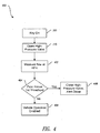
- Figure 4 illustrates a similar process for checking the high-pressure side of the fluid circuit.
- the high-pressure valve 138 is opened, such as at step 210, 220, or 228 of Figure 2 , which permits fluid to flow from the HPA 108 into the system. Fluid flow at the HPA is then measured (402) and compared to a threshold value (404). If there is a fluid flow that exceeds the threshold, the high-pressure valve 138 is closed and the operator is alerted to a CSF condition (406). If fluid flow is below the threshold, operation of the system is enabled, at least with respect to the concerns addressed in the process of Figure 4 (408).
- measuring flow of high-pressure fluid into the system may detect leaks, including leaks out of the system.
- leaks including leaks out of the system.
- the fluid flow at the HPA will be equal to the flow at the LPA, and any difference in flow between the HPA and the LPA indicates a loss of fluid from the system, i.e., a leak outside the system.
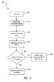
- This process is outlined in Figure 5 .
- the key is turned on (202) and the high-pressure valve is opened (210)
- the fluid flow at the LPA is measured (502).
- the flow at the HPA is measured (504).
- the high-pressure accumulator flow (HPAF) is compared to the low-pressure accumulator flow (LPAF) (506). If an absolute value of the difference between the HPAF and the LPAF exceeds a threshold, the system closes the high-pressure valve and alerts the driver of a leak outside the system (508). If the difference does not exceed the threshold, the system is enabled for start-up (510).
- FIG. 6 another process 600 is provided for detecting excessive external or internal leaking of a hydraulic vehicle system such as that described with reference to Figure 1 , during normal operation of the vehicle.
- Fluid flow at the HPA is measured (602).
- a HPA flow value is calculated, based upon operating characteristics of the motor 110 and/or pump 104 (604), and compared with the measured fluid flow. The difference between the calculated value and the measured value represents the amount of fluid that is leaking past components in the system.
- Steps 608-616 will hereafter be referred to collectively as an auto shut-down procedure.
- An excessively high internal leakage rate is indicative of internal damage to a pump or valve. Performing the auto shut-down helps prevent or limit further damage to the system that might occur as a result of continued operation.
- the auto-shutdown procedure 620 is performed in situations where a potentially dangerous situation may exist and operation of the vehicle must be terminated to prevent danger to the occupants of the vehicle, severe damage to the system, or danger to other vehicles on the road.
- a high-pressure fluid leak outside the system such as would be detected by one or more of the processes of Figures 4-6 , if the leak is not detected, the high pressures in the system can very quickly turn a minor leak into a very large one.
- the system may have 10-20 gallons of hydraulic fluid, which is generally some type of oil.
- the hydraulic lines and valves that supply fluid from the accumulators 106, 108 to the motor 110 are designed to accommodate a flow of more than 100 gallons per minute (gpm) at pressures exceeding 4,000 psi. If, for example, a hose fitting were to burst, the entire fluid contents of the system could be deposited on the road behind the vehicle in less than ten seconds. Such a volume of oil being poured unexpectedly on a highway could create a hazardous situation.
- the actuator 118 is powered by hydraulic pressure.
- either or both of the mode valve 116 and the actuator control valve 120 are also operated by hydraulic pressure. If either the displacement actuator 118 can be moved to zero, or the mode valve 116 can be moved to neutral, the motor 110 will rotate freely, without power, allowing the vehicle to coast. By commanding the motor 110 to zero displacement and the mode to neutral before the HPA valve 138 is closed, fluid pressure in the system can be used to perform the commands.
- closing the HPA valve 138 before shutting down the ICE may cause the pump 104 to hydraulically lock, producing very high pressure, or the motor 110 to suddenly exert a higher output torque, depending, in part, on the exact circuit arrangement and the positions of other valves in the system. Either outcome could damage components of the system and create a dangerous driving condition. This can be avoided by shutting down the ICE prior to closing the HPA valve.
- a process 700 is provided for monitoring the displacement control of the motor 110.
- the actual motor displacement (AMD) of the motor 110 is measured, then compared to the commanded motor displacement (CMD) (704). If an absolute value of the difference between AMD and CMD does not exceed a first threshold (TD) (704), the process loops back to step 702. If the difference exceeds the first threshold, but not a second threshold (706), the operator is notified of a non-critical system fault (NSF) at step 716, but the process loops to step 702 and the system continues in operation (this process up through step 706 may also apply to pump 104 if its displacement is variable).
- NSF non-critical system fault
- the motor 110 is commanded to zero displacement (708) and a new comparison is made to determine if, following the new command, the difference is now below the first threshold (710) or the second threshold (712). If, following the new command, the difference is below the first threshold, the process loops to step 702. If the difference is below the second threshold (712), the operator is notified of a NSF at step 716 and the process loops to step 702. If, after the new command, the difference still exceeds the second threshold, mode valve 116 is commanded to neutral (718). At step 720, the actual mode valve position (AMVP) of the mode valve 116 is measured, then compared to the neutral position (722).
- AMVP actual mode valve position
- the AMD is compared to a third displacement threshold (724) and, if the AMD is less than the third threshold, the operator is notified of a NSF at step 716 and the process loops to step 702. If the AMVP does not return to neutral or the AMD is greater than the third threshold, an auto-shutdown is performed (620) and the operator is notified of a CSF at step 726. In one alternate embodiment, steps 706, 708, and 710 are eliminated, and mode valve 116 is commanded to neutral (718) based on an initial determination at step 712 that the difference exceeds the second threshold.
- a NSF signal may simply consist of a light or other indicator on the vehicle instrument panel indicating that service is required, or the signal may include more information regarding the nature of the fault.
- control unit is programmed to rapidly pulse the valve 120 in place of or in addition to the step of moving the displacement to zero, at step 708.
- the pulsing may serve to free contaminants from the valve or actuator and permit the system to return to normal operation.
- two sensors 156 are provided, each configured to detect the displacement position of the motor 110. If the two sensors disagree as to the displacement of the motor, data from each is compared to the commanded displacement, and the sensor that disagrees with the commanded displacement is ignored. The driver is notified of a NSF, but the system continues in otherwise normal operation. If, on the other hand, the two sensors agree with each other, but disagree with the commanded displacement, the process outlined in Figure 7 is followed.
- a parallel displacement control valve is provided, such that, in the event of a stuck displacement determination by a process such as that illustrated in Figure 7 , the control valve 120 is removed from the circuit (by a shut-off valve), and the parallel control valve is activated to supply high- and low-pressure fluid to the actuator 118.
- the driver is notified of a NSF, while the system remains operational.
- a process is provided for monitoring the condition of the gas cells 107, 109 of the LPA 106 and the HPA 108, respectively. It will be recognized that as high-pressure fluid flows into or out of the HPA 108, the pressure within that accumulator will change accordingly. Likewise, as low-pressure fluid flows into or out of the LPA 106, the pressure within that accumulator will also change accordingly. In a closed system, such as that described with reference to Figure 1 , if fluid flows out of one accumulator, it must flow into the other at the same rate.
- a fault condition exists, indicating either a loss of fluid from the system or a loss of pressure. If the loss of pressure is due to gas leaking from the gas cell 109 of the HPA 108, the pressure will rise at the LPA 106, and will actually be greater than what would be predicted, given the pressure at the HPA 108, so that the sum of the pressures of the HPA and LPA is actually higher than expected. Thus, such a gas leak can be distinguished from a fluid leak by the excessive rise in pressure of the LPA.
- the escaping gas will remain in the LPA or become entrained in the fluid of the system, which may not result in a change of pressure, but will cause increased compressibility of the fluid, resulting in slower responses and reduced efficiency of the system. If the indicated leakage exceeds a first threshold, but is less than a second threshold, a NSF is indicated, and if the leakage exceeds the second threshold, an auto shut-down is performed and the operator is notified of a CSF.
- the control valve 120 is configured to move the actuator 118 to zero the displacement of the motor 110 in the event power to the valve is lost.
- this may be accomplished in a number of ways.
- one or more springs may be provided that will move the valve to the second position, unless some other force exerts an opposing force.
- the opposing force is provided by the control unit, via a pilot valve, a solenoid, or other control means.
- the springs will immediately move the control valve to the second position, zeroing the motor.
- the mode valve 116 is configured to place the motor in an unpowered condition in the event of a loss of power to the valve. Thus, if power is lost to the valve for any reason, power is removed from the motor, preventing uncontrolled power to the motor. This may involve a valve having a spring configured to drive the valve to the neutral position if power is lost.
- fluid pressure is monitored within the motor and pump casings.
- fluid inside the casing is vented to the low-pressure side of the system. In this way, fluid that inevitably leaks past the pistons and seals of the machine is returned to the low-pressure fluid supply.
- the pressure sensor in the event of a machine failure in which a large quantity of high-pressure fluid escapes to the casing, the pressure sensor will detect a rise in pressure, and the control unit will execute an auto shut-down, or at the least, shut off high pressure to the machine.
- additional motors are incorporated, either alongside the first motor, or coupled to another pair of drive wheels.
- the inoperative motor in the event of a system failure that results in the inoperability of a motor, the inoperative motor is shut-out, while one or more remaining motors can operate in a "limp home" mode to permit the vehicle to operate at reduced capacity to avoid complete shut-down.
- system failures may include loss of displacement control, internal and external leaks in the fluid circuit of one or another motor, and other motor failures.
- the isolation of the inoperative motor can be accomplished by placing its respective mode valve in neutral, and commanding the motor to a zero displacement.
- the steps 718 and 720 are of particular use in systems employing more than one hydraulic motor. If the mode valve can be confirmed to be in its neutral position, the associated motor can be isolated from the system by the mode valve, without completely shutting down the system.
- isolation valves are provided, configured to separately isolate each of the motors so that, regardless of the type of failure, one motor can be completely isolated from the system while allowing the system to operate with the remaining motor(s).
- Vehicles employing more than one motor for operation are described in a number of references, including the following references: U.S. Patent No. 6,718,080 ; and U.S. Patent No. 7,374,005 ; and U.S. Patent application No. 11/233,822 .
- a process is provided for controlling the regenerative braking system.
- the control unit controls the motor to apply a reverse torque to the wheels, as described above.
- the controller decreases the displacement of the motor to reduce the braking torque.
- the friction brakes always remain operative such that if additional braking is required, a slight increase in pressure on the brake pedal engages the friction brakes.
- this serves to clean the brake rotors of debris and rust so they remain fully functional in the event of a loss of power to the motor, so that the driver always has brakes available. Additionally, if rotation sensors 146 coupled to the drive wheels 112 detect a significant difference in rotation of the wheels, indicating that a wheel is slipping, either while accelerating or braking, displacement to the motor is momentarily reduced to allow the slipping wheel to regain traction.
- features are provided that increase safety while the vehicle is stopped or being shut-down by the driver. For example, if the vehicle is traveling below a threshold speed of between around 1-5 mph, and if the shift indicator is in a moving position (i.e., D, L, or R), displacement of the motor 110 is controlled to a slight positive value such that when the vehicle is stopped, the driver must apply brakes to prevent the vehicle from creeping forward (or backward, if in reverse). This will tend to remind the driver to move the shift indicator to the P position.
- the shift indicator is moved to the P or N positions, the ICE is started, regardless of the state of charge of the HPA.
- the running engine serves to remind the driver that the vehicle is still under power, and that the key must be moved to the "off' position.
- the shift indicator must be moved to the P position before the key can be removed from the slot, again reminding the driver to fully shut-down the vehicle.
- a pressure sensor is provided in the driver's seat. If the driver leaves the seat without turning off the key, or placing the shift indicator in P, an alarm is sounded to alert the driver to the omission.
- key should be construed broadly to include any mechanism configured to enable and/or disable operation of the vehicle, including switches or buttons, remote devices, etc.
- the system When the key is moved to the Off position, the system shuts down in a manner similar to an auto shut-down as described with reference to Figure 6 .
- the motor is commanded to zero displacement; the mode valve is commanded to neutral; the ICE is shut down, the HPA valve is closed; the LPA valve is closed; and finally the control unit shuts down.
- High-pressure remaining in the system will gradually leak past seals and pistons to the low pressure side, until the pressure in the entire system is about equal to the LPA.
- the system includes a pressure relief valve that is opened after the HPA and LPA valves are closed, which vents pressure from the high-pressure side to the low-pressure side.
- some parameter of the system is measured.
- the term measure is not limited to actually obtaining a value for comparison or calculation.
- the process described with reference to Figure 7 includes measuring the actual displacement of the motor 110. While some systems may be configured to provide a true displacement value, there are many alternative solutions that are acceptable.
- a yoke of the motor is rotated through an arc, and displacement of the motor is commonly described in terms of stroke angle of the yoke. At a stroke angle of zero, the displacement is also zero, while as the angle increases, so too does the displacement, in a precisely known relationship.
- the displacement of the motor can be accurately inferred from the value of the transducer signal.
- the control signal provided by the control unit to command the displacement of the motor may be nothing more than a voltage signal of a value that corresponds to the commanded displacement.
- the steps of measuring and comparing can be performed continuously by an electrical circuit configured to condition one or both of the voltage signals, from the transducer and the control unit, so that, if the actual displacement is equal to the commanded displacement, the values of the signals are equal, then continuously comparing the values, and outputting a fault signal if a difference between the values exceeds a reference value.
- the displacement volume of the motor is not measured, in a narrow sense of the term, nor is such a value compared with a commanded displacement volume. Nevertheless, such a configuration would be considered to perform the steps outlined, and thus fall within the scope of the invention.
- measurement of other parameters, and performance of other processes may be performed inferentially.
- the process described with reference to Figure 6 includes measuring a flow rate at the HPA, and comparing the measured rate with a flow determined by the motor displacement and rotation. It is well known that it is much simpler and more economical to measure pressure of a fluid than flow. It is also known that a flow rate can be determined by measuring a difference in pressure at two points in a fluid transmission line, if pressure drop characteristics of the line are known.
- the flow of fluid between the sensors can be determined, and compared to the flow indicated by the displacement and rpm of the motor as outlined in Figure 6 . if the values disagree, a fault exists in the circuit. Additional pressure sensors at other points in the fluid circuit can be used to determine fluid flow rates in other branches, confirming, for example, that all the fluid flowing from the HPA is flowing into the LPA, as described with reference to Figure 5 .
- a claim recites a step that is to be performed following the performance of a prior, conditional, step
- the claim is to be construed to mean that the following step is not to be performed unless the conditions under which the prior step is to be performed are met.
- the claim recites a step that is to be performed prior to a conditional step
- the claim is to be construed to mean that the conditional step is not to be performed unless the conditions under which the conditional step is to be performed are met after the prior step is performed.
- CSF critical system fault
- non-critical system fault is used in the claims to refer to a condition under which the system to which the term is applied can remain in operation, but may require service.
Landscapes
- Engineering & Computer Science (AREA)
- Mechanical Engineering (AREA)
- General Engineering & Computer Science (AREA)
- Transportation (AREA)
- Automation & Control Theory (AREA)
- Chemical & Material Sciences (AREA)
- Combustion & Propulsion (AREA)
- Electric Propulsion And Braking For Vehicles (AREA)
- Control Of Positive-Displacement Pumps (AREA)
- Arrangement Or Mounting Of Propulsion Units For Vehicles (AREA)
- Hybrid Electric Vehicles (AREA)
- Control Of Transmission Device (AREA)
Claims (12)
- Un procédé d'initialisation d'un système de véhicule hybride hydraulique (100), comportant:La signalisation de l'initialisation du système (202);la vérification d'une position d'une valve de mode (116) du système (206);caractérisé en ce que le procédé comporte en outre:la vérification du réglage du débit d'un moteur hydraulique (110) du système (208, 216);le couplage d'une alimentation hydraulique haute pression (108) au système (210, 220, 228) si la valve de mode (116) est dans une position neutre et que le débit est réglé sur zéro (210), ou lorsque la valve de mode (116) est dans une position neutre (228) ou que le réglage du débit est sur zéro (220) ; etl'activation du fonctionnement du véhicule (212) à la suite du couplage si la valve de mode (116) est dans une position neutre et que le débit est réglé sur zéro.
- Le procédé de la revendication 1, comportant:La commande de la valve de mode (116) sur une position neutre (222) à la suite de l' étape de couplage (220) si la valve de mode n'est pas à une position neutre;une nouvelle vérification de la position de la valve de mode (116) à la suite de l' exécution de l'étape de commande (224);le découplage de l'alimentation hydraulique haute pression (108) du système et la génération d'un signal de défaut système critique au conducteur (226) si, après l' exécution de l'étape de commande (222) et l'étape de nouvelle vérification (224), la valve de mode (116) n'est pas dans la position neutre; etdans lequel l'étape d'activation comporte l'activation du fonctionnement du véhicule (212) si, après l' exécution de l'étape de commande (222) et l'étape de nouvelle vérification (224), la valve de mode (116) est dans une position neutre et que le débit est réglé sur zéro.
- Le procédé de la revendication 1, comportant:la commande du débit à zéro (230) après l'exécution de l'étape de couplage (228) si le débit n'est pas réglé sur zéro;une nouvelle vérification du débit du moteur hydraulique (232) après l'exécution de l'étape de commande (230);le découplage du système sur le fluide haute pression et la génération d'un signal au conducteur d'un défaut critique du système (240) si, après l'exécution de l'étape de commande (230) et l'étape de nouvelle vérification (232), le débit n'est pas réglé sur zéro ; etdans lequel l'étape d'activation comporte l'activation du fonctionnement du véhicule (212) si, après l'exécution de l'étape de commande (230) et de l'étape de nouvelle vérification (232), la valve de mode (116) est dans une position neutre et que le débit est réglé sur zéro.
- Le procédé de la revendication 1, dans lequel l'opération d'activation (212) fait directement suite à l'étape de couplage (210), si la valve de mode (116) est dans une position neutre et le débit est réglé sur zéro avant l'exécution de ladite étape de couplage (210).
- Le procédé de la revendication 1, comportant:la vérification d'une position d'un sélecteur de vitesse (204) après l'étape de signalisation (202) et avant l'exécution de l'étape de couplage (210, 220, 228); etl'annulation de l'étape d'activation et la signalisation d'un défaut de position de sélecteur de vitesse (214) si le sélecteur de vitesse n'est pas en position parking ou en position neutre.
- Le procédé de la revendication 1, comportant:La commande, pendant qu'un sélecteur de vitesse est en position autre que Parking ou Neutre, du débit du moteur hydraulique (110), au moins partiellement, en fonction de la position d'une pédale d'accélérateur; etLa commande à zéro du débit du moteur (110) pendant que le sélecteur de vitesse est en position parking ou en position neutre.
- Le procédé de la revendication 6, comportant:la démarrage, si un moteur à combustion interne (102) ne fonctionne pas déjà, du moteur à combustion interne (102) lorsque le sélecteur de vitesse est déplacé à la position parking ; etle fonctionnement du moteur à combustion interne (102) pendant que le sélecteur de vitesse est en position parking et le fonctionnement du véhicule est activé.
- Le procédé de la revendication 1, comportant, après l'étape de signalisation (202) et avant l'étape de couplage (210, 220, 228):le couplage (302) du système à une alimentation hydraulique basse pression (106) ;la comparaison d' un écoulement de fluide à basse pression dans le système avec une première valeur seuil (306);et l'annulation de l'étape de couplage, et la découplage du système sur le fluide à basse pression et la génération d' un signal au conducteur de défaut système critique (308) si l'écoulement du fluide à basse pression dépasse la première valeur seuil.
- Le procédé de la revendication 8, comportant:la comparaison de l'écoulement du fluide basse pression au sein du système à une seconde valeur seuil, inférieure que la première valeur seuil; etla génération d' un signal au conducteur de défaut système non-critique si l'écoulement du fluide à basse pression dépasse la seconde valeur seuil mais pas la première valeur seuil.
- Le procédé de la revendication 1, comportant, après l'étape de couplage (210, 220, 228) et avant l'étape d'activation (212, 408):la comparaison d' un écoulement du fluide haute pression au sein du système avec une valeur seuil (404); etl'annulation de l'étape d'activation et le découplage du système de l'alimentation hydraulique haute pression et la génération d'un signal au conducteur de défaut système critique (406) si l'écoulement du fluide à haute pression dépasse la valeur seuil.
- Le procédé de la revendication 1, comportant, avant l'étape d'activation:le couplage du système à une alimentation hydraulique basse pression (106);après les étapes de couplage, la mesure d' un écoulement de fluide à l'alimentation hydraulique basse pression (502);la mesure d'un écoulement de fluide à l'alimentation hydraulique haute pression (504) ;la comparaison d' une valeur de référence avec la valeur absolue d'une différence entre l'écoulement mesuré à l'alimentation hydraulique basse pression et l'écoulement mesuré à l'alimentation hydraulique haute pression (506);et le découplage du système de l'alimentation hydraulique haute pression (108) si la valeur absolue dépasse la valeur de référence (508).
- La méthode de la revendication 11, comportant la génération d'un signal de défaut système critique après l'exécution de l'étape de découplage (508).
Applications Claiming Priority (2)
| Application Number | Priority Date | Filing Date | Title |
|---|---|---|---|
| US11/583,205 US8118132B2 (en) | 2006-10-18 | 2006-10-18 | Hydraulic hybrid vehicle method of safe operation |
| PCT/US2007/081794 WO2008049064A2 (fr) | 2006-10-18 | 2007-10-18 | Procédé de fonctionnement en toute sécurité d'un véhicule hybride hydraulique |
Publications (2)
| Publication Number | Publication Date |
|---|---|
| EP2081788A2 EP2081788A2 (fr) | 2009-07-29 |
| EP2081788B1 true EP2081788B1 (fr) | 2011-08-31 |
Family
ID=39110875
Family Applications (1)
| Application Number | Title | Priority Date | Filing Date |
|---|---|---|---|
| EP07854173A Not-in-force EP2081788B1 (fr) | 2006-10-18 | 2007-10-18 | Procédé de fonctionnement en toute sécurité d'un véhicule hybride hydraulique |
Country Status (7)
| Country | Link |
|---|---|
| US (2) | US8118132B2 (fr) |
| EP (1) | EP2081788B1 (fr) |
| JP (1) | JP5031034B2 (fr) |
| CN (1) | CN101600592A (fr) |
| AT (1) | ATE522388T1 (fr) |
| BR (1) | BRPI0717598A2 (fr) |
| WO (1) | WO2008049064A2 (fr) |
Cited By (1)
| Publication number | Priority date | Publication date | Assignee | Title |
|---|---|---|---|---|
| WO2019034317A1 (fr) * | 2017-08-17 | 2019-02-21 | Sunfab Hydraulics Ab | Dispositif de commande pour moteur de système hydraulique |
Families Citing this family (75)
| Publication number | Priority date | Publication date | Assignee | Title |
|---|---|---|---|---|
| US8079437B2 (en) | 2008-11-17 | 2011-12-20 | Allan Rosman | Hybrid hydraulic drive system with accumulator as the frame of vehicle |
| DE102008061350A1 (de) * | 2008-12-10 | 2010-06-17 | Robert Bosch Gmbh | Hydrostatisches System mit einem hydropneumatischen Speicher |
| DE102009001357A1 (de) * | 2009-03-05 | 2010-09-09 | Robert Bosch Gmbh | Verfahren zum Betreiben eines Hydraulikhybridfahrzeugs |
| JP5682016B2 (ja) * | 2009-06-11 | 2015-03-11 | イートン コーポレーションEaton Corporation | ハイブリッド駆動システムにおける故障検知及び故障軽減 |
| SE0901362A1 (sv) * | 2009-10-21 | 2011-04-22 | Christer Thorell | Styra reglerbar effekt till/från en rotors axlar, individuellt |
| US20110198141A1 (en) * | 2010-02-16 | 2011-08-18 | Genie Industries, Inc. | Hydraulic electric hybrid drivetrain |
| FR2956841B1 (fr) * | 2010-02-26 | 2012-06-08 | Assistive Robotic Technologies | Dispositif de propulsion d'un vehicule avec recuperation et restitution d'energie |
| US9032723B2 (en) * | 2010-03-09 | 2015-05-19 | The United States Of America, As Represented By The Administrator Of The U.S. Environmental Protection Agency | Hydraulic hybrid vehicle with safe and efficient hydrostatic operation |
| DE102010012975A1 (de) * | 2010-03-22 | 2011-09-22 | Hydac Technology Gmbh | Hydrostatisches Hybrid-Antriebssystem |
| US9346347B2 (en) * | 2010-04-21 | 2016-05-24 | The United States Of America, As Represented By The Administrator Of The U.S. Environmental Protection Agency | Methods for safe operation of hydraulic hybrid vehicles with over-center pump/motors |
| CN101920722B (zh) * | 2010-07-16 | 2013-07-17 | 徐工集团工程机械股份有限公司江苏徐州工程机械研究院 | 并联式液压混合动力车辆转矩控制方法 |
| FR2964914B1 (fr) * | 2010-09-16 | 2013-04-12 | Peugeot Citroen Automobiles Sa | Chaine de traction pour vehicule hybride |
| FR2971013B1 (fr) | 2011-01-27 | 2013-02-15 | Peugeot Citroen Automobiles Sa | Procede de controle d'un moteur de recharge entrainant une pompe hydraulique |
| FR2971023B1 (fr) * | 2011-01-31 | 2014-07-11 | Poclain Hydraulics Ind | Dispositif de transmission hydraulique permettant la recuperation d'energie |
| FR2972682B1 (fr) * | 2011-03-15 | 2013-08-23 | Peugeot Citroen Automobiles Sa | Systeme de motorisation hydraulique pour vehicule automobile |
| US9285944B1 (en) | 2011-04-22 | 2016-03-15 | Angel A. Penilla | Methods and systems for defining custom vehicle user interface configurations and cloud services for managing applications for the user interface and learned setting functions |
| US10217160B2 (en) | 2012-04-22 | 2019-02-26 | Emerging Automotive, Llc | Methods and systems for processing charge availability and route paths for obtaining charge for electric vehicles |
| US9123035B2 (en) | 2011-04-22 | 2015-09-01 | Angel A. Penilla | Electric vehicle (EV) range extending charge systems, distributed networks of charge kiosks, and charge locating mobile apps |
| CN103547742B (zh) * | 2011-05-18 | 2016-09-14 | 日立建机株式会社 | 作业机械 |
| CN103620193B (zh) * | 2011-06-23 | 2015-11-25 | 丰田自动车株式会社 | 车辆的驱动控制装置 |
| US10186094B2 (en) | 2011-07-26 | 2019-01-22 | Gogoro Inc. | Apparatus, method and article for providing locations of power storage device collection, charging and distribution machines |
| JP5758051B2 (ja) | 2011-07-26 | 2015-08-05 | ゴゴロ インク | 車両の電力蓄積デバイスを物理的に保障する装置、方法、および物品 |
| WO2013016538A2 (fr) | 2011-07-26 | 2013-01-31 | Gogoro, Inc. | Gestion thermique d'éléments constitutifs dans des véhicules à moteur électrique |
| WO2013016564A2 (fr) | 2011-07-26 | 2013-01-31 | Gogoro, Inc. | Appareil, procédé et article permettant de reserver des dispositifs de stockage de puissance au niveau de machines de collecte, de charge et de distribution de dispositifs de stockage de puissance |
| TWI517078B (zh) | 2011-07-26 | 2016-01-11 | 睿能創意公司 | 用於電力儲存器件收容空間之裝置、方法及物品 |
| EP2736760A4 (fr) | 2011-07-26 | 2015-11-04 | Gogoro Inc | Limitation dynamique du fonctionnement d'un véhicule permettant de réaliser la meilleure économie possible |
| JP5960260B2 (ja) | 2011-07-26 | 2016-08-02 | ゴゴロ インク | 電力蓄積デバイスの収集、充電、および分配マシンの場所を提供するための装置、方法、および物品 |
| JP6096773B2 (ja) | 2011-07-26 | 2017-03-15 | ゴゴロ インク | 電池などの電力貯蔵装置の認証、セキュリティ、及び制御用の装置、方法、及び物品 |
| WO2013016570A1 (fr) | 2011-07-26 | 2013-01-31 | Gogoro, Inc. | Appareil, procédé et article utilisés pour l'authentification, la sécurité et le contrôle de dispositifs de stockage d'energie, tels que des accumulateurs, sur la base de profils d'utilisateur |
| CN103875155B (zh) | 2011-07-26 | 2017-07-07 | 睿能创意公司 | 用于收集、充电和分配如电池之类的电力存储设备的装置、方法及物品 |
| ES2748199T3 (es) | 2011-07-26 | 2020-03-13 | Gogoro Inc | Aparato, método y artículo para proporcionar información sobre la disponibilidad de dispositivos de almacenamiento de energía en una máquina de recogida, carga y distribución de dispositivos de almacenamiento de energía |
| ES2692524T3 (es) | 2011-07-26 | 2018-12-04 | Gogoro Inc. | Aparato, método y artículo para proporcionar datos de diagnóstico de vehículo |
| US9552682B2 (en) | 2011-07-26 | 2017-01-24 | Gogoro Inc. | Apparatus, method and article for redistributing power storage devices, such as batteries, between collection, charging and distribution machines |
| KR101850807B1 (ko) * | 2011-09-07 | 2018-04-20 | 가부시키가이샤 히다치 겡키 티에라 | 건설 기계 |
| WO2013052785A1 (fr) | 2011-10-05 | 2013-04-11 | Gogoro, Inc. | Indication détectable d'un mode attente de véhicule à moteur électrique |
| CN111216680B (zh) | 2011-11-08 | 2021-09-10 | 睿能创意公司 | 用于车辆安全的装置、方法及物品 |
| ITMO20110296A1 (it) * | 2011-11-18 | 2013-05-19 | Cnh Italia Spa | Metodo per testare una trasmissione idrostatica. |
| FR2984239B1 (fr) * | 2011-12-15 | 2014-06-13 | Peugeot Citroen Automobiles Sa | Vehicule hybride hydraulique a stockeur d’energie electrique implante de maniere optimisee |
| US8818632B2 (en) | 2012-03-30 | 2014-08-26 | Caterpillar Inc. | Detection of uncommanded motion of a steering motor |
| CN102636321B (zh) * | 2012-04-12 | 2015-01-07 | 三一重型装备有限公司 | 液压支架的泄漏诊断系统和诊断方法、液压支架 |
| FR2993017B1 (fr) * | 2012-07-03 | 2014-07-25 | Peugeot Citroen Automobiles Sa | Procede de regulation de pression hydraulique par une demande de debit, afin de recharger un accumulateur |
| US9911249B2 (en) * | 2012-09-20 | 2018-03-06 | GM Global Technology Operations LLC | Fail operational power system diagnostics |
| CN102897012B (zh) * | 2012-09-28 | 2015-09-02 | 杭州电子科技大学 | 一种基于机液联合能量再生的混合动力回路 |
| US8839897B2 (en) * | 2012-11-07 | 2014-09-23 | Robert Bosch Gmbh | Hybrid hydraulic vehicle drive system |
| WO2014078557A1 (fr) | 2012-11-16 | 2014-05-22 | Gogoro, Inc. | Appareil, procédé et article pour clignotants de véhicule |
| DE102012221954A1 (de) | 2012-11-30 | 2014-06-05 | Robert Bosch Gmbh | Gaserkennungsvorrichtung |
| US20140196449A1 (en) * | 2013-01-11 | 2014-07-17 | Gerry Petty | Hydraulic Drive Circuit |
| US9854438B2 (en) | 2013-03-06 | 2017-12-26 | Gogoro Inc. | Apparatus, method and article for authentication, security and control of portable charging devices and power storage devices, such as batteries |
| EP2973941A4 (fr) | 2013-03-12 | 2016-09-14 | Gogoro Inc | Appareil, procédé et article conçus pour modifier les plans d'échange de dispositif portatif de stockage d'énergie électrique |
| US11222485B2 (en) | 2013-03-12 | 2022-01-11 | Gogoro Inc. | Apparatus, method and article for providing information regarding a vehicle via a mobile device |
| US8798852B1 (en) | 2013-03-14 | 2014-08-05 | Gogoro, Inc. | Apparatus, system, and method for authentication of vehicular components |
| ES2802906T3 (es) | 2013-03-15 | 2021-01-21 | Gogoro Inc | Sistema modular para la recogida y distribución de dispositivos de almacenamiento eléctrico |
| US20140311576A1 (en) * | 2013-04-18 | 2014-10-23 | Charles L. Gray, Jr. | Integrated Hydraulic Accumulator Dual Shut-Off Valve |
| TWI644194B (zh) | 2013-08-06 | 2018-12-11 | 睿能創意公司 | 電能儲存裝置熱分布調節控制器、方法及其電動車系統 |
| US9770996B2 (en) | 2013-08-06 | 2017-09-26 | Gogoro Inc. | Systems and methods for powering electric vehicles using a single or multiple power cells |
| US9124085B2 (en) | 2013-11-04 | 2015-09-01 | Gogoro Inc. | Apparatus, method and article for power storage device failure safety |
| TWI626183B (zh) | 2013-11-08 | 2018-06-11 | 睿能創意公司 | 用於提供車輛事件資料的裝置、方法與物品 |
| US9837842B2 (en) | 2014-01-23 | 2017-12-05 | Gogoro Inc. | Systems and methods for utilizing an array of power storage devices, such as batteries |
| EP3102451B1 (fr) * | 2014-02-04 | 2019-12-18 | DANA ITALIA S.p.A | Dispositif de commande pour une transmission hydraulique hybride série |
| JP6544866B2 (ja) * | 2014-03-28 | 2019-07-17 | ダナ イタリア エスピーエー | 油圧ハイブリッド・ドライブトレーンを用いてエンジンを起動するための装置及び方法 |
| EP3040226B1 (fr) * | 2014-12-30 | 2020-07-08 | Dana Belgium N.V. | Groupe motopropulseur hybride hydraulique |
| TWI603552B (zh) | 2014-08-11 | 2017-10-21 | 睿能創意公司 | 多方向性的電連接器、插頭及系統 |
| ES2914287T3 (es) | 2014-09-04 | 2022-06-08 | Gogoro Inc | Módulo de carga para un sistema de distribución bidireccional de dispositivos de almacenamiento de energía eléctrica |
| USD789883S1 (en) | 2014-09-04 | 2017-06-20 | Gogoro Inc. | Collection, charging and distribution device for portable electrical energy storage devices |
| FR3026811B1 (fr) * | 2014-10-03 | 2016-12-09 | Poclain Hydraulics Ind | Procede d'assistance hydraulique de l'entrainement d'un vehicule a basse vitesse |
| DE102016000946A1 (de) * | 2015-02-02 | 2016-08-04 | Liebherr-Werk Bischofshofen Gmbh | Fahrantrieb |
| ES2934213T3 (es) | 2015-06-05 | 2023-02-20 | Gogoro Inc | Sistemas y métodos para detección de carga de vehículo y respuesta |
| US10654465B2 (en) | 2015-07-02 | 2020-05-19 | Volvo Truck Corporation | Method for controlling a hydraulic hybrid vehicle |
| CN105443504B (zh) * | 2015-12-18 | 2018-09-04 | 南京晨光集团有限责任公司 | 蓄能器油端渗气检测装置 |
| DE102016214375B3 (de) | 2016-08-03 | 2017-11-16 | Audi Ag | Hydrauliksystem für ein Automatikgetriebe eines Kraftfahrzeugs |
| US10836372B2 (en) | 2016-08-24 | 2020-11-17 | Ford Global Technologies, Llc | System and method for controlling a hybrid vehicle in park or neutral |
| GB2571100A (en) | 2018-02-15 | 2019-08-21 | Airbus Operations Ltd | Controller for an aircraft braking system |
| US11821442B2 (en) * | 2018-10-18 | 2023-11-21 | Volvo Construction Equipment Ab | Hydraulic energy handling system, a hydraulic parallel hybrid driveline and a working machine |
| CN109572440B (zh) * | 2018-12-28 | 2022-02-11 | 重庆大学 | 一种应用于suv的电动液压混合动力系统及其控制方法 |
| DE102021209462A1 (de) | 2021-08-30 | 2023-03-02 | Robert Bosch Gesellschaft mit beschränkter Haftung | Sekundärgeregeltes hydraulisches Druckmittelversorgungssystem mit einem offenen hydraulischen Kreis |
Family Cites Families (20)
| Publication number | Priority date | Publication date | Assignee | Title |
|---|---|---|---|---|
| US3236049A (en) * | 1963-10-24 | 1966-02-22 | Sundstrand Corp | Hydrostatic transmission |
| USRE28324E (en) * | 1969-01-23 | 1975-01-28 | Hydraulic drivk for multi-axle vehicles | |
| US3637036A (en) * | 1970-06-15 | 1972-01-25 | Cmi Corp | Hydrostatic drive system |
| US4309917A (en) * | 1979-12-11 | 1982-01-12 | General Motors Corporation | Transmission and control system |
| US4530416A (en) * | 1983-05-23 | 1985-07-23 | Fmc Corporation | Hydrostatic propulsion system and method with inching throttle and brake |
| JPH0281939A (ja) * | 1988-09-16 | 1990-03-22 | Mazda Motor Corp | 自動変速機付車両におけるエンジンの吸入空気量制御装置 |
| JPH07156765A (ja) * | 1993-12-03 | 1995-06-20 | Mitsubishi Motors Corp | 制動エネルギ回生装置 |
| US5489246A (en) * | 1994-08-29 | 1996-02-06 | Pontiac Coil, Inc. | Electronic park lock |
| US5887674A (en) | 1995-10-11 | 1999-03-30 | The United States Of America As Represented By The Administrator Of The U.S. Environmental Protection Agency | Continuously smooth transmission |
| US8177009B2 (en) | 2000-01-10 | 2012-05-15 | The United States Of America As Represented By The Administrator Of The U.S. Environmental Protection Agency | Independent displacement opposing pump/motors and method of operation |
| US7374005B2 (en) | 2000-01-10 | 2008-05-20 | The United States Of America As Represented By The Administrator Of The U.S. Environmental Protection Agency | Opposing pump/motors |
| US6719080B1 (en) | 2000-01-10 | 2004-04-13 | The United States Of America As Represented By The Administrator Of The Environmental Protection Agency | Hydraulic hybrid vehicle |
| JP2003301922A (ja) * | 2002-04-11 | 2003-10-24 | Kyoei Densetsu Kk | 車両の発進機構 |
| US6998727B2 (en) | 2003-03-10 | 2006-02-14 | The United States Of America As Represented By The Administrator Of The Environmental Protection Agency | Methods of operating a parallel hybrid vehicle having an internal combustion engine and a secondary power source |
| US6996982B2 (en) * | 2003-12-09 | 2006-02-14 | The United States Of America As Represented By The Administrator Of The Environmental Protection Agency | Method and device for switching hydraulic fluid supplies, such as for a hydraulic pump/motor |
| US7082757B2 (en) | 2004-07-01 | 2006-08-01 | Ford Global Technologies, Llc | Pump/motor operating mode switching control for hydraulic hybrid vehicle |
| US7147239B2 (en) | 2004-07-01 | 2006-12-12 | Ford Global Technologies, Llc | Wheel creep control of hydraulic hybrid vehicle using regenerative braking |
| US7146266B2 (en) * | 2004-07-01 | 2006-12-05 | Ford Global Technologies, Llc | Controlling a hydraulic hybrid vehicle powertrain having an internal combustion engine and a hydraulic pump/motor |
| US7047867B2 (en) | 2004-07-27 | 2006-05-23 | Ford Global Technologies, Llc | Oscillating device for adjusting the displacement of a fluid pump |
| JP4859379B2 (ja) * | 2005-03-15 | 2012-01-25 | 日立建機株式会社 | 作業機械のhst走行システム |
-
2006
- 2006-10-18 US US11/583,205 patent/US8118132B2/en not_active Expired - Fee Related
-
2007
- 2007-10-18 BR BRPI0717598-1A patent/BRPI0717598A2/pt not_active IP Right Cessation
- 2007-10-18 WO PCT/US2007/081794 patent/WO2008049064A2/fr not_active Ceased
- 2007-10-18 CN CNA2007800465990A patent/CN101600592A/zh active Pending
- 2007-10-18 EP EP07854173A patent/EP2081788B1/fr not_active Not-in-force
- 2007-10-18 JP JP2009533526A patent/JP5031034B2/ja not_active Expired - Fee Related
- 2007-10-18 AT AT07854173T patent/ATE522388T1/de not_active IP Right Cessation
-
2012
- 2012-01-23 US US13/356,276 patent/US8646565B2/en not_active Expired - Fee Related
Cited By (1)
| Publication number | Priority date | Publication date | Assignee | Title |
|---|---|---|---|---|
| WO2019034317A1 (fr) * | 2017-08-17 | 2019-02-21 | Sunfab Hydraulics Ab | Dispositif de commande pour moteur de système hydraulique |
Also Published As
| Publication number | Publication date |
|---|---|
| BRPI0717598A2 (pt) | 2013-11-05 |
| US8118132B2 (en) | 2012-02-21 |
| CN101600592A (zh) | 2009-12-09 |
| WO2008049064A3 (fr) | 2008-09-25 |
| JP2010506800A (ja) | 2010-03-04 |
| US20080093152A1 (en) | 2008-04-24 |
| JP5031034B2 (ja) | 2012-09-19 |
| ATE522388T1 (de) | 2011-09-15 |
| US20120123661A1 (en) | 2012-05-17 |
| US8646565B2 (en) | 2014-02-11 |
| EP2081788A2 (fr) | 2009-07-29 |
| WO2008049064A2 (fr) | 2008-04-24 |
Similar Documents
| Publication | Publication Date | Title |
|---|---|---|
| EP2081788B1 (fr) | Procédé de fonctionnement en toute sécurité d'un véhicule hybride hydraulique | |
| US8186967B2 (en) | Fail-safe control method for oil pump control unit of hybrid vehicle | |
| CN102442298B (zh) | 基于变速器状况控制自动发动机停止-起动的系统和方法 | |
| WO2011112663A2 (fr) | Véhicule à hybridation hydraulique avec fonctionnement hydrostatique sûr et efficace | |
| CN103576573B (zh) | 基于车辆状况来控制蓄能器的系统和方法 | |
| US9529965B2 (en) | Clutch slip recovery system and method | |
| US6536573B2 (en) | Clutch actuation system with auxiliary actuating assembly | |
| KR20100017726A (ko) | 압력 한계에 대한 중립 드리프트 보상 및 온도 보상을 가진 유압 구동 시스템 | |
| US20220250596A1 (en) | Method for functional testing of a pressure generator assembly of an electronically slip-controllable external power braking system having redundant brake pressure generation, in particular for an autonomously drivable motor vehicle | |
| JP3079862B2 (ja) | 制動エネルギ回生装置 | |
| JP2970363B2 (ja) | 制動エネルギ回生装置 | |
| JP2982633B2 (ja) | 制動エネルギ回生装置 | |
| JP2885034B2 (ja) | 制動エネルギ回生装置 | |
| JP2885030B2 (ja) | 制動エネルギ回生装置を備えた車両 | |
| JP2885031B2 (ja) | 制動エネルギ回生装置 | |
| JP3079861B2 (ja) | 制動エネルギ回生装置 | |
| JP3623348B2 (ja) | 車両の蓄圧エネルギ回生装置 | |
| JP2970433B2 (ja) | 制動エネルギ回生装置 | |
| JP2885024B2 (ja) | 制動エネルギ回生装置 | |
| JP2947101B2 (ja) | 制動エネルギ回生装置 | |
| JP2885032B2 (ja) | 制動エネルギ回生装置 | |
| JPH07144618A (ja) | 制動エネルギ回生装置 | |
| CN102953839B (zh) | 节气阀装置及其控制方法 | |
| JPH02124349A (ja) | 車両ブレーキエネルギー回生装置 | |
| JPH0764250B2 (ja) | 車両のブレーキエネルギー回生装置 |
Legal Events
| Date | Code | Title | Description |
|---|---|---|---|
| PUAI | Public reference made under article 153(3) epc to a published international application that has entered the european phase |
Free format text: ORIGINAL CODE: 0009012 |
|
| 17P | Request for examination filed |
Effective date: 20090512 |
|
| AK | Designated contracting states |
Kind code of ref document: A2 Designated state(s): AT BE BG CH CY CZ DE DK EE ES FI FR GB GR HU IE IS IT LI LT LU LV MC MT NL PL PT RO SE SI SK TR |
|
| DAX | Request for extension of the european patent (deleted) | ||
| 17Q | First examination report despatched |
Effective date: 20100329 |
|
| GRAP | Despatch of communication of intention to grant a patent |
Free format text: ORIGINAL CODE: EPIDOSNIGR1 |
|
| GRAS | Grant fee paid |
Free format text: ORIGINAL CODE: EPIDOSNIGR3 |
|
| GRAA | (expected) grant |
Free format text: ORIGINAL CODE: 0009210 |
|
| AK | Designated contracting states |
Kind code of ref document: B1 Designated state(s): AT BE BG CH CY CZ DE DK EE ES FI FR GB GR HU IE IS IT LI LT LU LV MC MT NL PL PT RO SE SI SK TR |
|
| REG | Reference to a national code |
Ref country code: CH Ref legal event code: EP Ref country code: GB Ref legal event code: FG4D |
|
| REG | Reference to a national code |
Ref country code: IE Ref legal event code: FG4D |
|
| REG | Reference to a national code |
Ref country code: DE Ref legal event code: R096 Ref document number: 602007016862 Country of ref document: DE Effective date: 20111103 |
|
| REG | Reference to a national code |
Ref country code: NL Ref legal event code: VDEP Effective date: 20110831 |
|
| LTIE | Lt: invalidation of european patent or patent extension |
Effective date: 20110831 |
|
| PG25 | Lapsed in a contracting state [announced via postgrant information from national office to epo] |
Ref country code: NL Free format text: LAPSE BECAUSE OF FAILURE TO SUBMIT A TRANSLATION OF THE DESCRIPTION OR TO PAY THE FEE WITHIN THE PRESCRIBED TIME-LIMIT Effective date: 20110831 Ref country code: SE Free format text: LAPSE BECAUSE OF FAILURE TO SUBMIT A TRANSLATION OF THE DESCRIPTION OR TO PAY THE FEE WITHIN THE PRESCRIBED TIME-LIMIT Effective date: 20110831 Ref country code: LT Free format text: LAPSE BECAUSE OF FAILURE TO SUBMIT A TRANSLATION OF THE DESCRIPTION OR TO PAY THE FEE WITHIN THE PRESCRIBED TIME-LIMIT Effective date: 20110831 Ref country code: FI Free format text: LAPSE BECAUSE OF FAILURE TO SUBMIT A TRANSLATION OF THE DESCRIPTION OR TO PAY THE FEE WITHIN THE PRESCRIBED TIME-LIMIT Effective date: 20110831 Ref country code: IS Free format text: LAPSE BECAUSE OF FAILURE TO SUBMIT A TRANSLATION OF THE DESCRIPTION OR TO PAY THE FEE WITHIN THE PRESCRIBED TIME-LIMIT Effective date: 20111231 |
|
| REG | Reference to a national code |
Ref country code: AT Ref legal event code: MK05 Ref document number: 522388 Country of ref document: AT Kind code of ref document: T Effective date: 20110831 |
|
| PG25 | Lapsed in a contracting state [announced via postgrant information from national office to epo] |
Ref country code: CY Free format text: LAPSE BECAUSE OF FAILURE TO SUBMIT A TRANSLATION OF THE DESCRIPTION OR TO PAY THE FEE WITHIN THE PRESCRIBED TIME-LIMIT Effective date: 20110831 Ref country code: LV Free format text: LAPSE BECAUSE OF FAILURE TO SUBMIT A TRANSLATION OF THE DESCRIPTION OR TO PAY THE FEE WITHIN THE PRESCRIBED TIME-LIMIT Effective date: 20110831 Ref country code: AT Free format text: LAPSE BECAUSE OF FAILURE TO SUBMIT A TRANSLATION OF THE DESCRIPTION OR TO PAY THE FEE WITHIN THE PRESCRIBED TIME-LIMIT Effective date: 20110831 Ref country code: GR Free format text: LAPSE BECAUSE OF FAILURE TO SUBMIT A TRANSLATION OF THE DESCRIPTION OR TO PAY THE FEE WITHIN THE PRESCRIBED TIME-LIMIT Effective date: 20111201 Ref country code: SI Free format text: LAPSE BECAUSE OF FAILURE TO SUBMIT A TRANSLATION OF THE DESCRIPTION OR TO PAY THE FEE WITHIN THE PRESCRIBED TIME-LIMIT Effective date: 20110831 |
|
| PG25 | Lapsed in a contracting state [announced via postgrant information from national office to epo] |
Ref country code: BE Free format text: LAPSE BECAUSE OF FAILURE TO SUBMIT A TRANSLATION OF THE DESCRIPTION OR TO PAY THE FEE WITHIN THE PRESCRIBED TIME-LIMIT Effective date: 20110831 |
|
| PG25 | Lapsed in a contracting state [announced via postgrant information from national office to epo] |
Ref country code: CZ Free format text: LAPSE BECAUSE OF FAILURE TO SUBMIT A TRANSLATION OF THE DESCRIPTION OR TO PAY THE FEE WITHIN THE PRESCRIBED TIME-LIMIT Effective date: 20110831 Ref country code: SK Free format text: LAPSE BECAUSE OF FAILURE TO SUBMIT A TRANSLATION OF THE DESCRIPTION OR TO PAY THE FEE WITHIN THE PRESCRIBED TIME-LIMIT Effective date: 20110831 |
|
| PG25 | Lapsed in a contracting state [announced via postgrant information from national office to epo] |
Ref country code: PL Free format text: LAPSE BECAUSE OF FAILURE TO SUBMIT A TRANSLATION OF THE DESCRIPTION OR TO PAY THE FEE WITHIN THE PRESCRIBED TIME-LIMIT Effective date: 20110831 Ref country code: PT Free format text: LAPSE BECAUSE OF FAILURE TO SUBMIT A TRANSLATION OF THE DESCRIPTION OR TO PAY THE FEE WITHIN THE PRESCRIBED TIME-LIMIT Effective date: 20120102 Ref country code: EE Free format text: LAPSE BECAUSE OF FAILURE TO SUBMIT A TRANSLATION OF THE DESCRIPTION OR TO PAY THE FEE WITHIN THE PRESCRIBED TIME-LIMIT Effective date: 20110831 Ref country code: MC Free format text: LAPSE BECAUSE OF NON-PAYMENT OF DUE FEES Effective date: 20111031 Ref country code: RO Free format text: LAPSE BECAUSE OF FAILURE TO SUBMIT A TRANSLATION OF THE DESCRIPTION OR TO PAY THE FEE WITHIN THE PRESCRIBED TIME-LIMIT Effective date: 20110831 |
|
| REG | Reference to a national code |
Ref country code: CH Ref legal event code: PL |
|
| PG25 | Lapsed in a contracting state [announced via postgrant information from national office to epo] |
Ref country code: DK Free format text: LAPSE BECAUSE OF FAILURE TO SUBMIT A TRANSLATION OF THE DESCRIPTION OR TO PAY THE FEE WITHIN THE PRESCRIBED TIME-LIMIT Effective date: 20110831 |
|
| PLBE | No opposition filed within time limit |
Free format text: ORIGINAL CODE: 0009261 |
|
| STAA | Information on the status of an ep patent application or granted ep patent |
Free format text: STATUS: NO OPPOSITION FILED WITHIN TIME LIMIT |
|
| PG25 | Lapsed in a contracting state [announced via postgrant information from national office to epo] |
Ref country code: LI Free format text: LAPSE BECAUSE OF NON-PAYMENT OF DUE FEES Effective date: 20111031 Ref country code: CH Free format text: LAPSE BECAUSE OF NON-PAYMENT OF DUE FEES Effective date: 20111031 |
|
| REG | Reference to a national code |
Ref country code: IE Ref legal event code: MM4A |
|
| 26N | No opposition filed |
Effective date: 20120601 |
|
| REG | Reference to a national code |
Ref country code: DE Ref legal event code: R097 Ref document number: 602007016862 Country of ref document: DE Effective date: 20120601 |
|
| PG25 | Lapsed in a contracting state [announced via postgrant information from national office to epo] |
Ref country code: IE Free format text: LAPSE BECAUSE OF NON-PAYMENT OF DUE FEES Effective date: 20111018 |
|
| PG25 | Lapsed in a contracting state [announced via postgrant information from national office to epo] |
Ref country code: MT Free format text: LAPSE BECAUSE OF FAILURE TO SUBMIT A TRANSLATION OF THE DESCRIPTION OR TO PAY THE FEE WITHIN THE PRESCRIBED TIME-LIMIT Effective date: 20110831 |
|
| PG25 | Lapsed in a contracting state [announced via postgrant information from national office to epo] |
Ref country code: LU Free format text: LAPSE BECAUSE OF NON-PAYMENT OF DUE FEES Effective date: 20111018 |
|
| PG25 | Lapsed in a contracting state [announced via postgrant information from national office to epo] |
Ref country code: BG Free format text: LAPSE BECAUSE OF FAILURE TO SUBMIT A TRANSLATION OF THE DESCRIPTION OR TO PAY THE FEE WITHIN THE PRESCRIBED TIME-LIMIT Effective date: 20111130 |
|
| PG25 | Lapsed in a contracting state [announced via postgrant information from national office to epo] |
Ref country code: TR Free format text: LAPSE BECAUSE OF FAILURE TO SUBMIT A TRANSLATION OF THE DESCRIPTION OR TO PAY THE FEE WITHIN THE PRESCRIBED TIME-LIMIT Effective date: 20110831 |
|
| PG25 | Lapsed in a contracting state [announced via postgrant information from national office to epo] |
Ref country code: ES Free format text: LAPSE BECAUSE OF FAILURE TO SUBMIT A TRANSLATION OF THE DESCRIPTION OR TO PAY THE FEE WITHIN THE PRESCRIBED TIME-LIMIT Effective date: 20111211 Ref country code: HU Free format text: LAPSE BECAUSE OF FAILURE TO SUBMIT A TRANSLATION OF THE DESCRIPTION OR TO PAY THE FEE WITHIN THE PRESCRIBED TIME-LIMIT Effective date: 20110831 |
|
| PGFP | Annual fee paid to national office [announced via postgrant information from national office to epo] |
Ref country code: IT Payment date: 20140324 Year of fee payment: 7 Ref country code: FR Payment date: 20140317 Year of fee payment: 7 |
|
| PGFP | Annual fee paid to national office [announced via postgrant information from national office to epo] |
Ref country code: GB Payment date: 20140327 Year of fee payment: 7 |
|
| PGFP | Annual fee paid to national office [announced via postgrant information from national office to epo] |
Ref country code: DE Payment date: 20140327 Year of fee payment: 7 |
|
| REG | Reference to a national code |
Ref country code: DE Ref legal event code: R119 Ref document number: 602007016862 Country of ref document: DE |
|
| GBPC | Gb: european patent ceased through non-payment of renewal fee |
Effective date: 20141018 |
|
| PG25 | Lapsed in a contracting state [announced via postgrant information from national office to epo] |
Ref country code: DE Free format text: LAPSE BECAUSE OF NON-PAYMENT OF DUE FEES Effective date: 20150501 Ref country code: GB Free format text: LAPSE BECAUSE OF NON-PAYMENT OF DUE FEES Effective date: 20141018 |
|
| REG | Reference to a national code |
Ref country code: FR Ref legal event code: ST Effective date: 20150630 |
|
| PG25 | Lapsed in a contracting state [announced via postgrant information from national office to epo] |
Ref country code: IT Free format text: LAPSE BECAUSE OF NON-PAYMENT OF DUE FEES Effective date: 20141018 Ref country code: FR Free format text: LAPSE BECAUSE OF NON-PAYMENT OF DUE FEES Effective date: 20141031 |