EP2082879B2 - Tintenstrahlaufzeichnungsvorrichtung - Google Patents
Tintenstrahlaufzeichnungsvorrichtung Download PDFInfo
- Publication number
- EP2082879B2 EP2082879B2 EP08250679.1A EP08250679A EP2082879B2 EP 2082879 B2 EP2082879 B2 EP 2082879B2 EP 08250679 A EP08250679 A EP 08250679A EP 2082879 B2 EP2082879 B2 EP 2082879B2
- Authority
- EP
- European Patent Office
- Prior art keywords
- ink
- flow path
- gutter
- path block
- exhaust
- Prior art date
- Legal status (The legal status is an assumption and is not a legal conclusion. Google has not performed a legal analysis and makes no representation as to the accuracy of the status listed.)
- Active
Links
Images





Classifications
-
- B—PERFORMING OPERATIONS; TRANSPORTING
- B41—PRINTING; LINING MACHINES; TYPEWRITERS; STAMPS
- B41J—TYPEWRITERS; SELECTIVE PRINTING MECHANISMS, i.e. MECHANISMS PRINTING OTHERWISE THAN FROM A FORME; CORRECTION OF TYPOGRAPHICAL ERRORS
- B41J2/00—Typewriters or selective printing mechanisms characterised by the printing or marking process for which they are designed
- B41J2/005—Typewriters or selective printing mechanisms characterised by the printing or marking process for which they are designed characterised by bringing liquid or particles selectively into contact with a printing material
- B41J2/01—Ink jet
- B41J2/015—Ink jet characterised by the jet generation process
- B41J2/02—Ink jet characterised by the jet generation process generating a continuous ink jet
- B41J2/03—Ink jet characterised by the jet generation process generating a continuous ink jet by pressure
-
- B—PERFORMING OPERATIONS; TRANSPORTING
- B41—PRINTING; LINING MACHINES; TYPEWRITERS; STAMPS
- B41J—TYPEWRITERS; SELECTIVE PRINTING MECHANISMS, i.e. MECHANISMS PRINTING OTHERWISE THAN FROM A FORME; CORRECTION OF TYPOGRAPHICAL ERRORS
- B41J2/00—Typewriters or selective printing mechanisms characterised by the printing or marking process for which they are designed
- B41J2/005—Typewriters or selective printing mechanisms characterised by the printing or marking process for which they are designed characterised by bringing liquid or particles selectively into contact with a printing material
- B41J2/01—Ink jet
- B41J2/17—Ink jet characterised by ink handling
- B41J2/18—Ink recirculation systems
Definitions
- the present invention relates to an ink jet recording device for, using jetted ink particles, printing letters or characters or drawing patterns on an object to be printed, which is conveyed in a production line.
- positions and manners to connect a pipe which guides solvent vapor exhausted from an ink container to a gutter with the gutter are not considered.
- the flow path shape of the gutter and the shape of ink collision plane are also not considered.
- the gutter has a function to receive ink particles not used for printing, and by sucking them using negative pressure to recover them into an ink container, there has been a problem that, at some connection positions between the ink flow path of the gutter and the solvent vapor exhausted from the ink container, the suction force for the ink may reduce, and the ink once entered the gutter may back-flow and overflow, resulting in pollution of environment of the device.
- two gutters for collecting ink not used for recording are also needed.
- GB 2 098 546 A discloses an ink jet printing apparatus having an ink return system wherein the catcher has an entrance for intercepting the stream of ink droplets, the entrance including a tube with an opening to catch the ink liquid along a flow path away from the catcher, that part of the catcher around the common entrance forming a cowling adjacent the receptacle, which cowling is connected to a vacuum source to create a separate relatively high flow rate scavenging air flow at the entrance for ingesting ink mist
- an ink jet recording device comprising:
- a stably operable ink jet recording device in which the ink once entered the gutters is prevented from back-flowing by connecting an exhaust path block between an ink inflow port of an ink flow path block and an ink collision plane, splashes during collision of the ink particles are eliminated by causing the exhaust flow path block to be a circular pipe, and the solvent vapor is prevented from flown out and air intake from external air is prevented by employing such a structure in which the concave part and the convex part of a connection portion of the ink flow path block and the exhaust flow path block closely fit with each other, or perfectly blocking the connection portion.
- solvent vapor returned to the ink container at the same time when the ink is recovered from the gutters can be efficiently circulated inside the ink jet recording device, thereby, it is not necessary to discharge the solvent matter content outside the device.
- an ink jet recording device which has two or more jet nozzles and which can recover collected ink to the ink container without overflowing.
- Fig. 3 is shows the configuration of an ink jet recording device according to a first embodiment of the present invention.
- the ink jet recording device comprises a main body 600 which contains a control system and a circulation system, a printing head 610 having a nozzle which jets ink to generate ink particles, and a cable 620 connecting the main body 600 and a circulation system and a control system in the printing head 610.
- the main body 600 is equipped with a liquid crystal panel 630 enabling a user to input print content, print specification and the like, and content of control, an operation state of the device, and the like to be displayed, and an operation control part of the control system.
- the printing head 610 is covered with a cover made of stainless steel, in which a printing part to generate ink particles and to control flight of the ink particles is contained.
- a hole 615 provided in the bottom surface of the cover has a function through which the ink particles pass.
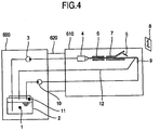
- Fig. 4 shows ink circulation path of the ink jet recording device according to the first embodiment of the present invention.
- an ink supply pump 3 As a path for supplying ink 1 to a nozzle 4, an ink supply pump 3, and as a path for recovering ink particles 5 collected from a gutter 9 into an ink container 2, an ink recovery pump 10, are included.
- the path having the ink supply pump 3 is connected to the nozzle 4 of the printing head 610 through the cable 620.
- an exhaust circulation path 12 which is connected to the gutter 9 of the printing head 610 through the cable 620, other than the path for supplying the ink 1 and the path for collecting the ink particles 5.
- the ink 1 is sent to the nozzle 4 by the ink supply pump 3, is made into the ink particles 5, and is jetted.
- the ink particles 5 used for printing are electrified inside an electrification electrode 6, are deflected by a deflection electrode 7 depending on amounts of electrifications of the ink particles 5, and reach a printing object 8.
- ink particles 5 not used for printing are not electrified inside the electrification electrode 6, they are not deflected in the deflection electrode 7 and fly to the gutter 9 to be collected there.
- the exhaust circulation path 12 connected from the ink container 2 to the gutter 9 discharges solvent vapor 11 filling inside the ink container 2 to the gutter 9.
- the gutter 9 recovers the ink particles 5, and simultaneously recovers the solvent vapor 11.
- the ink recovery pump 10 returns the ink particles 5 and the solvent vapor 11 to the ink container 2.
- the solvent vapor 11 Since being sent from the ink container 2 through the exhaust circulation path 12 to the gutter 9 and returned to the ink container 2 by the ink recovery pump 10, the solvent vapor 11 is always circulating.
- Fig. 1 shows a schematic view of a gutter according to the first embodiment of the present invention.
- the gutter 9 comprises two components of an ink flow path block 13 and an exhaust flow path block 14.
- the shape of the ink flow path block 13 is a circular pipe, and the ink particles 5 which are jetted from the nozzle 4 and not used for printing, fly to an ink inflow port 16 of the ink flow path block 13 and collide with an ink collision plane 17.
- the position of an exhaust connection port 15 of the ink flow path block 13 is provided between the ink inflow port 16 and the ink collision plane 17.
- the ink flow path block 13 has a shape of a circular pipe and is a bent product, and the part of the ink collision plane 17 is a curved plane, during collision of the ink particles 5, splashes do not occur.
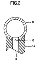
- Fig. 2 is a cross-sectional view, taken along line II-II in Fig. 1 , of the gutter.
- connection portion between the ink flow path block 14 and the exhaust flow path block 15 By causing the connection portion between the ink flow path block 14 and the exhaust flow path block 15 to have a shape so that a concave part and a convex part closely fit with each other, flowing out of the solvent vapor 11 and taking air in from external air from the connection portion are prevented.
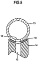
- FIG. 5 Another structure by which the similar effect can be obtained is shown in Fig. 5 .
- An elastic body 18 is intervened between the ink flow path block 14 and the exhaust flow path block 15.
- the shape of the elastic body 18 is a shape of doughnut having a space at its center portion.
- Fig. 7 is a view illustrating a prior art technology mode in which exhaust gas is supplied to a printing head 32.
- the ink jet recording device is separated into a main body 31 and a printing head 32, and between them are connected by a cable for protecting a piping tube and an electric wire.
- the ink in the ink container 33 in the main body 31 is sucked by the supply pump 34, and then fed to a secondary side.
- Foreign mattes in the pumped ink are removed by a filter 35, and then adjusted to a predetermined pressure by a pressure regulator 36. Wile the adjusted pressure being monitored by a pressure gauge 37, the ink is sent to the printing head 32.
- the ink is made ink particles 39 by jetted from a nozzle 38, and electrified by an electrification electrode 40 according to need and deflected by a deflection electrode part 41 to which a high voltage is applied, then used for printing.
- Ink particles 42 not used for printing is caught by a gutter 43, passed through a recovery path 44, removed foreign matters by a recovery filter 45, sucked by a recovery pump 46, and then returned to the ink container 33.
- the concentration of the ink held inside the ink container 33 is measured by a densitometer 47, periodically.
- a 3-port electromagnetic valve 49 is arranged on the exhaust circulation path 48.
- An inlet thereof is one port for the exhaust circulation path 48, an outlet thereof has two ports respectively connected to the exhaust circulation path 50 and a discharge outside device path 51, and ON/OFF of the 3-port electromagnetic valve 49 causes only one of the outlet ports to be in an open state.
- the exhaust circulation path 50 is connected to a port so as to be in a normal open state
- the discharge outside device path 51 is connected to a port so as to be in a normal closed state.
- the 3-port electromagnetic valve 49 when the 3-port electromagnetic valve 49 is in OFF (voltage is not applied) state, the exhaust gas is sent to the gutter 43 through the exhaust circulation path 50, and together with the collected ink sent into the ink container 33 through the recovery path 44.
- the 3-port electromagnetic valve 49 When the 3-port electromagnetic valve 49 is in ON (voltage is applied) state (operation state), the exhaust circulation path 50 becomes in a closed state, and the exhaust gas is sent into a solvent recovery device 52 through the discharge outside device path 51.
- a Peltier module is incorporated in the solvent recovery device 52, and by cooling the exhaust gas, the solvent component in the exhaust gas is liquefied and recovered.
- the exhaust gas in which the solvent component is separated is discharged outside the device from an exhaust port 54 through an exhaust path 53.
- the exhaust gas sent to the solvent recovery device 52 is sent to a solvent liquefier included inside the solvent recovery device.
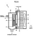
- a solvent liquefier one example thereof will be described with reference to Fig. 12 .
- the exhaust gas is cooled, volatilized solvent is liquefied, and the liquefied solvent is guided to a recovery container (not shown). Moreover, after being warmed in the solvent liquefier 61, the exhaust gas is adapted to be guided to the printing head 610.
- a cooling plate 63 is attached at a low temperature (heat absorption) side of the Peltier module 62.
- the cooling plate 63 is made of SUS 304, in which a thermo-couple 64 is included, which controls the temperature of the cooling plate 63 by the input current of the Peltier module 62.
- the cooling capacity of the Peltier module used in the present embodiment is 10 W.
- heat radiating fins 65 are attached at a high temperature (heat radiation) side of the Peltier module 62.
- a cooling fan 66 is attached to the heat radiating fins 65, and, while blowing ambient air on the heat radiating fins 65, cools the heat radiating fins 65.
- a heat insulation sheet 67 is placed so as to surround the Peltier module 62, and thermally insulates between the heat radiating fins 65 and the cooling plate 63.
- a case 68 covers the cooling plate 63, and a path to the ink container, a path to the nozzle head, and a passage 69 to the heat radiating fins 65 are connected.
- the exhaust gas from the ink container is guided into the case 68 from the discharge outside device path 51.
- the exhaust gas is cooled by the cooling plate 63 and then liquefied.
- the liquefied liquid adheres to the surface of the cooling plate 63 in membrane. And soon it gathers to a tip portion 70 at a lower side of the cooling plate 63 due to the weight thereof, becomes to droplets and falls, and is returned to a solvent recovery container through a recovery tube.
- the exhaust gas after contacted to the cooling plate 63 passes through a flow path 71 provided to the heat radiating fins 65 from the passage 69. At that time, the cooled exhaust gas is warmed to near ambient temperature by the flow path 71.
- the exhaust gas is supplied to the printing head 610, the temperature inside the printing head 610 is not reduced by the exhaust gas, thereby, dew condensation does not occur. Further, since the exhaust gas supplied inside the printing head is recovered into the ink container together with ink by the gutter, an amount of solvent released outside the ink jet recording device can be reduced.
- Fig. 9 shows an operational flow of the exhaust gas in the present embodiment.
- measurement of the ink concentration is performed at intervals of 30 minutes.
- the 3-port electromagnetic valve 49 is caused to be in ON state so that the exhaust gas is discharged outside the device.
- the operation is continued until the ink concentration becomes more than 100%.
- the 3-port electromagnetic valve 49 is caused to be in OFF state, and the exhaust gas is sent toward the gutter 43 of the printing head 32, thus exhaustion and circulation of the exhaust gas are performed.
- the operation is continued unless the ink concentration becomes less than 95%.
- the configuration of the third embodiment illustrated in Fig. 10 uses a manual type valve 55 instead of the 3-port electromagnetic valve 49 in the second embodiment.
- the manual type valve 55 by causing the exhaustion path 48 and the exhaust circulation path 50 to be in open state, the discharge outside device path 51 can be closed, and on the other hand, by causing the exhaustion path 48 and the exhaust circulation path 50 to be in closed state, the discharge outside device path 51 can be open state.
- This configuration enables an operator of the ink jet recording device to arbitrarily switch between the exhaust circulation and the discharge outside device.
- Fig. 11 shows the operational flow of the ink jet recording device according to the present embodiment is illustrated.
- the measurement of the ink concentration is performed at intervals of 30 minutes.
- an alarm is output from the ink jet recording device, and in a display screen, an indication to operate the manually-operated valve so as to switch the state thereof where the exhaust gas is discharged outside the device, is displayed.
- the display and the alarm are adapted to be deletable by the confirmation operation of the operator.
- an alarm is also output, and in the display screen, an indication to operate the manually-operated valve so as to switch the state thereof into the exhaust circulation state where the exhaust gas is sent toward the gutter 43 of the printing head 32, is displayed.
- the display and the alarm are adapted to be deletable by the confirmation operation of the operator.
- An ink supply flow path 100 comprises an ink container 81 to accumulate ink, an ink supply electromagnetic valve 82 to perform switching of the ink supply flow path to be open or closed, a supply pump 83 to pump the ink, a regulating valve 84 to adjust ink pressure, a pressure gauge 85 to display the pressure of the supplied ink, and a filter 86.
- the ink is supplied from the ink container 81, through the ink supply electromagnetic valve 82, the supply pump 83, and the regulating valve 84, and, via the printing head cable 620, to the printing head 610.
- the ink supplied inside the printing head 610 is supplied to a first nozzle 110a, and jetted.
- An excitation source (not illustrated in the drawing) is connected to the first nozzle 110a, and by applying an excitation voltage to the first nozzle 110a, vibration is generated there depending on the frequency thereof.
- the ink jetted from the first nozzle 110a is made as ink particles 111 continuously and regularly by the above-mentioned vibration.
- a recording signal source (not shown) is connected to a first electrification electrode 112a, and by applying a recording signal voltage on the first electrification electrode 112a, the ink particles 111 are individually electrified to a desired charge amount.
- a first upper deflection electrode 113a becomes in a high voltage state, and a static electric field is formed between the first upper deflection electrode 113a and a first lower deflection electrode 114a grounded.
- the electrified ink particles 111 fly and adhere to a recording medium. In this manner, by adhering each of the ink particles 111 to a desired position, characters and letters are formed.
- ink particles which do not involved in recording are collected by the first gutter 115a arranged inside the printing head 610, sucked by the recovery pump 90 arranged in the main body 600, and by being passed through an ink recovery path 116 including a filter 92, and an ink recovery electromagnetic valve 91, returned to the ink container 81, and reused.
- the ink jetted from the second nozzle 110b similar to the ink jetted from the first nozzle 110a, is also made into ink particles 111 by excitation, which are electrified by a second electrification electrode 112b, deflected between a second upper deflection electrode 113b and a second lower deflection electrode 114b, and perform desired flight.
- ink particles 111 which do not involved in recording are collected by the first gutter 115a, are collected by a second gutter 115b, and by being passed through the ink recovery path 116, returned to the ink container 81.
- a solvent vapor supply flow path 120 is connected to the ink container 81 at a portion upper than the liquid level of the ink, and connected from the main body 600 via the printing head cable 620 to the printing head 610.
- the solvent vapor supply flow path 120 is branched into two flow paths near the gutters inside the printing head 610, and one of them is communicated with the first gutter 115a and the other of them is communicated with the second gutter 115b.
- Gas taken in simultaneously during recovering ink collected by the gutters, is passed through the recovery path 116 into the ink container 81. At that time, a part of the solvent component of the ink is volatilized in gas into a solvent vapor.
- the gas containing the vapor of excess solvent in the ink container is fed to the first and second gutters 115a and 115b via the solvent vapor supply flow path 120, again taken in simultaneously at the first and second gutters 115a and 115b when they recover the ink, and returned into the ink container 81.
- the solvent vapor is circulated inside the solvent vapor supply flow path 120 and the recovery path 116. Since, the circulated solvent vapor will be soon in a saturated state and new solvent component will not be volatilized, it is possible for the ink jet recording device to reduce the solvent amount used. At that time, if the balance between the recovery amount and the supply amount of the circulated gas is collapsed, the solvent vapor will be discharged from a first ink collection port 117a of the first gutter 115a or a second ink collection port 117b of the second gutter 115b, or inversely, new gas will be taken in. In this situation, the amount of solvent volatilization cannot be reduced.
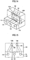
- the solvent vapor supply flow path 120 is arranged at the center between the first and second gutters 115a and 115b, that is, the distance between the center and the first gutter 115a is equal to the distance between the center and the second gutter 115b, and the flow paths after the branch 121 are configured so that the length to the first gutter 115a and the length to the second gutter 115b are the same one, and the diameters thereof are the same one.
- Figs. 14 and 15 show schematic views thereof. The flow paths are caused to have the same shape and the same size, so that the resistance of fluid thereof can be the same, resulting in maintenance of the balance.
- a member constituting the first gutter 115a, the second gutter 115b, the solvent vapor supply flow path 120, and a solvent vapor inlet port 122 comprises a gutter base member 130 and a gutter base member 131, and the flow path of the branch 121 of the solvent vapor supply flow path 120 is divided so that the flow path of the branch 121 is constituted between the gutter base member 130 and the gutter base member 131.
- the air tightness between the gutter base member 130 and the gutter base member 131 should be ensured by welding and adhesion, or intervening an elastic sealing material between them.
Landscapes
- Ink Jet (AREA)
- Particle Formation And Scattering Control In Inkjet Printers (AREA)
Claims (4)
- Tintenstrahlaufzeichnungsvorrichtung mit
einem Hauptkörper (600) ausgerüstet mit einem Tintenbehälter (2) zum Ansammeln von Tinte (1), einer Tintenzuführpumpe (3) zum Zuführen der Tinte, einer Tintenrückgewinnungspumpe (10) zum Rückgewinnen der Tinte (1) und einer Steuereinheit,
einem Druckkopf (610) ausgerüstet mit einer Düse (4) zum Ausstoßen der von dem Hauptkörper (600) zugeführten Tinte (1) als Tintenpartikel (5), einer Elektrifizierungselektrode (6) zum Elektrifizieren der Tintenpartikel (5), einer Ablenkelektrode (7) zum Ablenken der elektrifizierten Tintenpartikel (5) und einer Abflussrinne (9) zum Sammeln von Tintenpartikeln (5), die nicht zum Drucken verwendet wurden, und
einem Kabel (620), in dem ein Tintenzuführströmungspfad zum Zuführen der Tinte aus dem Hauptkörper (600) zu dem Druckkopf (610), ein Tintenrückgewinnungsströmungspfad zum Rückführen der durch die Abflussrinne (9) gesammelten Tintenpartikel in den Tintenbehälter (1), einen Ausstoßzirkulationspfad (12), der den Tintenbehälter (2) und die Abflussrinne verbindet, und verschiedene Signalleitungen zum Anschließen der Steuereinheit und des Druckkopfs (610) angeordnet sind,
wobei:die Abflussrinne (9) einen Tintenströmungspfadblock (13), in dem Tinte strömt, und einen Auslassströmungspfadblock (14) aufweist;eine Tinteneinströmungsöffnung (16) zum Empfangen von von der Düse (4) ausgestoßener Tinte und eine Tintenkollisionsebene (17), mit der empfangene Tinte kollidiert, in dem Tintenströmungspfadblock (13) gebildet sind;in dem Ausstoßströmungspfadblock Ausstoßlösungsmitteldampf (11) aus dem Tintenbehälter (2) zu der Abflussrinne (9) strömt;eine Ausstoßverbindungsöffnung (15) zum Anschluss an den Ausstoßströmungspfadblock (14) zwischen der Tinteneinströmungsöffnung (16) und der Tintenkollisionsebene (17) vorgesehen ist;die Abflussrinne (9) zwei Elemente des Tintenströmungspfadblocks (13) und des Ausstoßströmungspfadblocks aufweist; undder Tintenströmungspfadblock (13) ein biegegeformtes Produkt eines kreisförmigen Rohrs ist, und die Tintenkollisionsebene (17) als ein gekrümmter Abschnitt konfiguriert ist, die in der Richtung der Tintenströmung gekrümmt ist. - Tintenstrahlaufzeichnungsvorrichtung nach Anspruch 1, wobei ein Verbindungsabschnitt des Tintenströmungspfadblocks (13) und des Ausstoßströmungspfadblocks (14) in einer derartigen Form gebildet ist, dass ein konkaver Teil und ein konvexer Teil ineinander passen.
- Tintenstrahlaufzeichnungsvorrichtung nach Anspruch 1, wobei ein elastischer Körper (18) als ein Dichtelement in einen Verbindungsabschnitt des Tintenströmungspfadblocks (13) und des Ausstoßströmungspfadblocks (14) zwischengeschoben ist.
- Tintenstrahlaufzeichnungsvorrichtung nach Anspruch 1, wobei ein Verbindungsabschnitt des Tintenströmungspfadblocks (13) und des Ausstoßströmungspfadblocks (14) durch Kleben, Schweißen oder dergleichen eng verbunden ist.
Priority Applications (1)
| Application Number | Priority Date | Filing Date | Title |
|---|---|---|---|
| EP10007317A EP2241442B1 (de) | 2008-01-28 | 2008-02-28 | Tintenstrahlaufzeichnungsvorrichtung |
Applications Claiming Priority (1)
| Application Number | Priority Date | Filing Date | Title |
|---|---|---|---|
| JP2008015748 | 2008-01-28 |
Related Child Applications (2)
| Application Number | Title | Priority Date | Filing Date |
|---|---|---|---|
| EP10007317A Division-Into EP2241442B1 (de) | 2008-01-28 | 2008-02-28 | Tintenstrahlaufzeichnungsvorrichtung |
| EP10007317.0 Division-Into | 2010-07-15 |
Publications (4)
| Publication Number | Publication Date |
|---|---|
| EP2082879A2 EP2082879A2 (de) | 2009-07-29 |
| EP2082879A3 EP2082879A3 (de) | 2010-10-27 |
| EP2082879B1 EP2082879B1 (de) | 2013-08-14 |
| EP2082879B2 true EP2082879B2 (de) | 2020-02-12 |
Family
ID=40377435
Family Applications (2)
| Application Number | Title | Priority Date | Filing Date |
|---|---|---|---|
| EP08250679.1A Active EP2082879B2 (de) | 2008-01-28 | 2008-02-28 | Tintenstrahlaufzeichnungsvorrichtung |
| EP10007317A Active EP2241442B1 (de) | 2008-01-28 | 2008-02-28 | Tintenstrahlaufzeichnungsvorrichtung |
Family Applications After (1)
| Application Number | Title | Priority Date | Filing Date |
|---|---|---|---|
| EP10007317A Active EP2241442B1 (de) | 2008-01-28 | 2008-02-28 | Tintenstrahlaufzeichnungsvorrichtung |
Country Status (5)
| Country | Link |
|---|---|
| US (3) | US8308282B2 (de) |
| EP (2) | EP2082879B2 (de) |
| JP (1) | JP5260336B2 (de) |
| CN (1) | CN101497264B (de) |
| AT (1) | ATE530342T1 (de) |
Families Citing this family (19)
| Publication number | Priority date | Publication date | Assignee | Title |
|---|---|---|---|---|
| GB2447919B (en) | 2007-03-27 | 2012-04-04 | Linx Printing Tech | Ink jet printing |
| USD610607S1 (en) * | 2008-05-23 | 2010-02-23 | Fujifilm Corporation | Inkjet recording device |
| WO2010150437A1 (ja) * | 2009-06-25 | 2010-12-29 | 株式会社日立産機システム | インクジェット記録装置 |
| JP2012045749A (ja) * | 2010-08-25 | 2012-03-08 | Hitachi Industrial Equipment Systems Co Ltd | インクジェット記録装置 |
| JP2012066423A (ja) * | 2010-09-22 | 2012-04-05 | Hitachi Industrial Equipment Systems Co Ltd | インクジェット記録装置 |
| JP5743832B2 (ja) * | 2011-09-30 | 2015-07-01 | 株式会社日立産機システム | インクジェット記録装置 |
| JP5775423B2 (ja) * | 2011-11-04 | 2015-09-09 | 株式会社日立産機システム | インクジェット記録装置及びその記録処理方法 |
| JP2013215929A (ja) * | 2012-04-05 | 2013-10-24 | Hitachi Industrial Equipment Systems Co Ltd | インクジェット記録装置 |
| US9044954B1 (en) | 2012-05-14 | 2015-06-02 | Videojet Technologies Inc. | Ink jet printer |
| US9227421B2 (en) | 2012-05-14 | 2016-01-05 | Videojet Technoogies Inc. | Ink jet printer |
| US8840230B2 (en) * | 2012-06-04 | 2014-09-23 | Xerox Corporation | Ink waste tray configured with one way filter |
| JP5997538B2 (ja) * | 2012-08-07 | 2016-09-28 | 株式会社日立産機システム | インクジェット記録装置 |
| CN103448366B (zh) * | 2013-06-27 | 2016-12-28 | 北京大学深圳研究生院 | 一种喷墨打印系统及其应用 |
| JP6338861B2 (ja) * | 2014-01-08 | 2018-06-06 | 株式会社日立産機システム | インクジェット記録装置 |
| EP3152061B1 (de) | 2014-06-05 | 2020-10-07 | Videojet Technologies Inc. | Kontinuierlicher tintenstrahldruckkopf eingebetteter einstellungsfreier ladeelektrode |
| CN105818369B (zh) * | 2015-01-05 | 2019-06-14 | 三纬国际立体列印科技股份有限公司 | 立体打印机喷头 |
| JP6707261B2 (ja) * | 2015-03-20 | 2020-06-10 | セイコーエプソン株式会社 | 印刷装置 |
| JP6395961B1 (ja) * | 2018-01-29 | 2018-09-26 | 紀州技研工業株式会社 | インクジェットプリンタ |
| JP7326051B2 (ja) * | 2019-07-10 | 2023-08-15 | 株式会社日立産機システム | インクジェット記録装置およびインクジェット記録装置の制御方法 |
Citations (4)
| Publication number | Priority date | Publication date | Assignee | Title |
|---|---|---|---|---|
| JPS6011364A (ja) † | 1983-07-01 | 1985-01-21 | Hitachi Ltd | インクジエツト記録装置 |
| US4575735A (en) † | 1983-02-04 | 1986-03-11 | Willett International Limited | Droplet depositing viscosity line-pressure sensing control for fluid re-supply |
| US20020130931A1 (en) † | 2001-03-13 | 2002-09-19 | Eastman Kodak Company | Continuous ink-jet printing method and apparatus for correcting ink drop placement |
| WO2008117013A1 (en) † | 2007-03-27 | 2008-10-02 | Linx Printing Technologies Ltd | Ink jet printing |
Family Cites Families (61)
| Publication number | Priority date | Publication date | Assignee | Title |
|---|---|---|---|---|
| DE2447919C3 (de) | 1974-10-08 | 1978-10-26 | Haug & Co Kg, 7023 Echterdingen | Vorrichtung zur Erzeugung eines mit positiven und negativen Ionen angereicherten Gasstromes zur Beseitigung statischer Ladungen |
| JPS5835152B2 (ja) * | 1975-09-18 | 1983-08-01 | ソニー株式会社 | インクジエツトシヨガソウチ |
| US4121222A (en) * | 1977-09-06 | 1978-10-17 | A. B. Dick Company | Drop counter ink replenishing system |
| JPS555874A (en) | 1978-06-29 | 1980-01-17 | Sharp Corp | Ink collecting device in jet printer |
| JPS5670962A (en) * | 1979-11-16 | 1981-06-13 | Ricoh Co Ltd | Controlling method for ink density |
| US4283730A (en) * | 1979-12-06 | 1981-08-11 | Graf Ronald E | Droplet control aspects--ink evaporation reduction; low voltage contact angle control device; droplet trajectory release modes; uses for metallic ink drops in circuit wiring and press printing |
| US4286274A (en) * | 1980-03-06 | 1981-08-25 | Burroughs Corporation | Ink droplet catcher assembly |
| JPS56150584A (en) * | 1980-04-24 | 1981-11-21 | Ricoh Co Ltd | Control of ink density |
| US4360817A (en) * | 1981-05-15 | 1982-11-23 | A. B. Dick Company | Low evaporation ink catcher for ink jet printing system |
| US4413267A (en) * | 1981-12-18 | 1983-11-01 | Centronics Data Computer Corp. | Ink supply system for ink jet printing apparatus |
| JPS5981177A (ja) * | 1982-06-17 | 1984-05-10 | Ricoh Co Ltd | インクジエツト印写装置におけるインク粘度制御装置 |
| US4460904A (en) | 1982-11-05 | 1984-07-17 | Xerox Corporation | Ink jet ink handling system |
| US4602662A (en) * | 1983-10-11 | 1986-07-29 | Videojet Systems International, Inc. | Valve for liquid marking systems |
| GB8328000D0 (en) * | 1983-10-19 | 1983-11-23 | Domino Printing Sciences Ltd | Hydraulic systems |
| US5202702A (en) * | 1985-04-08 | 1993-04-13 | Canon Kabushiki Kaisha | Ink jet recording apparatus and a method of cleaning a recording head used in the apparatus |
| GB8530885D0 (en) * | 1985-12-16 | 1986-01-29 | Domino Printing Sciences Plc | Ink jet printing system |
| JPS63122545A (ja) | 1986-11-12 | 1988-05-26 | Yokogawa Electric Corp | インクジエツトプリンタ |
| JPS63130349A (ja) * | 1986-11-20 | 1988-06-02 | Ricoh Co Ltd | インクジエツト印字装置のヘツド部分構造 |
| JPH01247167A (ja) * | 1988-03-30 | 1989-10-03 | Hitachi Ltd | インクジェット記録装置のインク回収装置 |
| GB8810241D0 (en) * | 1988-04-29 | 1988-06-02 | Am Int | Drop-on-demand printhead |
| US5252993A (en) * | 1988-09-07 | 1993-10-12 | Seiko Epson Corporation | Capping apparatus for an ink jet printer |
| SG47854A1 (en) * | 1988-09-07 | 1998-04-17 | Seiko Epson Corp | Ink jet printer sealing method and apparatus |
| US4890119A (en) | 1989-01-12 | 1989-12-26 | A. B. Dick Company | Variable orientation ink catcher |
| FR2652540B1 (fr) * | 1989-10-02 | 1995-06-02 | Imaje Sa | Circuit d'encre notamment destine a la mise en pression d'une encre a pigments pour imprimante a jet d'encre. |
| US5155528A (en) * | 1990-07-06 | 1992-10-13 | Nippon Steel Corporation | Apparatus for controlling concentration of toner in the liquid toner of a recording apparatus |
| US5418557A (en) * | 1991-10-03 | 1995-05-23 | Videojet Systems International, Inc. | Drop quality control system for jet printing |
| JPH05162328A (ja) * | 1991-12-11 | 1993-06-29 | Canon Inc | インクジェット記録装置 |
| GB9205342D0 (en) * | 1992-03-12 | 1992-04-22 | Willett Int Ltd | System |
| JP2725515B2 (ja) | 1992-03-12 | 1998-03-11 | 株式会社日立製作所 | インクジェット記録装置 |
| GB9205330D0 (en) * | 1992-03-12 | 1992-04-22 | Willett Int Ltd | Recovery system |
| FR2690648B1 (fr) * | 1992-04-30 | 1994-07-08 | Imaje | Methode d'optimisation du fonctionnement d'une imprimante a jet d'encre et imprimante utilisant une telle methode. |
| US5532720A (en) * | 1993-09-15 | 1996-07-02 | Quad/Tech, Inc. | Solvent recovery system for ink jet printer |
| US5623292A (en) * | 1993-12-17 | 1997-04-22 | Videojet Systems International, Inc. | Temperature controller for ink jet printing |
| FR2714710B1 (fr) * | 1993-12-30 | 1996-03-15 | Gaz De France | Appareillage de mise en place d'une prise de branchement sur une canalisation. |
| JP3190211B2 (ja) | 1994-01-25 | 2001-07-23 | キヤノン株式会社 | 異なるインクジェット記録ヘッドを選択的に搭載可能なインクジェット記録装置及びそのヘッド回復方法 |
| JP3324629B2 (ja) * | 1995-03-13 | 2002-09-17 | セイコーエプソン株式会社 | インクジェット式印刷ユニットの保管ケース |
| US5758580A (en) * | 1996-03-13 | 1998-06-02 | Heidelberger Druckmaschinen Ag | Printing unit using various ink types |
| JPH10202898A (ja) | 1997-01-27 | 1998-08-04 | Hitachi Ltd | インクジェット記録装置及びその循環装置の製造方法 |
| JPH10324000A (ja) * | 1997-05-27 | 1998-12-08 | Hitachi Ltd | インクジェット記録装置のノズル洗浄装置 |
| US6248168B1 (en) * | 1997-12-15 | 2001-06-19 | Tokyo Electron Limited | Spin coating apparatus including aging unit and solvent replacement unit |
| GB9819081D0 (en) * | 1998-09-03 | 1998-10-28 | Videojet Systems Int | An ink jet printing system |
| JP2000094657A (ja) * | 1998-09-25 | 2000-04-04 | Hitachi Ltd | インクジェット記録装置 |
| US6398351B1 (en) * | 1998-12-14 | 2002-06-04 | Scitex Digital Printing, Inc. | Flush system for ink change |
| US6234620B1 (en) | 1999-06-29 | 2001-05-22 | Eastman Kodak Company | Continuous ink jet printer catcher and method for making same |
| US6588339B2 (en) * | 2000-06-19 | 2003-07-08 | Fuji Photo Film Co., Ltd. | Plate-making method, plate-making apparatus, computer-to-cylinder type lithographic printing process and computer-to-cylinder type lithographic printing apparatus |
| US20030016264A1 (en) * | 2001-07-16 | 2003-01-23 | Eastman Kodak Company | Continuous ink-jet printing apparatus with integral cleaning |
| US6588889B2 (en) * | 2001-07-16 | 2003-07-08 | Eastman Kodak Company | Continuous ink-jet printing apparatus with pre-conditioned air flow |
| US6883904B2 (en) * | 2002-04-24 | 2005-04-26 | Eastman Kodak Company | Apparatus and method for maintaining constant drop volumes in a continuous stream ink jet printer |
| US6802588B2 (en) * | 2002-08-26 | 2004-10-12 | Eastman Kodak Company | Fluid jet apparatus and method for cleaning inkjet printheads |
| US6575566B1 (en) * | 2002-09-18 | 2003-06-10 | Eastman Kodak Company | Continuous inkjet printhead with selectable printing volumes of ink |
| US6869160B2 (en) * | 2002-10-04 | 2005-03-22 | Eastman Kodak Company | Purge shutdown for a solvent ink printing system |
| US6666548B1 (en) * | 2002-11-04 | 2003-12-23 | Eastman Kodak Company | Method and apparatus for continuous marking |
| JP2004322558A (ja) | 2003-04-28 | 2004-11-18 | Hitachi Ltd | インクジェット記録装置 |
| JP4354786B2 (ja) * | 2003-11-28 | 2009-10-28 | 富士フイルム株式会社 | インク濃度検出方法およびインクジェット記録装置 |
| JP4383996B2 (ja) * | 2004-09-29 | 2009-12-16 | 株式会社東芝 | 屈折率変化装置および屈折率変化方法 |
| JP3987519B2 (ja) * | 2004-09-30 | 2007-10-10 | 株式会社東芝 | 屈折率変化装置及び屈折率変化方法 |
| FR2879961B1 (fr) * | 2004-12-23 | 2016-08-19 | Imaje Sa | Nettoyage d'une tete d'impression |
| JP4846241B2 (ja) * | 2005-01-21 | 2011-12-28 | 株式会社東芝 | 光屈折率変化素子 |
| US7475974B2 (en) * | 2005-03-11 | 2009-01-13 | Hitachi Industrial Equipment Co., Ltd. | Inkjet recording apparatus |
| US7806073B2 (en) * | 2005-03-22 | 2010-10-05 | Cytonix Llc | System and method for coating articles |
| JP4372048B2 (ja) * | 2005-05-30 | 2009-11-25 | 株式会社東芝 | 屈折率変化素子 |
-
2008
- 2008-02-28 AT AT10007317T patent/ATE530342T1/de not_active IP Right Cessation
- 2008-02-28 EP EP08250679.1A patent/EP2082879B2/de active Active
- 2008-02-28 EP EP10007317A patent/EP2241442B1/de active Active
- 2008-02-28 US US12/074,171 patent/US8308282B2/en active Active
- 2008-02-29 CN CN2008100823535A patent/CN101497264B/zh active Active
-
2009
- 2009-01-27 JP JP2009014887A patent/JP5260336B2/ja active Active
- 2009-10-09 US US12/576,916 patent/US8337004B2/en active Active
- 2009-10-09 US US12/576,907 patent/US8333463B2/en active Active
Patent Citations (4)
| Publication number | Priority date | Publication date | Assignee | Title |
|---|---|---|---|---|
| US4575735A (en) † | 1983-02-04 | 1986-03-11 | Willett International Limited | Droplet depositing viscosity line-pressure sensing control for fluid re-supply |
| JPS6011364A (ja) † | 1983-07-01 | 1985-01-21 | Hitachi Ltd | インクジエツト記録装置 |
| US20020130931A1 (en) † | 2001-03-13 | 2002-09-19 | Eastman Kodak Company | Continuous ink-jet printing method and apparatus for correcting ink drop placement |
| WO2008117013A1 (en) † | 2007-03-27 | 2008-10-02 | Linx Printing Technologies Ltd | Ink jet printing |
Also Published As
| Publication number | Publication date |
|---|---|
| CN101497264B (zh) | 2013-11-13 |
| EP2241442A2 (de) | 2010-10-20 |
| JP5260336B2 (ja) | 2013-08-14 |
| EP2241442B1 (de) | 2011-10-26 |
| US20090189964A1 (en) | 2009-07-30 |
| US8337004B2 (en) | 2012-12-25 |
| ATE530342T1 (de) | 2011-11-15 |
| US8308282B2 (en) | 2012-11-13 |
| US20100026754A1 (en) | 2010-02-04 |
| EP2082879A3 (de) | 2010-10-27 |
| US20100026770A1 (en) | 2010-02-04 |
| US8333463B2 (en) | 2012-12-18 |
| EP2082879A2 (de) | 2009-07-29 |
| EP2082879B1 (de) | 2013-08-14 |
| CN101497264A (zh) | 2009-08-05 |
| JP2009202583A (ja) | 2009-09-10 |
| EP2241442A3 (de) | 2010-10-27 |
Similar Documents
| Publication | Publication Date | Title |
|---|---|---|
| EP2082879B1 (de) | Tintenstrahlaufzeichnungsvorrichtung | |
| EP3152061B1 (de) | Kontinuierlicher tintenstrahldruckkopf eingebetteter einstellungsfreier ladeelektrode | |
| CA1056899A (en) | Vacuum return system for ink jet printing apparatus | |
| JP5997538B2 (ja) | インクジェット記録装置 | |
| CN106079895B (zh) | 气液分离器和具备该气液分离器的喷墨记录装置 | |
| JP5940005B2 (ja) | インクジェット記録装置 | |
| CN100427315C (zh) | 喷墨式记录装置 | |
| US20160361926A1 (en) | Inkjet Recording Device | |
| WO2012111039A1 (ja) | インクジェット記録装置 | |
| JP4832356B2 (ja) | インクジェット記録装置 | |
| JP6401815B2 (ja) | 気液分離器、及びそれを備えたインクジェット記録装置 | |
| JP4579727B2 (ja) | インクジェット記録装置 | |
| EP0378323B1 (de) | Tintenauffänger mit variabler Ausrichtung | |
| EP0805039B1 (de) | Tintenauffangvorrichtung mit geringem Luftstrom für kontinuierlich arbeitenden Tintenstrahldrucker | |
| JP6130560B2 (ja) | 気液分離器、及びそれを備えたインクジェット記録装置 | |
| JPS58212952A (ja) | インクジエツト印写装置 |
Legal Events
| Date | Code | Title | Description |
|---|---|---|---|
| PUAI | Public reference made under article 153(3) epc to a published international application that has entered the european phase |
Free format text: ORIGINAL CODE: 0009012 |
|
| 17P | Request for examination filed |
Effective date: 20080314 |
|
| AK | Designated contracting states |
Kind code of ref document: A2 Designated state(s): AT BE BG CH CY CZ DE DK EE ES FI FR GB GR HR HU IE IS IT LI LT LU LV MC MT NL NO PL PT RO SE SI SK TR |
|
| AX | Request for extension of the european patent |
Extension state: AL BA MK RS |
|
| PUAL | Search report despatched |
Free format text: ORIGINAL CODE: 0009013 |
|
| AK | Designated contracting states |
Kind code of ref document: A3 Designated state(s): AT BE BG CH CY CZ DE DK EE ES FI FR GB GR HR HU IE IS IT LI LT LU LV MC MT NL NO PL PT RO SE SI SK TR |
|
| AX | Request for extension of the european patent |
Extension state: AL BA MK RS |
|
| 17Q | First examination report despatched |
Effective date: 20110329 |
|
| TPAC | Observations filed by third parties |
Free format text: ORIGINAL CODE: EPIDOSNTIPA |
|
| AKX | Designation fees paid |
Designated state(s): DE FR GB |
|
| GRAP | Despatch of communication of intention to grant a patent |
Free format text: ORIGINAL CODE: EPIDOSNIGR1 |
|
| GRAS | Grant fee paid |
Free format text: ORIGINAL CODE: EPIDOSNIGR3 |
|
| GRAA | (expected) grant |
Free format text: ORIGINAL CODE: 0009210 |
|
| AK | Designated contracting states |
Kind code of ref document: B1 Designated state(s): DE FR GB |
|
| REG | Reference to a national code |
Ref country code: GB Ref legal event code: FG4D |
|
| REG | Reference to a national code |
Ref country code: DE Ref legal event code: R096 Ref document number: 602008026723 Country of ref document: DE Effective date: 20131010 |
|
| PLBI | Opposition filed |
Free format text: ORIGINAL CODE: 0009260 |
|
| PLAX | Notice of opposition and request to file observation + time limit sent |
Free format text: ORIGINAL CODE: EPIDOSNOBS2 |
|
| 26 | Opposition filed |
Opponent name: VIDEOJET TECHNOLOGIES INC. Effective date: 20140514 |
|
| REG | Reference to a national code |
Ref country code: DE Ref legal event code: R026 Ref document number: 602008026723 Country of ref document: DE Effective date: 20140514 |
|
| PLBB | Reply of patent proprietor to notice(s) of opposition received |
Free format text: ORIGINAL CODE: EPIDOSNOBS3 |
|
| APBM | Appeal reference recorded |
Free format text: ORIGINAL CODE: EPIDOSNREFNO |
|
| APBP | Date of receipt of notice of appeal recorded |
Free format text: ORIGINAL CODE: EPIDOSNNOA2O |
|
| APAH | Appeal reference modified |
Free format text: ORIGINAL CODE: EPIDOSCREFNO |
|
| REG | Reference to a national code |
Ref country code: FR Ref legal event code: PLFP Year of fee payment: 9 |
|
| APBQ | Date of receipt of statement of grounds of appeal recorded |
Free format text: ORIGINAL CODE: EPIDOSNNOA3O |
|
| REG | Reference to a national code |
Ref country code: FR Ref legal event code: PLFP Year of fee payment: 10 |
|
| REG | Reference to a national code |
Ref country code: FR Ref legal event code: PLFP Year of fee payment: 11 |
|
| APBU | Appeal procedure closed |
Free format text: ORIGINAL CODE: EPIDOSNNOA9O |
|
| REG | Reference to a national code |
Ref country code: DE Ref legal event code: R082 Ref document number: 602008026723 Country of ref document: DE Representative=s name: MEWBURN ELLIS LLP, DE |
|
| PUAH | Patent maintained in amended form |
Free format text: ORIGINAL CODE: 0009272 |
|
| STAA | Information on the status of an ep patent application or granted ep patent |
Free format text: STATUS: PATENT MAINTAINED AS AMENDED |
|
| 27A | Patent maintained in amended form |
Effective date: 20200212 |
|
| AK | Designated contracting states |
Kind code of ref document: B2 Designated state(s): DE FR GB |
|
| REG | Reference to a national code |
Ref country code: DE Ref legal event code: R102 Ref document number: 602008026723 Country of ref document: DE |
|
| PGFP | Annual fee paid to national office [announced via postgrant information from national office to epo] |
Ref country code: GB Payment date: 20260122 Year of fee payment: 19 |
|
| PGFP | Annual fee paid to national office [announced via postgrant information from national office to epo] |
Ref country code: DE Payment date: 20260121 Year of fee payment: 19 |
|
| PGFP | Annual fee paid to national office [announced via postgrant information from national office to epo] |
Ref country code: FR Payment date: 20260121 Year of fee payment: 19 |