EP2083571A1 - Dynamisches bildkodierungsverfahren, dekodierungsverfahren, einrichtung dafür, programm dafür und das programm enthaltendes speichermedium - Google Patents
Dynamisches bildkodierungsverfahren, dekodierungsverfahren, einrichtung dafür, programm dafür und das programm enthaltendes speichermedium Download PDFInfo
- Publication number
- EP2083571A1 EP2083571A1 EP07830445A EP07830445A EP2083571A1 EP 2083571 A1 EP2083571 A1 EP 2083571A1 EP 07830445 A EP07830445 A EP 07830445A EP 07830445 A EP07830445 A EP 07830445A EP 2083571 A1 EP2083571 A1 EP 2083571A1
- Authority
- EP
- European Patent Office
- Prior art keywords
- frame
- area
- information
- encoding
- reference vector
- Prior art date
- Legal status (The legal status is an assumption and is not a legal conclusion. Google has not performed a legal analysis and makes no representation as to the accuracy of the status listed.)
- Ceased
Links
Images




Classifications
-
- H—ELECTRICITY
- H04—ELECTRIC COMMUNICATION TECHNIQUE
- H04N—PICTORIAL COMMUNICATION, e.g. TELEVISION
- H04N19/00—Methods or arrangements for coding, decoding, compressing or decompressing digital video signals
- H04N19/50—Methods or arrangements for coding, decoding, compressing or decompressing digital video signals using predictive coding
- H04N19/503—Methods or arrangements for coding, decoding, compressing or decompressing digital video signals using predictive coding involving temporal prediction
- H04N19/51—Motion estimation or motion compensation
- H04N19/577—Motion compensation with bidirectional frame interpolation, i.e. using B-pictures
-
- H—ELECTRICITY
- H04—ELECTRIC COMMUNICATION TECHNIQUE
- H04N—PICTORIAL COMMUNICATION, e.g. TELEVISION
- H04N19/00—Methods or arrangements for coding, decoding, compressing or decompressing digital video signals
- H04N19/10—Methods or arrangements for coding, decoding, compressing or decompressing digital video signals using adaptive coding
- H04N19/102—Methods or arrangements for coding, decoding, compressing or decompressing digital video signals using adaptive coding characterised by the element, parameter or selection affected or controlled by the adaptive coding
- H04N19/103—Selection of coding mode or of prediction mode
- H04N19/105—Selection of the reference unit for prediction within a chosen coding or prediction mode, e.g. adaptive choice of position and number of pixels used for prediction
-
- H—ELECTRICITY
- H04—ELECTRIC COMMUNICATION TECHNIQUE
- H04N—PICTORIAL COMMUNICATION, e.g. TELEVISION
- H04N19/00—Methods or arrangements for coding, decoding, compressing or decompressing digital video signals
- H04N19/50—Methods or arrangements for coding, decoding, compressing or decompressing digital video signals using predictive coding
- H04N19/503—Methods or arrangements for coding, decoding, compressing or decompressing digital video signals using predictive coding involving temporal prediction
- H04N19/51—Motion estimation or motion compensation
-
- H—ELECTRICITY
- H04—ELECTRIC COMMUNICATION TECHNIQUE
- H04N—PICTORIAL COMMUNICATION, e.g. TELEVISION
- H04N19/00—Methods or arrangements for coding, decoding, compressing or decompressing digital video signals
- H04N19/50—Methods or arrangements for coding, decoding, compressing or decompressing digital video signals using predictive coding
- H04N19/503—Methods or arrangements for coding, decoding, compressing or decompressing digital video signals using predictive coding involving temporal prediction
- H04N19/51—Motion estimation or motion compensation
- H04N19/513—Processing of motion vectors
- H04N19/517—Processing of motion vectors by encoding
- H04N19/52—Processing of motion vectors by encoding by predictive encoding
-
- H—ELECTRICITY
- H04—ELECTRIC COMMUNICATION TECHNIQUE
- H04N—PICTORIAL COMMUNICATION, e.g. TELEVISION
- H04N19/00—Methods or arrangements for coding, decoding, compressing or decompressing digital video signals
- H04N19/50—Methods or arrangements for coding, decoding, compressing or decompressing digital video signals using predictive coding
- H04N19/597—Methods or arrangements for coding, decoding, compressing or decompressing digital video signals using predictive coding specially adapted for multi-view video sequence encoding
-
- H—ELECTRICITY
- H04—ELECTRIC COMMUNICATION TECHNIQUE
- H04N—PICTORIAL COMMUNICATION, e.g. TELEVISION
- H04N19/00—Methods or arrangements for coding, decoding, compressing or decompressing digital video signals
- H04N19/60—Methods or arrangements for coding, decoding, compressing or decompressing digital video signals using transform coding
- H04N19/61—Methods or arrangements for coding, decoding, compressing or decompressing digital video signals using transform coding in combination with predictive coding
-
- H—ELECTRICITY
- H04—ELECTRIC COMMUNICATION TECHNIQUE
- H04N—PICTORIAL COMMUNICATION, e.g. TELEVISION
- H04N19/00—Methods or arrangements for coding, decoding, compressing or decompressing digital video signals
- H04N19/70—Methods or arrangements for coding, decoding, compressing or decompressing digital video signals characterised by syntax aspects related to video coding, e.g. related to compression standards
Definitions
- the present invention relates to a video encoding method for encoding a video image using an interframe predictive encoding method and a corresponding apparatus; a video decoding method for decoding encoded data generated by the video encoding method and a corresponding apparatus; a video encoding program for implementing the video encoding method and a computer-readable storage medium which stores the program; and a video decoding program for implementing the video decoding method and a computer-readable storage medium which stores the program.
- Priority is claimed on Japanese Patent Application No. 2006-293901, filed October 30, 2006 , the contents of which are incorporated herein by reference.
- Multi-viewpoint video images are a plurality of video images obtained by photographing the same object and background thereof using a plurality of cameras.
- a video image obtained by a single camera is called a "two-dimensional video image”
- a set of multiple two-dimensional video images obtained by photographing the same object and background thereof is called a "multi-viewpoint video image”.
- interframe predictive encoding In many known methods of encoding two-dimensional video images, such as MPEG-2 and H.264 (which are international video encoding standards), and the like, high encoding efficiency is obtained by means of interframe predictive encoding which uses a temporal correlation.
- the interframe predictive encoding executed for encoding two-dimensional video images uses a temporal variation in a video image, that is, a motion. Therefore, the method used in the interframe predictive encoding is generally called “motion compensation”. Accordingly, the interframe predictive encoding along a temporal axis is called “motion compensation", below.
- frame is an image which is a constituent of a video image and is obtained at a specific time.
- two-dimensional video encoding has the following encoding modes for each frame: "I frame” encoded without using an interframe correlation, "P frame” encoded while performing motion compensation based on one already-encoded frame, and "B frame” encoded while performing motion compensation based on two already-encoded frames.
- decoded images of a plurality of frames are stored in a reference image memory, and a reference image is selected from the images of the memory to perform prediction.
- the reference image can be selected for each block, and reference image designation information for designating the reference image can be encoded to perform the corresponding decoding.
- P frame one piece of reference image designation information is encoded for each block.
- B frame two pieces of reference image designation information elements are encoded for each block.
- a vector for indicating a position in the reference image is encoded, where a target block is encoded by using the position, and the vector is called a "motion vector”. Similar to the reference image designation information, one motion vector is encoded for "P frame”, and two motion vectors are encoded for "B frame”.
- a predicted vector is generated using a motion vector of a block adjacent to an encoding target block, and only a differential vector between the predicted vector and the motion vector used in motion compensation applied to the target block.
- the motion vector can be encoded with a high level of encoding efficiency.
- Non-Patent Document 1 discloses a process of generating a predicted vector in H. 264, and the general explanation thereof is presented below.
- Fig. 13A based on motion vectors (mv_a, mv_b, and mv_c) used in a left side block (see “a” in Fig. 13A ), an upper side block (see “b” in Fig. 13A ), and an upper-right side block (see “c” in Fig. 13A ) of an encoding target block, horizontal and vertical components are obtained by computing the median for each direction.
- the block size for motion compensation may not be the same between the target block and peripheral blocks thereof.
- block “a” is set to the uppermost block among left side blocks adjacent to the target block
- block “b” is set to the leftmost block among upper side blocks adjacent to the target block
- block “c” is set to the closest upper-left block.
- the size of the target block is 8x16 pixels, as shown in Fig. 13C
- block “a” and block “c” are respectively used for predicting the left and right blocks.
- the size of the target block is 16x8 pixels, as shown in Fig. 13D , instead of the median, block "a” and block “b” are respectively used for predicting the lower and upper blocks.
- a reference frame is selected for each block from among a plurality of already-encoded frames, and is used for motion compensation.
- the motion of the imaged object is not uniform and depends on the reference frame. Therefore, in comparison with a motion vector in motion compensation performed using a reference frame different from that of the target block, a motion vector in motion compensation performed using the same reference frame as the target block should be close to a motion vector used for the target block. Therefore, in H.264, if there is only one block (among the blocks a, b, and c) whose reference frame is the same as that of the encoding target block, then instead of the median, the motion vector of the relevant block is used as a predicted vector so as to generate a predicted vector having a relatively higher level of reliability.
- multi-viewpoint video encoding uses a correlation between cameras, and a high level of encoding efficiency is obtained by using "disparity compensation" in which motion compensation is applied to frames which are obtained at the same time by using different cameras.
- MPEG-2 Multiview profile or Non-Patent Document 2 employ such a method.
- any one of motion compensation and disparity compensation is selected for each block. That is, one having a higher encoding efficiency is selected for each block, so that both the temporal correlation and the inter-camera correlation can be used. In comparison with a case of using only one type of correlation, a higher encoding efficiency is obtained.
- a disparity vector in addition to a prediction residual, a disparity vector is also encoded.
- the disparity vector corresponds to the motion vector for indicating a temporal variation between frames, and indicates a difference between positions on image planes, which are obtained by cameras arranged at different positions, and onto which a single position on the imaged object is projected.
- Fig. 14 is a schematic view showing the concept of disparity generated between such cameras.
- image planes of cameras whose optical axes are parallel to each other, are observed vertically from the upper side thereof.
- the disparity vector In the encoding of the disparity vector, similar to the encoding of the motion vector, it is possible that a predicted vector is generated using a disparity vector of a block adjacent to the encoding target block, and only a differential vector between the predicted vector and the disparity vector used in disparity compensation applied to the target block is encoded. In accordance with such a method, when there is disparity continuity between the relevant adjacent blocks, the disparity vector can be encoded with a high level of encoding efficiency.
- Non-Patent Document 3 discloses a method for removing both redundancies simultaneously.
- Non-Patent Document 1 ITU-T Rec.H.264/ISO/IEC 11496-10, "Editor's Proposed Draft Text Modifications for Joint Video Specification (ITU-T Rec.
- Non-Patent Document 2 Hideaki Kimata and Masaki Kitahara, "Preliminary results on multiple view video coding ( 3DAV)", document M10976 MPEG Redmond Meeting , July, 2004 .
- Non-Patent Document 3 Shinya Shimizu, Masaki Kitahara,Kazuto Kamikura and Yoshiyuki Yashima, "Multi-view Video Coding based on 3-D Warping with Depth Map", In Proceedings of Picture Coding Symposium 2006, SS3-6, April, 2006 .
- the conventional methods in which the motion vector or disparity vector, which is actually used in the encoding target block, is encoded using the difference from a predicted vector generated using a motion vector or disparity vector used in an adjacent block, are based on a fact that the imaged object has continuity in the real space, and the probability that the motion of the imaged object itself does not change considerably is high. Therefore, the motion vector or disparity vector used in the target block can be encoded with a reduced amount of code.
- an object of the present invention relating to the video encoding is to provide a novel technique for efficiently encoding vector information (as an encoding target) used for interframe predictive encoding even when the reference frame used in the interframe predictive encoding is different between an encoding target area and an adjacent area thereof.
- the present invention provides a video encoding method for encoding a video image by dividing an entire image into areas, generating a predicted image for each area of the divided image based on image information of a plurality of already-encoded frames, and encoding differential information between an image of an encoding target area in an encoding target frame and the predicted image, the video encoding method comprising:
- the predicted image is generated using image information of the reference area and the image information of the reference vector target area.
- the predicted image generating step it is selected whether the predicted image is generated using image information of the reference area, or using the image information of the reference area and the image information of the reference vector target area, and the predicted image is generated by the selected generating method; and the video encoding method further comprises:
- the reference frame selected in the reference frame selecting step is a reference frame which was used when encoding the reference vector target area
- the reference area set in the reference frame area setting step is a reference area which was used when encoding the reference vector target area.
- the reference frame selected in the reference frame selecting step is a reference vector target frame which was used when encoding the reference vector target area
- the reference area set in the reference frame area setting step is a reference vector target area which was used when encoding the reference vector target area.
- the reference frame selected in the reference frame selecting step is an already-encoded frame, where time and viewpoint information relationships between this already-encoded frame and the encoding target frame coincide with those between a reference vector target frame which was used when encoding the reference vector target area and the reference vector target frame set for the encoding target area
- the reference area set in the reference frame area setting step is an area which belongs to the selected reference frame and is indicated by a vector whose starting point is set at the encoding target area and which has the same direction and size as a reference vector which was used when encoding the reference vector target area.
- the reference frame selected in the reference frame selecting step is an already-encoded frame, where time and viewpoint information relationships between this already-encoded frame and the encoding target frame coincide with those between a reference frame which was used when encoding the reference vector target area and the reference vector target frame set for the encoding target area
- the reference area set in the reference frame area setting step is an area which belongs to the selected reference frame and is indicated by a vector whose starting point is set at the encoding target area and which has the same direction and size as a vector which indicates a corresponding relationship between the reference vector target area and a reference area which was used when encoding the reference vector target area.
- the video encoding method further comprises:
- the present invention also provides a video decoding method for decoding a video image by dividing an entire image into areas, generating a predicted image for each area of the divided image based on image information of a plurality of already-decoded frames, and decoding differential information between the predicted image and an image of a decoding target area in a decoding target frame, the video decoding method comprising:
- the predicted image is generated using image information of the reference area and the image information of the reference vector target area.
- a predicted image generating method designation information decoding step of decoding from the encoded data, information which designates whether the predicted image is generated using image information of the reference area, or using the image information of the reference area and the image information of the reference vector target area, wherein:
- a reference area which was used when decoding the reference vector target area is set as the reference area.
- a reference vector target area which was used when decoding the above reference vector target area is set as the reference area.
- an area which belongs to the reference frame and is indicated by a vector whose starting point is set at the decoding target area and which has the same direction and size as a vector which indicates a corresponding relationship between the reference vector target area and a reference area which was used when decoding the reference vector target area, is set as the reference area.
- the video decoding method further comprises:
- the present invention also provides a video encoding apparatus having devices for performing the steps in the above-described video encoding method; a video encoding program by which a computer executes the relevant steps; and a computer-readable storage medium which stores the program.
- the present invention also provides a video decoding apparatus having devices for performing the steps in the above-described video decoding method; a video decoding program by which a computer executes the relevant steps; and a computer-readable storage medium which stores the program.
- the same reference vector target frame is used, so that the primary factor (time or disparity) which causes an image variation and should be represented by a vector is unified, and a predicted vector close to a vector which should be encoded can be generated using an already-encoded vector in an adjacent area. Therefore, vector information for interframe predictive encoding can be encoded with a reduced amount of code.
- a reference vector target frame which is a frame used for indicating a vector
- a reference vector which indicates an area on the reference vector target frame is obtained and encoded, and a corresponding-point search such as block matching is performed using a reference frame and image information of a reference vector target area on the reference vector target frame, where the area is indicated by the reference vector.
- a predicted image is generated using image information of a reference area on the reference frame, which is obtained in accordance with the corresponding-point search. Accordingly, even when the reference frame is different between adjacent areas, vector information for the interframe predictive encoding can be efficiently encoded.
- vector information which is encoded for each encoding target area (i.e., a unit encoding area) and is used for interframe predictive encoding, is represented by a vector which indicates an image variation from a reference frame, which is set for each encoding target area, to an encoding target frame.
- the primary factor time or camera, or long time or short time
- the image variation represented by a predicted vector may differ from an image variation represented by a target vector to be encoded.
- the target vector to be encoded cannot be accurately predicted by the generated predicted vector.
- the amount of code required for encoding a differential vector between the target vector and the predicted vector may be larger than that required for directly encoding the target vector.
- the same reference vector target frame is used so that the primary factor for causing an image variation indicated by the relevant vector is unified, and a predicted vector close to a vector to be encoded can be generated. Therefore, vector information for interframe predictive encoding can be encoded with a smaller amount of code.
- reference vector target frame designation information for designating the reference vector target frame and reference frame designation information for designating the reference frame may be individually encoded, or commonly encoded as information which can designate the reference vector target frame and the reference frame. That is, when there are two already-encoded frames, (i) if the reference vector target frame designation information and the reference frame designation information are individually encoded, a value (0 or 1) may be encoded for each of them, and (i) if information which can designate the reference vector target frame and the reference frame is encoded, then information which indicates any one of (0,0), (0,1), (1,0), and (1,1) may be encoded.
- the predicted image can be generated using image information of the two areas.
- encoding can be performed by selecting whether the predicted image is generated using image information of both corresponding areas or using only image information of the corresponding area (i.e., reference area) on the reference frame. However, in such a case, information that indicates by which method the predicted image was generated should be encoded.
- a rate-distortion cost computed when encoding the relevant area by using the predicted image (i) the sum of the absolute values of differences between the input image and the predicted image, or (iii) a variance of pixel values of a predicted residual image generated by differences between the input image and the predicted image, may be used, and any criterion may be employed.
- the information When encoding the information which designates the predicted image generating method, the information may be directly encoded, or be encoded together with another information that should also be encoded. For example, it may be encoded together with the reference vector target frame designation information or the reference frame designation information. That is, (i) "0 or 1" may be encoded as the reference frame designation information and "0 or 1” may be encoded as the predicted image generating method designation information, or (ii) information which indicates any one of (0,0), (0,1), (1,0), and (1,1) may be encoded for the combination of the reference frame designation information and the predicted image generating method designation information.
- a reference frame used when a reference vector target area was encoded may be selected, or a reference vector target frame used when the reference vector target area was encoded may be selected.
- a reference area in the reference frame in each case an area used as a reference area when encoding the reference vector target area or an area used as a reference vector target area when encoding the reference vector target area may be appropriately set.
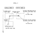
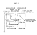
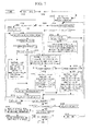
- Figs. 1 and 2 show an example of the reference area set by such methods.
- Fig. 1 shows an example of the process performed when a reference frame used when a reference vector target area was encoded is selected as the current reference frame, and an area which was used as a reference area when encoding the reference vector target area is selected as the reference area in the current reference frame.
- Fig. 2 shows an example of the process performed when a reference vector target frame used when a reference vector target area was encoded is selected as the current reference frame, and an area which was used as a reference vector target area when encoding the current reference vector target area is selected as the reference area in the current reference frame.
- the area which was selected as a reference vector target area or a reference area when encoding the current reference vector target area, was used for predicting the image information of the current reference vector target area, and thus has image information close to the image information of the current reference vector target area.
- such an area belongs to a reference vector target frame or a reference frame, which was used when encoding the current reference vector target area. That is, even when obtaining an area in a reference frame, which corresponds to the reference vector target area, if this reference frame coincides with the relevant frame (i.e., reference vector target frame or reference frame) used in each of the above-described cases, then an area which was selected as a reference vector target area or a reference area when encoding the above reference vector target area is selected.
- the reference area in the reference frame is determined based on encoding information of the reference vector target area, it is possible to reduce the number of execution times of the corresponding-area search, which should be performed in encoding and decoding, while keeping a required quality of the predicted image.
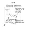
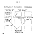
- Figs. 3 to 5 show examples of the reference area set by the above-described methods.
- a unique reference area can be assigned to the encoding target area in either case of (i) when corresponding areas have the same camera or time as shown in Fig. 3 or 4 , or (ii) when corresponding areas have different cameras and different times as shown in Fig. 5 .
- the first assumption is actually effective in most cases because a video image which is often seen, such as a multi-viewpoint video image photographing a target object or a scene, is in the assumed state.
- the second assumption is not generally effective. However, when the interval between the frames is short, it can be assumed that each object generally performs a linear uniform motion, and thus the second assumption can also be effective in most cases. However, the latter assumption may be ineffective when the interval between the frames is long, and thus this method may be applied only when corresponding areas have the same camera or time as shown in Fig. 3 or 4 , or application of this method may be interrupted when the interval between the frames in the relevant corresponding relationship becomes long.
- the reference area is set using the information when encoding the reference vector target area, so as to reduce the number of execution times of the corresponding-area search.
- the reference area set by such a method may not be the most suitable for generating the predicted image of the encoding target area.
- the reference area set by the relevant method may be regarded as a temporary reference area, and only a peripheral area thereof may be subjected to a corresponding-area search so as to improve the possibility of providing an optimum condition for generating the predicted image.
- the relevant methods with a smaller computation cost than that required for a simple corresponding-area search, a corresponding point having an almost equal quality can be found.
- an already-encoded frame different from the reference vector target frame or the reference frame is set as an intermediate frame; an intermediate area, which is a corresponding area in the intermediate frame, is set using the image information or encoding information of the reference vector target area; and then a corresponding area in the reference frame is set using the image information or encoding information of the intermediate area, so as to use the set area as the reference area.
- a narrower search range is required than that required for detecting a corresponding area relating to a temporal change. This is because such an image change due to disparity, which is caused by the arrangement of cameras, appears in a single direction and the amount of change is within a certain limited range.
- the Epipolar geometry constraint is effective, so that an area in an image obtained by one of the cameras is present along a straight line in an image obtained by another one of the cameras. Therefore, it is sufficient to search only a peripheral area of the straight line in consideration of errors in the camera parameters.
- the set intermediate area makes it possible to search for a corresponding area relating to an image change due to one of the time and inter-camera factors in each of the first and second search steps. Accordingly, a corresponding area can be detected by a lower number of computation times in comparison with the direct reference area detection.
- the intermediate frame may be a reference vector target frame used when encoding the reference vector target area, or a reference frame used when encoding the reference vector target area.
- the intermediate area may be a reference vector target area used when encoding the current reference vector target area, or a reference area used when encoding the reference vector target area.
- the image information and encoding information of the intermediate area not only the image information and encoding information of the intermediate area, but also the image information and encoding information of the reference vector target area may also be used.
- the predicted image may be generated using image information of three corresponding areas assigned to the encoding target area, that is, image information of the reference vector target area, image information of the intermediate area, and image information of the reference area.
- a method of computing an average or a median value for each pixel may be used.
- the reference frame and the encoding target frame have a relationship equal to that between the intermediate frame and the reference vector target frame, it can be assumed that a change between the intermediate area and the reference vector target area also occurs between the reference area and the encoding target area, so as to generate the predicted image in accordance with the following formula.
- Pred pix Ref pix + RVec pix - Mid pix
- pix indicates the pixel position in the relevant area
- Pred indicates the predicted image
- Ref indicates the image information of the reference area
- RVec indicates the image information of the reference vector target area
- Mid indicates the image information of the intermediate area.
- information may also be assigned to a method of generating the predicted image by using another area combination, or to each of the predicted image generating methods using the above-described three areas, so as to select the predicted image generating method.
- the information which indicates the predicted image generating method When encoding the information which indicates the predicted image generating method, only the information may be encoded, or the information may be encoded with other information (e.g., reference frame designation information) which should also be encoded. That is, 0 or 1 may be encoded as the reference frame designation information, and 0, 1, or 2 may be encoded as the information for designating the predicted image generating method; or information which indicates any one of (0,0), (0,1), (0,2), (1,0), (1,1), and (1,2) may be encoded for the combination of both information items.
- reference frame designation information e.g., reference frame designation information
- the reference vector target area When the reference vector target area has been encoded without performing interframe video prediction, it represents that no already-encoded frame and no area therein suitable for predicting image information of the reference vector target area can be found. Therefore, also in the encoding target area corresponding to such a reference vector target area, the possibility that an area in a frame other than the reference vector target frame is selected as the area used for generating the predicted image should be small.
- the code corresponding to the information for designating the same frame as the reference vector target frame can be short, so as to reduce the amount of code required for encoding the reference frame designation information.
- the code corresponding to the information for designating a frame which corresponds to the reference frame or the reference vector target frame used when encoding the reference vector target area to which a corresponding relationship has been assigned can also be short so as to further reduce the amount of code required for encoding the reference frame designation information.
- the code word table used when encoding the reference frame designation information can be switched using the encoding information of the reference vector target area so as to encode the reference frame designation information with a reduced amount of code.
- the relevant code word table may be switched using the encoding information of the reference vector target area.
- Fig. 6 shows a video encoding apparatus 100 as an embodiment of the present invention.
- the video encoding apparatus 100 includes an image input unit 101 into which an image as an encoding target is input, a predicted image generator 102 that generates a predicted image using an already-encoded image for each area of a divided encoding target image, a differential image encoder 103 that encodes a differential image between the input image and the predicted image, a differential image decoder 104 that decodes encoded data of the differential image, a reference frame memory 105 that accumulates a decoded image of an encoding target area generated by the sum of the decoded differential image and the predicted image, a reference frame setting unit 106 for selecting a reference frame for generating the predicted image, from the reference frame memory 105, a reference vector target frame setting unit 107 for selecting a reference vector target frame as a reference target (frame) of vector information which is to be encoded, from the reference frame memory 105, a predicted image generating method setting unit 108 for setting a predicted image generating method assigned to an obtained corresponding area, an additional information encoder 109 for
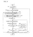
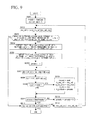
- Fig. 7 shows a flowchart of the video encoding process executed by the video encoding apparatus 100 having the above-described structure.
- a block or frame to which an index is assigned represents a block or frame indicated by the index.
- an image that will become an encoding target is input through the image input unit 101 (S101).
- the input encoding target image is entirely divided into areas, and each area is encoded (S102-S131).
- blk indicates an index of a block (area)
- MaxBlk indicates the total number of blocks for one image.
- a reference vector target frame best_ref_vec, a reference frame best_ref, and a reference vector best_mv_ref for encoding the block; a vector best_mv which indicates a reference area in the reference frame; a predicted image generating method best _pmode; and a predicted reference vector best_pmv are determined (S113 to S126), and a predicted image for the image information of the encoding target area is generated using the above information (S127).
- the encoded data is decoded and a decoded image is stored in the reference frame memory 105.
- the information relating to corresponding areas i.e., two areas such as a reference vector target area indicated by best_mv_ref and a reference area indicated by best_mv) used for generating the predicted image is stored in the corresponding relationship information accumulating memory 112 in association with the number of the encoding target frame and the position of the block blk in the relevant image (S129).
- information used for generating the predicted image for the encoding is obtained by repeatedly executing the following processes (S104-S124) for all already-encoded frames in the reference frame memory 105, which can be used as a reference vector target frame.
- a predicted reference vector pmv is generated using the reference vector in an already-encoded block adjacent to block blk (S104), and a combination of a reference vector, a reference frame, a reference area, and a predicted image generating method is determined, which minimizes the rate-distortion cost when a frame indicated by ref_vec is the reference vector target frame (S105-S124).
- the following steps (S106-S122) are repeatedly executed for all already-encoded frames which are stored in the reference frame memory 105 and can be used as the reference frame.
- the reference vector corresponding to mv_ref_idx is set as mv_ref (S 108)
- the image information of an area at the position "pos + mv_ref" in frame ref is set as a predicted image Pred[] (S109)
- a rate-distortion cost called simply "cost” is computed (S110)
- cost is smaller than bestCost (S111).
- bestCost is rewritten as cost
- best_ref is rewritten as ref
- best_ref_vec is rewritten as ref
- best_ref_mid is rewritten as ref
- best_mv is rewritten as 0 (zero vector)
- best_mv_ref is rewritten as mv_ref
- best_pmode is rewritten as 1
- best_pmv is rewritten as pmv (S112).
- the rate-distortion cost computed in S110 may be obtained by actually encoding the differential image, the differential reference vector "mv_ref - pmv", and the additional information so as to compute the amount of code, and decoding the encoded data so as to compute a quality degradation, thereby performing computation based on the following Formula 2.
- a simplified rate-distortion cost may be computed as the rate-distortion cost based on the following Formula 3.
- a single formula should be used in the process of encoding one block blk.
- ⁇ 1 is an undefined Lagrange multiplier, and is a predetermined value.
- pix indicates the pixel position
- Org[] indicates image information of the encoding target area in the input image
- Dec[] indicates image information of the decoded image.
- bit(vector, ref 1 , ref 2 , mode) is a function which returns the amount of code generated when "vector" as the differential reference vector is encoded
- ref 1 as the reference vector target frame designation information is encoded
- ref 2 as the reference frame designation information is encoded
- mode as the predicted image generating method designation information is encoded.
- ⁇ 2 is an undefined Lagrange multiplier, and is a predetermined value.
- pbit(vector, ref 1 , ref 2 , mode) is a function which returns the amount of code generated when "vector" as the differential reference vector is encoded, ref 1 as the reference vector target frame designation information is encoded, ref 2 as the reference frame designation information is encoded, and "mode" as the predicted image generating method designation information is encoded.
- reference vector b_mv_ref the minimum rate-distortion cost called "mcost" when the frame indicated by ref is the reference frame and the frame indicated by ref_vec is the reference vector target frame (S117).
- mcost the minimum rate-distortion cost
- mcost is smaller than bestCost (S118).
- bestCost is rewritten as mcost
- best_ref is rewritten as ref
- best_ref_vec is rewritten as ref_vec
- best_mv is rewritten as b_mv
- best_mv_ref is rewritten as b_mv_ref
- best_pmode is rewritten as b_pmode
- best_pmv is rewritten as pmv (S119).
- mcost is larger than bestCost, the process in S119 is omitted.
- an already-encoded frame (intermediate frame) is detected where the time and viewpoint relationships between the already-encoded frame and the frame indicated by ref_vec coincide with those between the encoding target frame and the frame indicated by ref, and the index which indicates the already-encoded frame is defined as ref_mid (S115). If no already-encoded frame which satisfies the above condition is present in the reference frame memory 105, ref_mid is set as ref.
- reference vector b_mv_ref which indicates the intermediate area
- vector b_mv which indicates the reference area
- predicted image generating method index b_pmode are determined, which provide the minimum rate-distortion cost "mcost" when the frame indicated by ref is the reference frame
- the frame indicated by ref_vec is the reference vector target frame
- the frame indicated by ref_mid is the intermediate frame (S120). The process of S 120 will be explained in detail later.
- mcost is smaller than bestCost (S 121).
- bestCost is rewritten as mcost
- best_ref is rewritten as ref
- best_ref_vec is rewritten as ref_vec
- best_ref_mid is rewritten as ref_mid
- best_mv is rewritten as b_mv
- best_mv_ref is rewritten as b_mv_ref
- best_mv_mid is rewritten as b_mv_mid
- best_pmode is rewritten as b_pmode
- best_pmv is rewritten as pmv (S122).
- the reason for that S120 is performed after S117 is that the rate-distortion cost may be reduced when generating the intermediate frame.
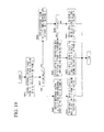
- a reference area is assigned to a currently-set reference vector, and a predicted image generating method for providing a rate-distortion cost most suitable therefor is computed.
- a reference vector to which mv_ref_idx is assigned is obtained, and set as mv_ref (S202).
- a degree of difference between image information of block blk in the input image and image information of an area at the position "pos + mv_ref" in frame ref_vec is computed, and it is determined whether or not the degree is smaller than a predetermined threshold TH (S203).
- the degree of difference between the two image information items may be computed by any method, for example, by computing the sum of absolute differences, the sum of squared differences, or a variance of differences based on the values of corresponding pixels between the relevant two areas, where the threshold TH should be assigned to the employed computing method.
- the degree of difference When the degree of difference is larger than or equal to the threshold, it indicates that the image information of the reference vector target area indicated by mv_ref considerably differ from the image information of the encoding target area, and thus the reference vector target area does not correspond to the encoding target area. Therefore, the operation applied to the current mv_ref_idx is terminated.
- mcost is rewritten as cost
- b_mv_ref is rewritten as mv_ref
- b_mv is rewritten as mv
- b_pmode is rewritten as pmode (S209).
- the computation of the rate-distortion cost in S207 is performed using a method similar to that used in the above-described step S110.
- the maximum value of pmode is set as 2. This is because as the predicted image generating method which can be used when two image information items (image information of the reference vector target frame and image information of the reference frame) are obtained, only two methods are considered as candidates, that is, a method of generating a predicted image using only the image information of the reference frame, and a method of generating a predicted image by computing an average of two image information values for each pair of corresponding pixels. However, the maximum value of pmode may be increased so as to also use another method, for example, for computing the sum of weighted values for the two image information items.
- Pred pix Ref pix + RVec pix + 1 / 2
- a method of generating a predicted image by using only the image information of the reference vector target frame is not employed as a candidate. This is because such a method corresponds to a predicted image generating method when the reference vector target frame is equal to the reference frame.
- a reference area and an intermediate area are assigned to a currently-set reference vector, and a predicted image generating method for providing a rate-distortion cost most suitable therefor is computed.
- the degree of difference When the degree of difference is larger than or equal to the threshold, it indicates that the image information of the reference vector target area indicated by mv_ref considerably differ from the image information of the encoding target area, and thus the reference vector target area does not correspond to the encoding target area. Therefore, the operation applied to the current mv_ref_idx is terminated.
- the area at the position "pos + mv_ref+ mv_mid" in frame ref_mid may be used as the corresponding base area.
- image information used as a template dos not change, and thus it is possible to prevent an error accumulation due to corresponding-area computation, which may provide a corresponding area having image information that does not close to the image information of the encoding target area.
- mcost is rewritten as cost
- b_mv_ref is rewritten as mv_ref
- b_mv_mid is rewritten as mv_mid
- b_mv is rewritten as mv
- b_pmode is rewritten as pmode (S310).
- the computation of the rate-distortion cost in S308 is performed using a method similar to that used in the above-described step S110.
- the predicted image generating method which can be used when three image information items (image information of the reference vector target frame, image information of the reference frame, and image information of the intermediate frame) are obtained, in addition to the methods represented by Formula 4, other three methods are available, that is, a method of generating a predicted image by computing an average of three image information values for each set of corresponding pixels, a method of generating a predicted image by computing a median value of three image information values for each set of corresponding pixels, and a method of generating a predicted image with a assumption such that a change between the intermediate area and the reference vector target area also occurs between the reference area and the encoding target area.
- the three predicted image generating methods can be represented by Formula 5 below.
- another value of pmode may be assigned to another method, or the order of value assignment of pmode may be changed.
- Pred pix Ref pix + RVec pix - Mid pix
- S305 of the relevant flowchart may employ a method of selecting whether the area at the position "pos + mv_ref + mv_mid” in frame ref_mid or the area at the position "pos + mv_ref” in frame ref_vec is used, in accordance with pmode.
- the index of the reference vector target frame used when encoding area AX is retrieved from the corresponding relationship information accumulating memory 112, and is set as ref_vec_t (S401).
- one reference vector target frame used when encoding area AX cannot be specified if, for example, area AX does not coincide with the unit block for encoding.
- the index of a reference vector target frame which is used by the largest part within area AX is set as ref_vec_t.
- ref_vec_t is set at an absolutely unattainable value.
- one reference vector used when encoding area AX cannot be specified if, for example, area AX does not coincide with the unit block for encoding.
- a reference vector which is used by the largest area is set as mv_vec_t.
- the index of the reference frame used when encoding area AX is retrieved from the corresponding relationship information accumulating memory 112, and set as ref_t (S405).
- ref_t is determined using a method similar to that explained in the above-described step S401.
- area Y which belongs to frame B and has image information close to that of area AX is obtained by means of an ordinary search method such as block matching (S409).
- the predicted image is generated by the following Procedure 1 in accordance with pos, best_ref, best_ref_vec, best_ref_mid, best_mv, best_mv_ref, best_mv_mid, and best_pmode, which were obtained through the processes before S127.
- the additional information corresponds to best_ref, best_ref_vec, and best_pmode.
- the differential reference vector is encoded.
- reference vector target frame best_ref_vec is encoded. It is highly possible that the selected best_ref_vec is a frame which has been encoded as best_ref_vec in an adjacent area of block blk, or corresponds to a frame adjacent to the encoding target frame. Therefore, the code word table is switched so that the frame indexes of such frames can be encoded with a smaller amount of code in comparison with encoding of the frame indexes assigned to the other frames. Accordingly, encoding can be performed with a smaller amount of code in comparison with a case in that every frame requires the same amount of code.
- the reference frame best_ref is encoded.
- the code word table is switched using the already-encoded best_ref_vec and the reference vector which can be generated using a differential reference vector which was also encoded separately. That is, by using encoding information of the reference vector target area which belongs to the reference vector target frame best_ref_vec and is indicated by the reference vector, the code word table is switched so that a short-length code word is assigned to a frame index which should appear highly frequently.
- best_pmode is encoded.
- the code word table is switched using the already-encoded best_ref_vec and best_ref, and frame information in the reference frame memory 105.
- ifbest_ref_vec and best_ref coincide with each other, it represents that only one corresponding area can be obtained for block blk, and thus pmode value other than 1 is meaningless.
- the amount of code can be reduced by setting a code word table for omitting the encoding itself of pmode.
- the code word table is switched so that a short-length code word is assigned to each pmode value other than 1, thereby performing encoding with a smaller amount of code in comparison with a case in that a code word having the same length is assigned to every predicted image generating method. Additionally, if only two frames are stored in the reference frame memory, or if no appropriate intermediate frame for the combination of best_ref_vec and best_ref is stored in the reference frame memory 105, then no predicted image generating method which requires three corresponding areas cannot be used.
- the code word table may be switched so that a short-length code word is assigned to the other predicted image generating methods, thereby performing encoding with a smaller amount of code in comparison with a case in that a code word having the same length is assigned to every predicted image generating method.
- the items of additional information may be individually encoded, or a number may be assigned to each combination thereof so as to encode the number.
- the set of ⁇ best_ref, best_ref_vec, best_pmode ⁇ has 20 value combinations such as ⁇ 1,1,1 ⁇ , ⁇ 1,1,2 ⁇ , ⁇ 1,1,3 ⁇ , ⁇ 1,1,4 ⁇ , ⁇ 1,1,5 ⁇ , ⁇ 1,2,1 ⁇ , ⁇ 1,2,2 ⁇ , ⁇ 1,2,3 ⁇ , ⁇ 1,2,4 ⁇ , ⁇ 1,2,5 ⁇ , ⁇ 2,1,1 ⁇ , ⁇ 2,1,2 ⁇ , ⁇ 2,1,3 ⁇ , ⁇ 2,1,4 ⁇ , ⁇ 2,1,5 ⁇ , ⁇ 2,2,1 ⁇ , ⁇ 2,2,2 ⁇ , ⁇ 2,3 ⁇ , ⁇ 2,2,4 ⁇ , and ⁇ 2,2,5 ⁇ .
- numbers 1 to 20 may be assigned and encoded.
- the reference frame memory includes only two images, no frame can be selected as an intermediate frame, and thus each pmode value which requires three corresponding areas is meaningless. Therefore, effective combinations are further reduced, and only 6 combinations such as ⁇ 1,1,1 ⁇ , ⁇ 1,2,1 ⁇ , ⁇ 1,2,2 ⁇ , ⁇ 2,1,1 ⁇ , ⁇ 2,1,2 ⁇ , and ⁇ 2,2,1 ⁇ are effective. In such a case, one of the numbers 1 to 6 should be encoded.
- best_ref_vec may be individually encoded while best_ref and pmode may be combined so as to encode them using one code word.
- an encoding method by switching the code word table for ⁇ best_ref, pmode ⁇ in accordance with encoded data of a reference vector target area (which is obtained using best_ref_vec and a reference vector which has been separately encoded) can be easily inferred.
- Fig. 11 shows a video decoding apparatus 200 as an embodiment of the present invention.
- the video decoding apparatus 200 includes a differential image decoder 201 that decodes encoded data of a differential image with respect to a predicted image of an image that becomes a decoding target, a differential reference vector decoder 202 that decodes encoded data of a differential reference vector as the difference between a reference vector, which is necessary for generating a predicted image, and a predicted reference vector, an additional information decoder 203 that decodes encoded data of additional information consisting of reference vector target frame designation information, reference frame designation information, and predicted image generating method designation information, which are necessary for generating the predicted image, a predicted image generator 204 that generates a predicted image of a decoding target area in accordance with provided information, a reference frame memory 205 that accumulates a decoded image determined from the sum of a predicted image and a decoded differential image, a predicted reference vector generator 206 that generates a predicted reference vector as a predicted vector of the reference vector used in the decoding target area, based on vector information which was used in an area
- Fig. 12 shows a flowchart of the video decoding process executed by the video decoding apparatus 200 having the above-described structure.
- the video decoding process executed by the above-configured video decoding apparatus 200 will be explained in detail, where it is assumed that images of a plurality of frames are already decoded, and the results thereof have been stored in the reference frame memory 205 and the corresponding relationship information accumulating memory 207.
- encoded data of a differential image, encoded data of the differential reference vector, and encoded data of the additional information are input to the video decoding apparatus 200, and sent respectively to the differential image decoder 201, the differential reference vector decoder 202, and the additional information decoder 203 (S501).
- the decoding target image is entirely divided into areas, and each area is decoded (S502 to S517).
- blk indicates an index of a block (area)
- MaxBlk indicates the total number of blocks in one image.
- the position of block blk is stored as "pos” (S503), and predicted reference vector "pmv” is generated using, for example, a reference vector which is stored in the corresponding relationship information accumulating memory 207 and was used in a peripheral block around block blk (S504).
- reference vector target frame index dec_ref_vec reference frame index dec_ref
- predicted image generating method index dec_pmode predicted image generating method index dec_pmode
- differential reference vector dec_sub_mv_ref image information Res[] of a predicted residual image for block blk
- the reference vector dec_mv_ref is obtained by computing "pmv+dec_sub_mv_ref"
- mv is initialized at zero vector (S505).
- dec_ref coincides with dec_ref_vec (S506). If it is determined that they coincide with each other, predicted image Pred[] is generated (S512).
- the predicted image generating process performed here is performed in accordance with the above-described Procedure 1 while best_ref is regarded as dec_ref, best_ref_vec is regarded as dec_ref_vec, best_mv_ref is regarded as dec_mv_ref, best_mode is regarded as dec_pmode, best_ref_mid is regarded as ref_mid, best_mv_mid is regarded as mv_mid, and best_mv is regarded as mv in Procedure 1.
- dec_ref does not coincide with dec_ref_vec
- an already-decoded frame is detected where the time and viewpoint relationships between the already-decoded frame and the frame indicated by dec_ref_vec coincide with those between the decoding target frame and the frame indicated by dec_ref, and the index which indicates the already-decoded frame is defined as ref_mid (S507). If no already-decoded frame which satisfies the above condition is present in the reference frame memory 205, ref_mid is set as dec_ref.
- an area which belongs to frame dec_ref and corresponds to the area at the position "pos + dec_mv_ref” in frame dec_ref_vec, is computed, and "mv” is computed for setting the position of the computed area as "pos + dec_mv_ref + mv” (S509).
- This process is equal to that performed in the above-described step S204 except that the names of some variables are different between the steps.
- an area which belongs to frame dec_ref and corresponds to the area at the position "pos + dec_mv_ref + mv_mid" in frame ref_mid, is computed, and "mv” is computed for setting the position of the computed area as "pos + dec_mv_ref + mv” (S3511).
- the above process is equal to that performed in the above-described steps S304 and S305 except that the names of some variables are different between the corresponding steps.
- predicted image Pred[] is generated using the obtained information (S512).
- the predicted image generating process performed here is executed in accordance with the above-described Procedure 1 while best_ref is regarded as dec_ref, best_ref _vec is regarded as dec_ref_vec, best_mv_ref is regarded as dec_mv_ref, best_pmode is regarded as dec_pmode, best_ref_mid is regarded as ref_mid, best_mv_mid is regarded as mv_mid, and best_mv is regarded as mv in Procedure 1.
- dec_ref_vec, dec_ref, dec_mv_ref, dec_pmode, and mv which were used for the decoding, are stored in the corresponding relationship information accumulating memory 207 in association with the index of the decoding target frame and "pos" (or blk) (S515).
- the decoding is performed while switching the code word table, similar to the above-described methods for encoding.
- encoded data of the differential reference vector is decoded, and thus the reference vector used in block blk is already obtained.
- dec_ref_vec is decoded. It is highly possible that the frame indicated by dec_ref_vec is a frame which was used as a reference vector target frame in an adjacent area of block blk, or corresponds to a frame adjacent to the encoding target frame. Therefore, it is also highly possible that the frame indexes corresponding to such frames have been encoded, and the code word table is switched so that shorter-length code words are assigned to the relevant frame indexes in comparison with those assigned to the frame indexes corresponding to the other frames.
- dec_ref is encoded.
- the code word table is switched using the already-decoded dec_ref_vec and the reference vector. That is, by using encoding information of the reference vector target area which belongs to the frame dec_ref_vec and is indicated by the reference vector, the code word table is switched so that a short-length code word is assigned to a frame index which should appear frequently.
- dec_ref becomes equal to dec_ref_vec.
- a code word table in which a short-length code word is assigned to the same frame index as dec_ref_vec is used.
- the wider the used part of the relevant frame the higher the probability that the relevant frame is selected as dec_ref. Therefore, a code word table in which a code word is assigned to the frame in accordance with the relevant probability is used.
- dec_pmode is decoded.
- the code word table is switched using the already-decoded dec_ref_vec and dec_ref, and frame information in the reference frame memory 205. For example, if dec_ref_vec and dec_ref coincide with each other, it represents that only one corresponding area can be obtained for block blk, and thus dec_pmode value other than 1 is meaningless. Therefore, it is determined that dec_pmode is not included in the encoded data, and the decoded value thereof is set as 1.
- dec_ref_vec and dec_ref do not coincide with each other, the possibility that 1 is selected as dec_pmode should be very low. Therefore, a code word table in which a short-length code word is assigned to each dec_pmode value other than 1 is used. Additionally, if only two frames are stored in the reference frame memory, or if no appropriate intermediate frame for the combination of dec_ref_vec and dec_ref is stored in the reference frame memory 205, then no predicted image generating method which requires three corresponding areas cannot be used. Therefore, the code word table is switched so that a short-length code word is assigned to the other predicted image generating methods.
- code word table and the criterion for switching the table employed here should correspond to those employed in the corresponding encoding.
- a number may be assigned to each combination thereof so as to encode the number.
- the decoding is also performed by regarding that a number has been assigned to each combination.
- the intermediate frame is always a frame which satisfies that the time and viewpoint relationships between this frame and the reference vector target frame coincide with those between the encoding or decoding target frame and the reference frame.
- a frame defined by another condition may be used while the encoding and decoding sides should have the same condition.
- the intermediate frame may be set to one of (i) a frame having a display time equal to that of the reference vector target frame and viewpoint information equal to that of the reference frame, and (ii) a frame having a display time equal to that of the reference frame and viewpoint information equal to that of the reference vector target frame, where between the two frames, one having the display time and the viewpoint information closer to those of the encoding or decoding target frame is selected.
- an image variation from the reference vector target frame to the intermediate frame and an image variation from the intermediate frame to the reference frame are each caused by any one of a temporal factor or a camera factor, so that the amount of computation required for searching for a corresponding area can be reduced.
- (i) another condition may be applied such that the relevant predicted image generating method can be selected only when satisfying the condition assumed by the predicted image generating method such that the relationship between the reference frame and the encoding target frame coincides with that between the intermediate frame (selected by the relevant method) and the reference vector target frame, or (ii) the code word table may be switched depending on whether or not such an assumed condition is satisfied, so as to assign a shorter-length code word to a predicted image generating method which is more often selected than other methods.
- the embodiments do not mention intraframe encoding, it can easily be added as a method of generating a predicted image by, for example, allocating another number as the predicted image generating method.
- a video encoding apparatus or a video decoding apparatus implemented by separately providing encoding modes (as in H.264) instead of providing predicted image generating methods can also be easily inferred from the present invention.
- the video encoding and decoding processes as described above can also be implemented by a computer program.
- a computer program may be provided by storing it in an appropriate computer-readable storage medium, or by means of a network.
- the video encoding and decoding methods of the present invention can be implemented using the steps corresponding to the operation of each unit included in the video encoding and decoding apparatuses.
- the same reference vector target frame is used, so that the primary factor (time or disparity) which causes an image variation and should be represented by a vector is unified, and a predicted vector close to a vector which should be encoded can be generated using an already-encoded vector in an adjacent area. Therefore, vector information for interframe predictive encoding can be encoded with a reduced amount of code.
Landscapes
- Engineering & Computer Science (AREA)
- Multimedia (AREA)
- Signal Processing (AREA)
- Compression Or Coding Systems Of Tv Signals (AREA)
Priority Applications (1)
| Application Number | Priority Date | Filing Date | Title |
|---|---|---|---|
| EP20120173486 EP2512139B1 (de) | 2006-10-30 | 2007-10-24 | Videocodierungsverfahren und -decodierungsverfahren, Vorrichtungen dafür, Programme dafür und Speichermedien zum Speichern der Programme |
Applications Claiming Priority (2)
| Application Number | Priority Date | Filing Date | Title |
|---|---|---|---|
| JP2006293901 | 2006-10-30 | ||
| PCT/JP2007/070711 WO2008053758A1 (fr) | 2006-10-30 | 2007-10-24 | Procédé de codage d'image dynamique, procédé de décodage, leur dispositif, leur programme et support de stockage contenant le programme |
Related Child Applications (1)
| Application Number | Title | Priority Date | Filing Date |
|---|---|---|---|
| EP20120173486 Division EP2512139B1 (de) | 2006-10-30 | 2007-10-24 | Videocodierungsverfahren und -decodierungsverfahren, Vorrichtungen dafür, Programme dafür und Speichermedien zum Speichern der Programme |
Publications (2)
| Publication Number | Publication Date |
|---|---|
| EP2083571A1 true EP2083571A1 (de) | 2009-07-29 |
| EP2083571A4 EP2083571A4 (de) | 2010-11-10 |
Family
ID=39344100
Family Applications (2)
| Application Number | Title | Priority Date | Filing Date |
|---|---|---|---|
| EP20120173486 Active EP2512139B1 (de) | 2006-10-30 | 2007-10-24 | Videocodierungsverfahren und -decodierungsverfahren, Vorrichtungen dafür, Programme dafür und Speichermedien zum Speichern der Programme |
| EP20070830445 Ceased EP2083571A4 (de) | 2006-10-30 | 2007-10-24 | Dynamisches bildkodierungsverfahren, dekodierungsverfahren, einrichtung dafür, programm dafür und das programm enthaltendes speichermedium |
Family Applications Before (1)
| Application Number | Title | Priority Date | Filing Date |
|---|---|---|---|
| EP20120173486 Active EP2512139B1 (de) | 2006-10-30 | 2007-10-24 | Videocodierungsverfahren und -decodierungsverfahren, Vorrichtungen dafür, Programme dafür und Speichermedien zum Speichern der Programme |
Country Status (11)
| Country | Link |
|---|---|
| US (2) | US8532190B2 (de) |
| EP (2) | EP2512139B1 (de) |
| JP (1) | JP4999860B2 (de) |
| KR (2) | KR101447717B1 (de) |
| CN (1) | CN101569202B (de) |
| BR (1) | BRPI0718272A2 (de) |
| CA (1) | CA2667175A1 (de) |
| ES (1) | ES2439444T3 (de) |
| RU (2) | RU2458479C2 (de) |
| TW (2) | TWI502969B (de) |
| WO (1) | WO2008053758A1 (de) |
Cited By (1)
| Publication number | Priority date | Publication date | Assignee | Title |
|---|---|---|---|---|
| TWI461052B (zh) * | 2010-02-23 | 2014-11-11 | Nippon Telegraph & Telephone | 移動向量推估方法、多視點影像編碼方法、多視點影像解碼方法、移動向量推估裝置、多視點影像編碼裝置、多視點影像解碼裝置、移動向量推估程式、多視點影像編碼程式及多視點影像解碼程式 |
Families Citing this family (66)
| Publication number | Priority date | Publication date | Assignee | Title |
|---|---|---|---|---|
| KR101158491B1 (ko) | 2008-12-08 | 2012-06-20 | 한국전자통신연구원 | 다시점 영상 부호화, 복호화 방법 및 그 장치. |
| PH12013500092A1 (en) * | 2010-07-15 | 2017-05-05 | Velos Media Int Ltd | Image intra-prediction mode estimation device, image encoding device, image decoding device, and encoded image data |
| JP5281632B2 (ja) * | 2010-12-06 | 2013-09-04 | 日本電信電話株式会社 | 多視点画像符号化方法,多視点画像復号方法,多視点画像符号化装置,多視点画像復号装置およびそれらのプログラム |
| US20120189060A1 (en) * | 2011-01-20 | 2012-07-26 | Industry-Academic Cooperation Foundation, Yonsei University | Apparatus and method for encoding and decoding motion information and disparity information |
| RU2480941C2 (ru) | 2011-01-20 | 2013-04-27 | Корпорация "Самсунг Электроникс Ко., Лтд" | Способ адаптивного предсказания кадра для кодирования многоракурсной видеопоследовательности |
| KR20120095610A (ko) * | 2011-02-21 | 2012-08-29 | 삼성전자주식회사 | 다시점 비디오의 부호화 방법 및 장치, 그 복호화 방법 및 장치 |
| JP5747559B2 (ja) * | 2011-03-01 | 2015-07-15 | 富士通株式会社 | 動画像復号方法、動画像符号化方法、動画像復号装置、及び動画像復号プログラム |
| JP5664762B2 (ja) * | 2011-03-17 | 2015-02-04 | 富士通株式会社 | 動画像復号方法、動画像符号化方法、動画像復号装置及び動画像復号プログラム |
| US20120268551A1 (en) * | 2011-04-19 | 2012-10-25 | Ben Wu | Image Interaction Device, Interactive Image Operating System, and Interactive Image Operating Method thereof |
| US9247249B2 (en) * | 2011-04-20 | 2016-01-26 | Qualcomm Incorporated | Motion vector prediction in video coding |
| US9366448B2 (en) | 2011-06-20 | 2016-06-14 | Honeywell International Inc. | Method and apparatus for configuring a filter change notification of an HVAC controller |
| JPWO2012176684A1 (ja) * | 2011-06-22 | 2015-02-23 | ソニー株式会社 | 画像処理装置および方法 |
| JP6112418B2 (ja) | 2011-06-29 | 2017-04-12 | サン パテント トラスト | 画像符号化方法、画像復号方法、画像符号化装置、画像復号装置および画像符号化復号装置 |
| WO2013001749A1 (ja) * | 2011-06-29 | 2013-01-03 | パナソニック株式会社 | 画像符号化方法、画像復号方法、画像符号化装置、画像復号装置および画像符号化復号装置 |
| US8892223B2 (en) | 2011-09-07 | 2014-11-18 | Honeywell International Inc. | HVAC controller including user interaction log |
| JP6039178B2 (ja) * | 2011-09-15 | 2016-12-07 | シャープ株式会社 | 画像符号化装置、画像復号装置、並びにそれらの方法及びプログラム |
| JP2013102297A (ja) * | 2011-11-07 | 2013-05-23 | Canon Inc | 画像符号化方法、画像符号化装置及びプログラム、画像復号方法、画像復号装置及びプログラム |
| US9206993B2 (en) | 2011-12-14 | 2015-12-08 | Honeywell International Inc. | HVAC controller with utility saver switch diagnostic feature |
| US10533761B2 (en) | 2011-12-14 | 2020-01-14 | Ademco Inc. | HVAC controller with fault sensitivity |
| US10747243B2 (en) | 2011-12-14 | 2020-08-18 | Ademco Inc. | HVAC controller with HVAC system failure detection |
| US9002523B2 (en) | 2011-12-14 | 2015-04-07 | Honeywell International Inc. | HVAC controller with diagnostic alerts |
| JP2013126093A (ja) * | 2011-12-14 | 2013-06-24 | Sony Corp | 画像処理装置及び画像処理方法 |
| US8902071B2 (en) | 2011-12-14 | 2014-12-02 | Honeywell International Inc. | HVAC controller with HVAC system fault detection |
| US20130158720A1 (en) | 2011-12-15 | 2013-06-20 | Honeywell International Inc. | Hvac controller with performance log |
| US9560353B2 (en) * | 2012-01-27 | 2017-01-31 | Sun Patent Trust | Video encoding method, video encoding device, video decoding method and video decoding device |
| US10139843B2 (en) | 2012-02-22 | 2018-11-27 | Honeywell International Inc. | Wireless thermostatic controlled electric heating system |
| KR20140133770A (ko) * | 2012-02-23 | 2014-11-20 | 가부시키가이샤 스퀘어.에닉스.홀딩스 | 동화상 배신 서버, 동화상 재생 장치, 제어 방법, 및 컴퓨터 판독 가능한 기록 매체 |
| US9442500B2 (en) | 2012-03-08 | 2016-09-13 | Honeywell International Inc. | Systems and methods for associating wireless devices of an HVAC system |
| US10452084B2 (en) | 2012-03-14 | 2019-10-22 | Ademco Inc. | Operation of building control via remote device |
| US9488994B2 (en) | 2012-03-29 | 2016-11-08 | Honeywell International Inc. | Method and system for configuring wireless sensors in an HVAC system |
| WO2013162273A1 (ko) * | 2012-04-24 | 2013-10-31 | 엘지전자 주식회사 | 비디오 신호 처리 방법 및 장치 |
| RU2506712C1 (ru) * | 2012-06-07 | 2014-02-10 | Корпорация "САМСУНГ ЭЛЕКТРОНИКС Ко., Лтд." | Способ межкадрового прогнозирования для кодирования многоракурсной видеопоследовательности |
| WO2014010464A1 (ja) * | 2012-07-10 | 2014-01-16 | シャープ株式会社 | 予測ベクトル生成装置、画像符号化装置、画像復号装置、予測ベクトル生成方法、およびプログラム |
| US9594384B2 (en) | 2012-07-26 | 2017-03-14 | Honeywell International Inc. | Method of associating an HVAC controller with an external web service |
| US9477239B2 (en) | 2012-07-26 | 2016-10-25 | Honeywell International Inc. | HVAC controller with wireless network based occupancy detection and control |
| JP2014027448A (ja) * | 2012-07-26 | 2014-02-06 | Sony Corp | 情報処理装置、情報処理方法、及びプログラム |
| US9020282B2 (en) * | 2012-12-28 | 2015-04-28 | Intel Corporation | Coder based partial image storage and retrieval |
| US10094585B2 (en) | 2013-01-25 | 2018-10-09 | Honeywell International Inc. | Auto test for delta T diagnostics in an HVAC system |
| JP6139953B2 (ja) * | 2013-04-12 | 2017-05-31 | 日本電信電話株式会社 | 映像符号化方法、映像復号方法、映像符号化装置、映像復号装置、映像符号化プログラム、映像復号プログラム及び記録媒体 |
| US9584119B2 (en) | 2013-04-23 | 2017-02-28 | Honeywell International Inc. | Triac or bypass circuit and MOSFET power steal combination |
| US9806705B2 (en) | 2013-04-23 | 2017-10-31 | Honeywell International Inc. | Active triac triggering circuit |
| US9983244B2 (en) | 2013-06-28 | 2018-05-29 | Honeywell International Inc. | Power transformation system with characterization |
| US10811892B2 (en) | 2013-06-28 | 2020-10-20 | Ademco Inc. | Source management for a power transformation system |
| US11054448B2 (en) | 2013-06-28 | 2021-07-06 | Ademco Inc. | Power transformation self characterization mode |
| US9628795B2 (en) * | 2013-07-17 | 2017-04-18 | Qualcomm Incorporated | Block identification using disparity vector in video coding |
| US9426465B2 (en) * | 2013-08-20 | 2016-08-23 | Qualcomm Incorporated | Sub-PU level advanced residual prediction |
| KR20160045121A (ko) * | 2013-10-17 | 2016-04-26 | 니폰 덴신 덴와 가부시끼가이샤 | 영상 부호화 장치 및 방법, 및 영상 복호 장치 및 방법 |
| KR101792089B1 (ko) | 2013-10-17 | 2017-11-01 | 니폰 덴신 덴와 가부시끼가이샤 | 영상 부호화 장치 및 방법, 및 영상 복호 장치 및 방법 |
| WO2015056712A1 (ja) | 2013-10-17 | 2015-04-23 | 日本電信電話株式会社 | 動画像符号化方法、動画像復号方法、動画像符号化装置、動画像復号装置、動画像符号化プログラム、及び動画像復号プログラム |
| US9857091B2 (en) | 2013-11-22 | 2018-01-02 | Honeywell International Inc. | Thermostat circuitry to control power usage |
| US9673811B2 (en) | 2013-11-22 | 2017-06-06 | Honeywell International Inc. | Low power consumption AC load switches |
| KR20160079068A (ko) * | 2013-12-03 | 2016-07-05 | 니폰 덴신 덴와 가부시끼가이샤 | 영상 부호화 장치 및 방법, 영상 복호 장치 및 방법, 및 그 프로그램 |
| US10649418B2 (en) | 2013-12-11 | 2020-05-12 | Ademco Inc. | Building automation controller with configurable audio/visual cues |
| WO2015098827A1 (ja) * | 2013-12-27 | 2015-07-02 | 日本電信電話株式会社 | 映像符号化方法、映像復号方法、映像符号化装置、映像復号装置、映像符号化プログラム及び映像復号プログラム |
| US20170019683A1 (en) * | 2014-03-20 | 2017-01-19 | Nippon Telegraph And Telephone Corporation | Video encoding apparatus and method and video decoding apparatus and method |
| US9939253B2 (en) * | 2014-05-22 | 2018-04-10 | Brain Corporation | Apparatus and methods for distance estimation using multiple image sensors |
| US9628074B2 (en) | 2014-06-19 | 2017-04-18 | Honeywell International Inc. | Bypass switch for in-line power steal |
| US9683749B2 (en) | 2014-07-11 | 2017-06-20 | Honeywell International Inc. | Multiple heatsink cooling system for a line voltage thermostat |
| JP5858119B2 (ja) * | 2014-10-15 | 2016-02-10 | 富士通株式会社 | 動画像復号方法、動画像符号化方法、動画像復号装置及び動画像復号プログラム |
| EP3171598A1 (de) * | 2015-11-19 | 2017-05-24 | Thomson Licensing | Verfahren und vorrichtung zur codierung und decodierung einer matrix von ansichten aus lichtfelddaten, entsprechendes computerprogramm und nichttransitorische programmspeichervorrichtung |
| US10488062B2 (en) | 2016-07-22 | 2019-11-26 | Ademco Inc. | Geofence plus schedule for a building controller |
| CN107872671B (zh) * | 2016-09-26 | 2022-01-14 | 华为技术有限公司 | 一种图片编码方法及终端 |
| US11665365B2 (en) * | 2018-09-14 | 2023-05-30 | Google Llc | Motion prediction coding with coframe motion vectors |
| CN110636334B (zh) * | 2019-08-23 | 2022-12-09 | 西安万像电子科技有限公司 | 数据传输方法及系统 |
| US20240179345A1 (en) * | 2021-03-30 | 2024-05-30 | Interdigital Ce Patent Holdings, Sas | Externally enhanced prediction for video coding |
| CN121925852A (zh) * | 2023-09-25 | 2026-04-24 | 抖音视界有限公司 | 用于视频处理的方法、装置和介质 |
Family Cites Families (36)
| Publication number | Priority date | Publication date | Assignee | Title |
|---|---|---|---|---|
| JPH0232486A (ja) * | 1988-07-22 | 1990-02-02 | Fuji Electric Co Ltd | 経時的収集データ欠損時の自動修復方法 |
| JPH0262180A (ja) * | 1988-08-26 | 1990-03-02 | Fujitsu Ltd | 動画像の動き補償予測符号化方式 |
| JPH05225152A (ja) * | 1992-02-13 | 1993-09-03 | Hitachi Ltd | プロセスコントローラ |
| DE69430877T2 (de) | 1993-04-09 | 2003-02-06 | Sony Corp., Tokio/Tokyo | Bildkodierungsverfahren und -vorrichtung |
| JP3170958B2 (ja) * | 1993-06-30 | 2001-05-28 | 日産自動車株式会社 | 情報収集方法 |
| JP3383092B2 (ja) * | 1994-09-14 | 2003-03-04 | 東芝システムテクノロジー株式会社 | プラント性能計算装置 |
| US6275532B1 (en) * | 1995-03-18 | 2001-08-14 | Sharp Kabushiki Kaisha | Video coding device and video decoding device with a motion compensated interframe prediction |
| DE69619002T2 (de) * | 1995-03-10 | 2002-11-21 | Kabushiki Kaisha Toshiba, Kawasaki | Bildkodierungs-/-dekodierungsvorrichtung |
| JPH09261653A (ja) * | 1996-03-18 | 1997-10-03 | Sharp Corp | 多視点画像符号化装置 |
| JP3693407B2 (ja) * | 1996-04-04 | 2005-09-07 | シャープ株式会社 | 多視点画像符号化装置および復号装置 |
| JP3823370B2 (ja) * | 1996-04-15 | 2006-09-20 | ソニー株式会社 | 動画像符号化方法、復号方法及びその装置 |
| JP3628810B2 (ja) | 1996-06-28 | 2005-03-16 | 三菱電機株式会社 | 画像符号化装置 |
| JPH1049203A (ja) * | 1996-07-29 | 1998-02-20 | Fuji Electric Co Ltd | 定周期収集データの等値化装置 |
| JPH10276481A (ja) * | 1997-03-31 | 1998-10-13 | Omron Corp | ワイヤレス稼動情報収集方法および装置 |
| US6690835B1 (en) * | 1998-03-03 | 2004-02-10 | Interuniversitair Micro-Elektronica Centrum (Imec Vzw) | System and method of encoding video frames |
| JP2000261467A (ja) * | 1999-03-09 | 2000-09-22 | Toshiba Corp | 情報収集装置 |
| JP3684565B2 (ja) * | 1999-03-29 | 2005-08-17 | 横河電機株式会社 | 分散オブジェクトシステムにおける通信装置 |
| JP2003015735A (ja) * | 2001-07-05 | 2003-01-17 | Mitsubishi Electric Corp | プラント監視・通報装置 |
| JP2003076405A (ja) * | 2001-08-30 | 2003-03-14 | Digital Electronics Corp | 制御用表示装置、制御システム、制御プログラムおよびそれを記録した記録媒体 |
| RU2237283C2 (ru) | 2001-11-27 | 2004-09-27 | Самсунг Электроникс Ко., Лтд. | Устройство и способ представления трехмерного объекта на основе изображений с глубиной |
| KR100481732B1 (ko) * | 2002-04-20 | 2005-04-11 | 전자부품연구원 | 다 시점 동영상 부호화 장치 |
| KR100491530B1 (ko) * | 2002-05-03 | 2005-05-27 | 엘지전자 주식회사 | 모션 벡터 결정 방법 |
| JP2004023458A (ja) * | 2002-06-17 | 2004-01-22 | Toshiba Corp | 動画像符号化/復号化方法及び装置 |
| JP3934568B2 (ja) * | 2003-03-04 | 2007-06-20 | 松下電器産業株式会社 | 動画符号化方法および装置 |
| JP3997171B2 (ja) * | 2003-03-27 | 2007-10-24 | 株式会社エヌ・ティ・ティ・ドコモ | 動画像符号化装置、動画像符号化方法、動画像符号化プログラム、動画像復号装置、動画像復号方法、及び動画像復号プログラム |
| JP4373702B2 (ja) * | 2003-05-07 | 2009-11-25 | 株式会社エヌ・ティ・ティ・ドコモ | 動画像符号化装置、動画像復号化装置、動画像符号化方法、動画像復号化方法、動画像符号化プログラム及び動画像復号化プログラム |
| US7286689B2 (en) * | 2003-06-07 | 2007-10-23 | Hewlett-Packard Development Company, L.P. | Motion estimation for compression of calibrated multi-view image sequences |
| JP2005038246A (ja) * | 2003-07-16 | 2005-02-10 | Matsushita Electric Works Ltd | 設備監視制御装置、設備監視制御システム、設備監視制御方法及び設備監視制御用プログラム |
| US7778328B2 (en) | 2003-08-07 | 2010-08-17 | Sony Corporation | Semantics-based motion estimation for multi-view video coding |
| KR100517517B1 (ko) * | 2004-02-20 | 2005-09-28 | 삼성전자주식회사 | 중간 시점 영상 합성 방법 및 그를 적용한 3d 디스플레이장치 |
| KR100679740B1 (ko) | 2004-06-25 | 2007-02-07 | 학교법인연세대학교 | 시점 선택이 가능한 다시점 동영상 부호화/복호화 방법 |
| WO2006016418A1 (ja) * | 2004-08-11 | 2006-02-16 | Hitachi, Ltd. | 符号化ストリーム記録媒体、画像符号化装置、及び画像復号化装置 |
| TWI268715B (en) * | 2004-08-16 | 2006-12-11 | Nippon Telegraph & Telephone | Picture encoding method, picture decoding method, picture encoding apparatus, and picture decoding apparatus |
| CN100584013C (zh) | 2005-01-07 | 2010-01-20 | 日本电信电话株式会社 | 视频编码方法及装置、视频解码方法及装置 |
| JP2006285353A (ja) * | 2005-03-31 | 2006-10-19 | Daikin Ind Ltd | 機器管理システム |
| JP2006293901A (ja) | 2005-04-14 | 2006-10-26 | Fujitsu Ten Ltd | 車載システム及び車載端末 |
-
2007
- 2007-10-24 JP JP2008542061A patent/JP4999860B2/ja active Active
- 2007-10-24 BR BRPI0718272-4A2A patent/BRPI0718272A2/pt not_active IP Right Cessation
- 2007-10-24 CN CN2007800479423A patent/CN101569202B/zh active Active
- 2007-10-24 RU RU2009115654/07A patent/RU2458479C2/ru active
- 2007-10-24 EP EP20120173486 patent/EP2512139B1/de active Active
- 2007-10-24 ES ES12173486T patent/ES2439444T3/es active Active
- 2007-10-24 KR KR1020097008596A patent/KR101447717B1/ko active Active
- 2007-10-24 US US12/445,446 patent/US8532190B2/en active Active
- 2007-10-24 CA CA 2667175 patent/CA2667175A1/en not_active Abandoned
- 2007-10-24 KR KR1020147006050A patent/KR101533740B1/ko active Active
- 2007-10-24 EP EP20070830445 patent/EP2083571A4/de not_active Ceased
- 2007-10-24 WO PCT/JP2007/070711 patent/WO2008053758A1/ja not_active Ceased
- 2007-10-26 TW TW101112971A patent/TWI502969B/zh active
- 2007-10-26 TW TW96140159A patent/TWI400959B/zh active
-
2012
- 2012-03-15 US US13/421,133 patent/US8654854B2/en active Active
- 2012-04-06 RU RU2012113724/08A patent/RU2504106C2/ru active
Non-Patent Citations (6)
| Title |
|---|
| H-S KOO ET AL: "MVC motion from neighbor view" ITU STUDY GROUP 16 - VIDEO CODING EXPERTS GROUP -ISO/IEC MPEG & ITU-T VCEG(ISO/IEC JTC1/SC29/WG11 AND ITU-T SG16 Q6), XX, XX, no. JVT-U091, 22 October 2006 (2006-10-22) , XP030006737 * |
| LEE S H ET AL: "Inter-view motion info copy methods in MVC" ITU STUDY GROUP 16 - VIDEO CODING EXPERTS GROUP -ISO/IEC MPEG & ITU-T VCEG(ISO/IEC JTC1/SC29/WG11 AND ITU-T SG16 Q6), XX, XX, no. JVT-T135, 18 July 2006 (2006-07-18), XP030006622 * |
| MERKLE P ET AL: "Efficient Compression of Multi-View Video Exploiting Inter-View Dependencies Based on H.264/MPEG4-AVC" MULTIMEDIA AND EXPO, 2006 IEEE INTERNATIONAL CONFERENCE ON, IEEE, PI LNKD- DOI:10.1109/ICME.2006.262881, 1 July 2006 (2006-07-01), pages 1717-1720, XP031033186 ISBN: 978-1-4244-0366-0 * |
| See also references of WO2008053758A1 * |
| S-H LEE ET AL: "Disparity vector prediction methods in MVC" ITU STUDY GROUP 16 - VIDEO CODING EXPERTS GROUP -ISO/IEC MPEG & ITU-T VCEG(ISO/IEC JTC1/SC29/WG11 AND ITU-T SG16 Q6),, no. JVT-U040, 20 October 2006 (2006-10-20), XP007913064 * |
| YAN H ET AL: "MVC region disparity based motion & disparity" ITU STUDY GROUP 16 - VIDEO CODING EXPERTS GROUP -ISO/IEC MPEG & ITU-T VCEG(ISO/IEC JTC1/SC29/WG11 AND ITU-T SG16 Q6), XX, XX, no. JVT-V071, 14 January 2007 (2007-01-14) , XP030006879 * |
Cited By (1)
| Publication number | Priority date | Publication date | Assignee | Title |
|---|---|---|---|---|
| TWI461052B (zh) * | 2010-02-23 | 2014-11-11 | Nippon Telegraph & Telephone | 移動向量推估方法、多視點影像編碼方法、多視點影像解碼方法、移動向量推估裝置、多視點影像編碼裝置、多視點影像解碼裝置、移動向量推估程式、多視點影像編碼程式及多視點影像解碼程式 |
Also Published As
| Publication number | Publication date |
|---|---|
| KR20140048320A (ko) | 2014-04-23 |
| RU2458479C2 (ru) | 2012-08-10 |
| EP2512139B1 (de) | 2013-09-11 |
| BRPI0718272A2 (pt) | 2013-11-12 |
| US20100008422A1 (en) | 2010-01-14 |
| RU2012113724A (ru) | 2013-10-27 |
| KR101533740B1 (ko) | 2015-07-03 |
| TW201251472A (en) | 2012-12-16 |
| US20120170651A1 (en) | 2012-07-05 |
| TWI502969B (zh) | 2015-10-01 |
| RU2009115654A (ru) | 2010-10-27 |
| RU2504106C2 (ru) | 2014-01-10 |
| US8654854B2 (en) | 2014-02-18 |
| TW200826692A (en) | 2008-06-16 |
| CN101569202B (zh) | 2011-11-16 |
| WO2008053758A1 (fr) | 2008-05-08 |
| KR20090084829A (ko) | 2009-08-05 |
| EP2512139A1 (de) | 2012-10-17 |
| TWI400959B (zh) | 2013-07-01 |
| US8532190B2 (en) | 2013-09-10 |
| CN101569202A (zh) | 2009-10-28 |
| CA2667175A1 (en) | 2008-05-08 |
| KR101447717B1 (ko) | 2014-10-07 |
| JP4999860B2 (ja) | 2012-08-15 |
| EP2083571A4 (de) | 2010-11-10 |
| JPWO2008053758A1 (ja) | 2010-02-25 |
| ES2439444T3 (es) | 2014-01-23 |
Similar Documents
| Publication | Publication Date | Title |
|---|---|---|
| EP2512139B1 (de) | Videocodierungsverfahren und -decodierungsverfahren, Vorrichtungen dafür, Programme dafür und Speichermedien zum Speichern der Programme | |
| US11240524B2 (en) | Selective switch for parallel processing | |
| KR102605638B1 (ko) | 부분 코스트 계산 | |
| CA2665781C (en) | Predicted reference information generating method, video encoding and decoding methods, apparatuses therefor, programs therefor, and storage media which store the programs | |
| US12457352B2 (en) | Regression-based motion vector field based sub-block motion vector derivation | |
| US10250886B2 (en) | Moving picture coding device, moving picture coding method and moving picture coding program | |
| KR101550680B1 (ko) | 다시점 화상 부호화 방법, 다시점 화상 복호 방법, 다시점 화상 부호화 장치, 다시점 화상 복호 장치 및 그 프로그램 | |
| EP2207357A1 (de) | Verfahren und Vorrichtung zur Kodierung von Video unter Verwendung grosser Macroblöcke | |
| JP4663792B2 (ja) | 多視点動映像を符号化及び復号化する装置及び方法 | |
| JP6386466B2 (ja) | 映像符号化装置及び方法、及び、映像復号装置及び方法 |
Legal Events
| Date | Code | Title | Description |
|---|---|---|---|
| PUAI | Public reference made under article 153(3) epc to a published international application that has entered the european phase |
Free format text: ORIGINAL CODE: 0009012 |
|
| 17P | Request for examination filed |
Effective date: 20090417 |
|
| AK | Designated contracting states |
Kind code of ref document: A1 Designated state(s): AT BE BG CH CY CZ DE DK EE ES FI FR GB GR HU IE IS IT LI LT LU LV MC MT NL PL PT RO SE SI SK TR |
|
| DAX | Request for extension of the european patent (deleted) | ||
| A4 | Supplementary search report drawn up and despatched |
Effective date: 20101007 |
|
| RIC1 | Information provided on ipc code assigned before grant |
Ipc: H04N 7/26 20060101ALI20101001BHEP Ipc: H04N 7/32 20060101AFI20080522BHEP |
|
| 17Q | First examination report despatched |
Effective date: 20110527 |
|
| REG | Reference to a national code |
Ref country code: DE Ref legal event code: R003 |
|
| STAA | Information on the status of an ep patent application or granted ep patent |
Free format text: STATUS: THE APPLICATION HAS BEEN REFUSED |
|
| 18R | Application refused |
Effective date: 20150429 |