EP2085751B1 - Codeur de type à induction électromagnétique - Google Patents
Codeur de type à induction électromagnétique Download PDFInfo
- Publication number
- EP2085751B1 EP2085751B1 EP09151984.3A EP09151984A EP2085751B1 EP 2085751 B1 EP2085751 B1 EP 2085751B1 EP 09151984 A EP09151984 A EP 09151984A EP 2085751 B1 EP2085751 B1 EP 2085751B1
- Authority
- EP
- European Patent Office
- Prior art keywords
- coils
- scale
- electromagnetic induction
- induction type
- type encoder
- Prior art date
- Legal status (The legal status is an assumption and is not a legal conclusion. Google has not performed a legal analysis and makes no representation as to the accuracy of the status listed.)
- Active
Links
Images


Classifications
-
- G—PHYSICS
- G01—MEASURING; TESTING
- G01D—MEASURING NOT SPECIALLY ADAPTED FOR A SPECIFIC VARIABLE; ARRANGEMENTS FOR MEASURING TWO OR MORE VARIABLES NOT COVERED IN A SINGLE OTHER SUBCLASS; TARIFF METERING APPARATUS; MEASURING OR TESTING NOT OTHERWISE PROVIDED FOR
- G01D5/00—Mechanical means for transferring the output of a sensing member; Means for converting the output of a sensing member to another variable where the form or nature of the sensing member does not constrain the means for converting; Transducers not specially adapted for a specific variable
- G01D5/12—Mechanical means for transferring the output of a sensing member; Means for converting the output of a sensing member to another variable where the form or nature of the sensing member does not constrain the means for converting; Transducers not specially adapted for a specific variable using electric or magnetic means
- G01D5/14—Mechanical means for transferring the output of a sensing member; Means for converting the output of a sensing member to another variable where the form or nature of the sensing member does not constrain the means for converting; Transducers not specially adapted for a specific variable using electric or magnetic means influencing the magnitude of a current or voltage
- G01D5/20—Mechanical means for transferring the output of a sensing member; Means for converting the output of a sensing member to another variable where the form or nature of the sensing member does not constrain the means for converting; Transducers not specially adapted for a specific variable using electric or magnetic means influencing the magnitude of a current or voltage by varying inductance, e.g. by a movable armature
- G01D5/204—Mechanical means for transferring the output of a sensing member; Means for converting the output of a sensing member to another variable where the form or nature of the sensing member does not constrain the means for converting; Transducers not specially adapted for a specific variable using electric or magnetic means influencing the magnitude of a current or voltage by varying inductance, e.g. by a movable armature by influencing the mutual induction between two or more coils
- G01D5/2073—Mechanical means for transferring the output of a sensing member; Means for converting the output of a sensing member to another variable where the form or nature of the sensing member does not constrain the means for converting; Transducers not specially adapted for a specific variable using electric or magnetic means influencing the magnitude of a current or voltage by varying inductance, e.g. by a movable armature by influencing the mutual induction between two or more coils by movement of a single coil with respect to two or more coils
Definitions
- the present invention relates to an electromagnetic induction type encoder, and in particular to a highly accurate and inexpensive electromagnetic induction type encoder that is preferably used for calipers, indicators, linear encoders, micrometers, etc., and is capable of obtaining strong signal intensity with offset reduced by a short scale coil, and is durable against fluctuations in the yaw direction.
- Patent Document 1 Japanese Published Unexamined Patent Application No. H10-318781
- Patent Document 2 Japanese Published Unexamined Patent Application No. 2003-121206
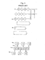
- such an electromagnetic induction type encoder which includes a number of scale coils 14,16 arrayed on a scale 10 along the measurement direction, and transmitting coils 24,26 and receiving coils 20, 22 disposed on a grid (may be referred to as a slider, too) 12 relatively movable in the measurement direction with respect to the scale 10, and is capable of detecting a relative movement amount of the scale 10 and the grid 12 from changes in magnetic fluxes detected by the receiving coils via the scale coils when the transmitting coils are magnetized.
- reference numeral 28 denotes a transmission control portion
- reference numeral 30 denotes a receiving control portion.
- the offset has been reduced by disposing the receiving coils 20 at a portion (that is, in the example of FIG. 2 , the middle part between both side transmitting coils) where the magnetic fields generated by the transmitting coils 24 are cancelled and is substantially brought to zero.
- the second receiving coils 22 are also disposed at both sides of the second transmitting coil 26 as shown in FIG. 3 , in addition to such a configuration composed of the first transmitting coils 24 in FIG. 2 and the first receiving coil 20 therein.
- the present invention was developed to solve such a problem in the prior art, and it is therefore an object of the invention to provide a highly accurate and inexpensive electromagnetic induction type encoder that is capable of obtaining strong signal intensity with offset reduced by a short scale coil, and is durable against fluctuations in the yaw direction.
- the present invention is featured in an electromagnetic induction type encoder including a number of scale coils arrayed on a scale along the measurement direction, transmitting coils and receiving coils that are disposed on a grid relatively movable in the measurement direction with respect to the scale, which encoder detects a relative movement amount of the scale and the grid from changes in magnetic fluxes detected by the receiving coils via the scale coil when the transmitting coils are magnetized; characterized in that only two sets of the transmitting coils, the receiving coils and the scale coils are disposed symmetrically with respect to the center of the scale, and scale coils of one set located at a symmetrical position around the center of the scale are disposed with 1/2 phase of the scale pitch shifted with respect to scale coils of the other set thereby solving the problem.
- the receiving coils can be connected to each other so as to acquire a difference in output between two receiving coils located at symmetrical positions around the center of the scale when causing an electric current to flow in the same direction as the transmitting coils.
- the receiving coils can be connected to each other so as to acquire the sum of output of two receiving coils located at symmetrical positions around the center of the scale when causing an electric current to flow in a different direction from the transmitting coils.
- the number of grid layers may be two.
- connection wiring of the scale coils may be omitted.
- the shapes of a plurality of sets of the transmitting coils and the receiving coils may be made common to each other.
- the shape of the scale coil may be made rectangular frame-like.
- the shape of the transmitting coils may be made rectangular.
- the shape of the receiving coils may be made rhomboid.
- the transmitting coils may be disposed so as to surround the receiving coils.
- the encoder is durable against fluctuations in the yaw direction.
- the grid can be made inexpensive by reducing the number of layers of the grid substrates.
- connection wiring 18 of the scale coil which is required in the art of Patent Document 2, is no longer required, an inexpensive scale can be provided by lightening the design rule.
- the wiring area on the grid can be reduced, wherein a small-sized encoder can be provided.
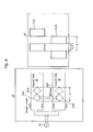
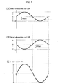
- Embodiment 1 of the present invention is such that transmitting coils 24A, 24B and the receiving coils 20A, 20B on the same grid 12 and scale coils 14A, 14B on the scale 10 are disposed by two sets each symmetrically with respect to the center of the scale 10, and scale coil 14A of one set is shifted by 1/2 phase of the scale pitch ( ⁇ ) with respect to scale coil 14B of the other set.
- the shapes of two sets of transmitting coils 24A, 24B and the receiving coils 20A, 20B are made common to each other, and are connected so that an electric current flows to the transmitting coils 24A, 24B in the same direction and a difference in signals of the receiving coils 20A, 20B is output.
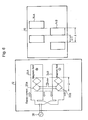
- Embodiment 2 of the present invention a description is given of Embodiment 2 of the present invention.
- the present embodiment is such that, as shown in FIGS. 6 , an electric current flows to the transmitting coils 24A, 24B in the reverse direction, and the transmitting coils 24A, 24B and the receiving coils 20A, 20B are connected so as to output the sum of signals of the receiving coils 20A, 20B.
- the shapes of the receiving coils are made rhomboid, the shapes thereof are not limited thereto.
- the shape may be sinusoidal or a shape similar thereto.
- the scale coil is made rectangular frame-like
- the shape of the scale coil is not limited to a rectangular frame.
- it may be shaped so as to be like a plate in which polarities are provided in a rectangle.
- the invention can be applied not only to inexpensive encoders but also general electromagnetic induction type encoders.
Landscapes
- Physics & Mathematics (AREA)
- General Physics & Mathematics (AREA)
- Transmission And Conversion Of Sensor Element Output (AREA)
Claims (10)
- Codeur de type à induction électromagnétique comportant:plusieurs bobines d'échelle disposées sur une échelle dans le sens du mesurage ;des bobines de transmission et des bobines de réception disposées sur un curseur relativement déplaçable dans le sens de mesurage par rapport à l'échelle,ce codeur détectant un degré de mouvement relatif de l'échelle et du curseur à partir des changements des flux magnétiques détectés par les bobines de réception par l'intermédiaire de la bobine d'échelle lorsque les bobines de transmission sont aimantées;caractérisé en ce que seulement deux ensembles de bobines de transmission (24A, 24B), de bobines de réception (20A, 20B) et de bobines d'échelle (14A, 14B) sont disposés symétriquement par rapport au centre de l'échelle (10), etles bobines d'échelle d'un ensemble (14A) situé symétriquement par rapport au centre de l'échelle (10) sont disposées alors que la moitié de la phase du pas de l'échelle (λ) est décalée par rapport aux bobines d'échelle de l'autre ensemble (14B).
- Codeur de type à induction électromagnétique selon la revendication 1, caractérisé en ce que les bobines de réception (20A, 20B) sont connectées l'une à l'autre de manière à fournir la différence entre les sorties des deux bobines de réception qui sont situées dans un emplacement symétrique par rapport au centre de l'échelle (10)) lorsqu'elles font circuler un courant électrique vers les bobines de transmission (24A, 24B) dans le même sens.
- Codeur de type à induction électromagnétique selon la revendication 1, caractérisé en ce que les bobines de réception (20A, 20B) sont connectées l'une à l'autre de manière à fournir la somme des sorties des deux bobines de réception qui sont situées dans un emplacement symétrique par rapport au centre de l'échelle (10) lorsqu'elles font circuler un courant électrique vers les bobines de transmission (24A, 24B) dans un sens différent.
- Codeur de type à induction électromagnétique selon l'une quelconque des revendications précédentes, caractérisé en ce que le nombre de couches du curseur est égal à deux.
- Codeur de type à induction électromagnétique selon l'une quelconque des revendications précédentes, caractérisé en ce que les fils de connexion de la bobine d'échelle (14A, 14B) sont omis.
- Codeur de type à induction électromagnétique selon l'une quelconque des revendications précédentes, caractérisé en ce que les deux ensembles de bobines de transmission (24A, 24B) et de bobines de réception (20A, 20B) sont mis à la même forme.
- Codeur de type à induction électromagnétique selon l'une quelconque des revendications précédentes, caractérisé en ce que les bobines d'échelle (14A, 14B) sont mises en forme rectangulaire semblable à un cadre.
- Codeur de type à induction électromagnétique selon l'une quelconque des revendications précédentes, caractérisé en ce que les bobines de transmission (24A, 24B) sont mises en forme rectangulaire.
- Codeur de type à induction électromagnétique selon l'une quelconque des revendications précédentes, caractérisé en ce que les bobines de réception (20A, 20B) sont mises en forme de rhomboïde.
- Codeur de type à induction électromagnétique selon l'une quelconque des revendications précédentes, caractérisé en ce que les bobines de transmission (24A, 24B) sont disposées de manière à entourer les bobines de réception (20A, 20B).
Applications Claiming Priority (1)
| Application Number | Priority Date | Filing Date | Title |
|---|---|---|---|
| JP2008023507A JP5224838B2 (ja) | 2008-02-04 | 2008-02-04 | 電磁誘導式エンコーダ |
Publications (2)
| Publication Number | Publication Date |
|---|---|
| EP2085751A1 EP2085751A1 (fr) | 2009-08-05 |
| EP2085751B1 true EP2085751B1 (fr) | 2015-09-16 |
Family
ID=40679487
Family Applications (1)
| Application Number | Title | Priority Date | Filing Date |
|---|---|---|---|
| EP09151984.3A Active EP2085751B1 (fr) | 2008-02-04 | 2009-02-03 | Codeur de type à induction électromagnétique |
Country Status (4)
| Country | Link |
|---|---|
| US (1) | US7906958B2 (fr) |
| EP (1) | EP2085751B1 (fr) |
| JP (1) | JP5224838B2 (fr) |
| CN (1) | CN101504293B (fr) |
Families Citing this family (33)
| Publication number | Priority date | Publication date | Assignee | Title |
|---|---|---|---|---|
| JP5885382B2 (ja) * | 2010-04-19 | 2016-03-15 | 株式会社ミツトヨ | 電磁誘導式直線型エンコーダ |
| JP5798397B2 (ja) | 2011-07-22 | 2015-10-21 | 株式会社ミツトヨ | 電磁誘導式絶対位置測定用エンコーダ |
| JP5809479B2 (ja) | 2011-08-03 | 2015-11-11 | 株式会社ミツトヨ | 電磁誘導式絶対位置測定用エンコーダ |
| JP5948620B2 (ja) * | 2011-09-16 | 2016-07-06 | 株式会社ミツトヨ | 誘導検出型ロータリエンコーダ |
| US9163926B2 (en) * | 2012-01-25 | 2015-10-20 | Mitutoyo Corporation | Inductive detection type rotary encoder |
| KR101491507B1 (ko) | 2014-01-20 | 2015-02-09 | 한국오므론전장 주식회사 | 자계 유도 보상 패턴이 구비되는 유도형 위치 센서 |
| JP6021136B1 (ja) * | 2016-02-03 | 2016-11-09 | 三菱重工工作機械株式会社 | 電磁誘導式位置検出器 |
| US9778072B1 (en) * | 2016-03-15 | 2017-10-03 | Mitutoyo Corporation | Absolute electromagnetic position encoder |
| JP6234497B2 (ja) | 2016-03-15 | 2017-11-22 | Thk株式会社 | エンコーダ装置及びエンコーダ装置付き運動案内装置 |
| US9835473B2 (en) | 2016-03-15 | 2017-12-05 | Mitutoyo Corporation | Absolute electromagnetic position encoder |
| US10520335B2 (en) * | 2016-08-24 | 2019-12-31 | Mitutoyo Corporation | Winding configuration for inductive position encoder |
| US10612943B2 (en) * | 2016-08-24 | 2020-04-07 | Mitutoyo Corporation | Winding and scale configuration for inductive position encoder |
| US10775199B2 (en) | 2016-08-24 | 2020-09-15 | Mitutoyo Corporation | Winding and scale configuration for inductive position encoder |
| CN108571985A (zh) * | 2017-03-07 | 2018-09-25 | 赛卓电子科技(上海)有限公司 | 电磁感应式旋转编码器 |
| JP7118627B2 (ja) * | 2017-12-01 | 2022-08-16 | 株式会社ミツトヨ | 電磁誘導式位置検出装置 |
| JP7154990B2 (ja) * | 2017-12-21 | 2022-10-18 | 株式会社ミツトヨ | 電磁誘導式エンコーダの巻線及びスケール構成 |
| JP2019113542A (ja) | 2017-12-21 | 2019-07-11 | 株式会社ミツトヨ | 電磁誘導式エンコーダの巻線及びスケール構成 |
| US10591316B2 (en) | 2018-03-30 | 2020-03-17 | Mitutoyo Corporation | Transmitter and receiver configuration for inductive position encoder |
| US10551217B2 (en) | 2018-06-29 | 2020-02-04 | Mitutoyo Corporation | Receiver line spacing in inductive position encoder |
| CN110487162B (zh) * | 2019-09-29 | 2020-09-08 | 桂林广陆数字测控有限公司 | 混合定位电磁感应式位移传感器 |
| JP7431032B2 (ja) | 2019-12-23 | 2024-02-14 | 株式会社ミツトヨ | 電磁誘導式エンコーダ |
| US11169008B2 (en) | 2020-03-23 | 2021-11-09 | Mitutoyo Corporation | Transmitter and receiver configuration for inductive position encoder |
| DE102021106510A1 (de) | 2020-03-23 | 2021-09-23 | Mitutoyo Corporation | Sender- und empfängerkonfiguration für induktionspositionsgeber |
| US11067414B1 (en) | 2020-03-23 | 2021-07-20 | Mitutoyo Corporation | Transmitter and receiver configuration for inductive position encoder |
| US11181395B2 (en) | 2020-03-23 | 2021-11-23 | Mitutoyo Corporation | Transmitter and receiver configuration for inductive position encoder |
| EP3961158B1 (fr) * | 2020-08-25 | 2022-11-23 | Dr. Johannes Heidenhain GmbH | Unité de balayage et dispositif inductif de mesure de position pourvu d'une telle unité de balayage |
| US11713983B2 (en) | 2021-06-30 | 2023-08-01 | Mitutoyo Corporation | Sensing winding configuration for inductive position encoder |
| US12072213B2 (en) | 2022-08-31 | 2024-08-27 | Mitutoyo Corporation | Inductive position encoder utilizing slanted scale pattern |
| US12072212B2 (en) | 2022-08-31 | 2024-08-27 | Mitutoyo Corporation | Inductive position encoder utilizing transmissive configuration |
| US12385764B2 (en) | 2022-12-30 | 2025-08-12 | Mitutoyo Corporation | Absolute position encoder utilizing single track configuration |
| US12546628B2 (en) | 2023-10-30 | 2026-02-10 | Mitutoyo Corporation | Inductive encoder with shield structures |
| US12553746B2 (en) | 2023-12-20 | 2026-02-17 | Mitutoyo Corporation | Measuring instrument with linear encoder tracks and arc motion |
| US12553747B2 (en) | 2023-12-20 | 2026-02-17 | Mitutoyo Corporation | Measuring instrument with arc encoder tracks |
Family Cites Families (8)
| Publication number | Priority date | Publication date | Assignee | Title |
|---|---|---|---|---|
| EP0337939B1 (fr) | 1988-03-28 | 1992-05-13 | C.A. Weidmüller GmbH & Co. | Capteur inductif et appareil de mesure pour obtenir la position relative d'un capteur |
| CN1085332C (zh) * | 1994-05-14 | 2002-05-22 | 辛纳普蒂克斯(英国)有限公司 | 位置编码器 |
| US6005387A (en) * | 1997-04-16 | 1999-12-21 | Mitutoyo Corporation | Reduced offset high accuracy induced current position transducer |
| JP2001201363A (ja) * | 2000-01-19 | 2001-07-27 | Omron Corp | 変位センサ |
| JP3504904B2 (ja) * | 2000-03-13 | 2004-03-08 | 株式会社ミツトヨ | 誘導型トランスデューサ及び電子ノギス |
| JP3842099B2 (ja) | 2001-10-12 | 2006-11-08 | 株式会社ミツトヨ | 磁気式エンコーダ |
| JP2005291929A (ja) * | 2004-03-31 | 2005-10-20 | Mitsutoyo Corp | 電磁誘導式エンコーダ |
| JP4615955B2 (ja) * | 2004-10-12 | 2011-01-19 | 株式会社ミツトヨ | 誘導型変位検出装置 |
-
2008
- 2008-02-04 JP JP2008023507A patent/JP5224838B2/ja active Active
-
2009
- 2009-02-02 US US12/320,695 patent/US7906958B2/en active Active
- 2009-02-03 EP EP09151984.3A patent/EP2085751B1/fr active Active
- 2009-02-04 CN CN2009100099872A patent/CN101504293B/zh active Active
Also Published As
| Publication number | Publication date |
|---|---|
| US20090195241A1 (en) | 2009-08-06 |
| EP2085751A1 (fr) | 2009-08-05 |
| JP5224838B2 (ja) | 2013-07-03 |
| CN101504293A (zh) | 2009-08-12 |
| JP2009186200A (ja) | 2009-08-20 |
| US7906958B2 (en) | 2011-03-15 |
| CN101504293B (zh) | 2012-06-06 |
Similar Documents
| Publication | Publication Date | Title |
|---|---|---|
| EP2085751B1 (fr) | Codeur de type à induction électromagnétique | |
| JP5885382B2 (ja) | 電磁誘導式直線型エンコーダ | |
| EP2549239B1 (fr) | Codeur de mesure de position absolu de type à induction électromagnétique | |
| JP5809479B2 (ja) | 電磁誘導式絶対位置測定用エンコーダ | |
| US6329813B1 (en) | Reduced offset high accuracy induced current absolute position transducer | |
| JP4615955B2 (ja) | 誘導型変位検出装置 | |
| US4612502A (en) | Magnetic length or angle measuring system having improved magnetic sensor arrangement | |
| EP1174687A2 (fr) | Capteur de position inductif | |
| EP1014041B1 (fr) | Capteur de position inductif à haute précision et décalage réduit | |
| JP5224830B2 (ja) | 電磁誘導式エンコーダ | |
| JP2020056754A (ja) | 電磁誘導式エンコーダ | |
| JP5676223B2 (ja) | 電磁誘導式エンコーダ | |
| JP2005077150A (ja) | 誘導型位置検出装置 | |
| JP5042891B2 (ja) | センサヘッド、及び誘導型変位検出装置 | |
| JP6134964B2 (ja) | 誘導型変位検出装置 | |
| US20200240812A1 (en) | Electromagnetic induction type encoder | |
| JP2007192722A (ja) | 位置検出装置 | |
| JP2002031546A (ja) | 磁気式エンコーダ | |
| CN113091778B (zh) | 电磁感应型编码器及其使用方法 | |
| JP2011043338A (ja) | 電流センサ | |
| JP4989919B2 (ja) | 誘導型位置検出装置 | |
| JP4112382B2 (ja) | 磁気式エンコーダの検出ヘッド及び磁気式エンコーダ |
Legal Events
| Date | Code | Title | Description |
|---|---|---|---|
| PUAI | Public reference made under article 153(3) epc to a published international application that has entered the european phase |
Free format text: ORIGINAL CODE: 0009012 |
|
| AK | Designated contracting states |
Kind code of ref document: A1 Designated state(s): AT BE BG CH CY CZ DE DK EE ES FI FR GB GR HR HU IE IS IT LI LT LU LV MC MK MT NL NO PL PT RO SE SI SK TR |
|
| AX | Request for extension of the european patent |
Extension state: AL BA RS |
|
| 17P | Request for examination filed |
Effective date: 20090821 |
|
| AKX | Designation fees paid |
Designated state(s): DE FR GB |
|
| 17Q | First examination report despatched |
Effective date: 20140730 |
|
| GRAP | Despatch of communication of intention to grant a patent |
Free format text: ORIGINAL CODE: EPIDOSNIGR1 |
|
| INTG | Intention to grant announced |
Effective date: 20150612 |
|
| GRAS | Grant fee paid |
Free format text: ORIGINAL CODE: EPIDOSNIGR3 |
|
| GRAA | (expected) grant |
Free format text: ORIGINAL CODE: 0009210 |
|
| AK | Designated contracting states |
Kind code of ref document: B1 Designated state(s): DE FR GB |
|
| REG | Reference to a national code |
Ref country code: GB Ref legal event code: FG4D |
|
| REG | Reference to a national code |
Ref country code: DE Ref legal event code: R096 Ref document number: 602009033628 Country of ref document: DE |
|
| REG | Reference to a national code |
Ref country code: FR Ref legal event code: PLFP Year of fee payment: 8 |
|
| REG | Reference to a national code |
Ref country code: DE Ref legal event code: R097 Ref document number: 602009033628 Country of ref document: DE |
|
| PLBE | No opposition filed within time limit |
Free format text: ORIGINAL CODE: 0009261 |
|
| STAA | Information on the status of an ep patent application or granted ep patent |
Free format text: STATUS: NO OPPOSITION FILED WITHIN TIME LIMIT |
|
| 26N | No opposition filed |
Effective date: 20160617 |
|
| REG | Reference to a national code |
Ref country code: FR Ref legal event code: PLFP Year of fee payment: 9 |
|
| REG | Reference to a national code |
Ref country code: FR Ref legal event code: PLFP Year of fee payment: 10 |
|
| PGFP | Annual fee paid to national office [announced via postgrant information from national office to epo] |
Ref country code: GB Payment date: 20260219 Year of fee payment: 18 |
|
| PGFP | Annual fee paid to national office [announced via postgrant information from national office to epo] |
Ref country code: DE Payment date: 20260218 Year of fee payment: 18 |
|
| PGFP | Annual fee paid to national office [announced via postgrant information from national office to epo] |
Ref country code: FR Payment date: 20260218 Year of fee payment: 18 |