EP2085848A1 - Dispositif de traitement et procédé de traitement destinés au traitement d'objets à l'aide d'une mesure temporelle - Google Patents
Dispositif de traitement et procédé de traitement destinés au traitement d'objets à l'aide d'une mesure temporelle Download PDFInfo
- Publication number
- EP2085848A1 EP2085848A1 EP08001825A EP08001825A EP2085848A1 EP 2085848 A1 EP2085848 A1 EP 2085848A1 EP 08001825 A EP08001825 A EP 08001825A EP 08001825 A EP08001825 A EP 08001825A EP 2085848 A1 EP2085848 A1 EP 2085848A1
- Authority
- EP
- European Patent Office
- Prior art keywords
- time
- machine
- control unit
- processing
- unit
- Prior art date
- Legal status (The legal status is an assumption and is not a legal conclusion. Google has not performed a legal analysis and makes no representation as to the accuracy of the status listed.)
- Granted
Links
Images

Classifications
-
- G—PHYSICS
- G05—CONTROLLING; REGULATING
- G05B—CONTROL OR REGULATING SYSTEMS IN GENERAL; FUNCTIONAL ELEMENTS OF SUCH SYSTEMS; MONITORING OR TESTING ARRANGEMENTS FOR SUCH SYSTEMS OR ELEMENTS
- G05B19/00—Program-control systems
- G05B19/02—Program-control systems electric
- G05B19/418—Total factory control, i.e. centrally controlling a plurality of machines, e.g. direct or distributed numerical control [DNC], flexible manufacturing systems [FMS], integrated manufacturing systems [IMS] or computer integrated manufacturing [CIM]
- G05B19/41815—Total factory control, i.e. centrally controlling a plurality of machines, e.g. direct or distributed numerical control [DNC], flexible manufacturing systems [FMS], integrated manufacturing systems [IMS] or computer integrated manufacturing [CIM] characterised by the cooperation between machine tools, manipulators and conveyor or other workpiece supply system, workcell
-
- G—PHYSICS
- G05—CONTROLLING; REGULATING
- G05B—CONTROL OR REGULATING SYSTEMS IN GENERAL; FUNCTIONAL ELEMENTS OF SUCH SYSTEMS; MONITORING OR TESTING ARRANGEMENTS FOR SUCH SYSTEMS OR ELEMENTS
- G05B19/00—Program-control systems
- G05B19/02—Program-control systems electric
- G05B19/04—Program control other than numerical control, i.e. in sequence controllers or logic controllers
- G05B19/042—Program control other than numerical control, i.e. in sequence controllers or logic controllers using digital processors
- G05B19/0421—Multiprocessor system
-
- G—PHYSICS
- G05—CONTROLLING; REGULATING
- G05B—CONTROL OR REGULATING SYSTEMS IN GENERAL; FUNCTIONAL ELEMENTS OF SUCH SYSTEMS; MONITORING OR TESTING ARRANGEMENTS FOR SUCH SYSTEMS OR ELEMENTS
- G05B2219/00—Program-control systems
- G05B2219/20—Pc systems
- G05B2219/25—Pc structure of the system
- G05B2219/25049—Leader processor gives timing information to followers
-
- G—PHYSICS
- G05—CONTROLLING; REGULATING
- G05B—CONTROL OR REGULATING SYSTEMS IN GENERAL; FUNCTIONAL ELEMENTS OF SUCH SYSTEMS; MONITORING OR TESTING ARRANGEMENTS FOR SUCH SYSTEMS OR ELEMENTS
- G05B2219/00—Program-control systems
- G05B2219/30—Nc systems
- G05B2219/33—Director till display
- G05B2219/33097—Variable ticks, align clocks, to synchronise cycles with other machine, robot
-
- G—PHYSICS
- G05—CONTROLLING; REGULATING
- G05B—CONTROL OR REGULATING SYSTEMS IN GENERAL; FUNCTIONAL ELEMENTS OF SUCH SYSTEMS; MONITORING OR TESTING ARRANGEMENTS FOR SUCH SYSTEMS OR ELEMENTS
- G05B2219/00—Program-control systems
- G05B2219/30—Nc systems
- G05B2219/34—Director, elements to supervisory
- G05B2219/34413—Add time stamp to command message
-
- G—PHYSICS
- G05—CONTROLLING; REGULATING
- G05B—CONTROL OR REGULATING SYSTEMS IN GENERAL; FUNCTIONAL ELEMENTS OF SUCH SYSTEMS; MONITORING OR TESTING ARRANGEMENTS FOR SUCH SYSTEMS OR ELEMENTS
- G05B2219/00—Program-control systems
- G05B2219/30—Nc systems
- G05B2219/45—Nc applications
- G05B2219/45051—Transfer line
-
- G—PHYSICS
- G05—CONTROLLING; REGULATING
- G05B—CONTROL OR REGULATING SYSTEMS IN GENERAL; FUNCTIONAL ELEMENTS OF SUCH SYSTEMS; MONITORING OR TESTING ARRANGEMENTS FOR SUCH SYSTEMS OR ELEMENTS
- G05B2219/00—Program-control systems
- G05B2219/30—Nc systems
- G05B2219/45—Nc applications
- G05B2219/45229—Woodworking
-
- G—PHYSICS
- G05—CONTROLLING; REGULATING
- G05B—CONTROL OR REGULATING SYSTEMS IN GENERAL; FUNCTIONAL ELEMENTS OF SUCH SYSTEMS; MONITORING OR TESTING ARRANGEMENTS FOR SUCH SYSTEMS OR ELEMENTS
- G05B2219/00—Program-control systems
- G05B2219/30—Nc systems
- G05B2219/45—Nc applications
- G05B2219/45234—Thin flat workpiece, sheet metal machining
-
- Y—GENERAL TAGGING OF NEW TECHNOLOGICAL DEVELOPMENTS; GENERAL TAGGING OF CROSS-SECTIONAL TECHNOLOGIES SPANNING OVER SEVERAL SECTIONS OF THE IPC; TECHNICAL SUBJECTS COVERED BY FORMER USPC CROSS-REFERENCE ART COLLECTIONS [XRACs] AND DIGESTS
- Y02—TECHNOLOGIES OR APPLICATIONS FOR MITIGATION OR ADAPTATION AGAINST CLIMATE CHANGE
- Y02P—CLIMATE CHANGE MITIGATION TECHNOLOGIES IN THE PRODUCTION OR PROCESSING OF GOODS
- Y02P90/00—Enabling technologies with a potential contribution to greenhouse gas [GHG] emissions mitigation
- Y02P90/02—Total factory control, e.g. smart factories, flexible manufacturing systems [FMS] or integrated manufacturing systems [IMS]
Definitions
- the present invention relates to a processing device and a processing method for processing moving objects, and more particularly to a processing device and a processing method for continuous measurement and processing of moving objects in a continuous machine by means of travel / time measurement in distributed systems.
- workpieces such as rigid plate material, such as solid wood or chipboard, so-called blockboard, plywood, composite panels made of wood, plastic or metal or the like detected on a conveyor and then performed a processing on the same.
- rigid plate material such as solid wood or chipboard, so-called blockboard, plywood, composite panels made of wood, plastic or metal or the like
- machining operation on the objects can be carried out in such a continuous machining, but various machining operations are possible, such as cutting, milling, grinding, drilling, etc. Further, it is also possible other parts on the objects, such as Workpieces, apply or stick or unscrew.
- the workpiece in an automated sequence of workpiece machining, can be guided to a plurality of processing stations by means of a conveyor with belt or chain conveyor without people having to intervene in the workflow.
- pass-through machines are equipped with a workpiece detection system and a position measuring system whose signals are fed to a control unit for processing.
- a workpiece In the inlet region of the conveyor, a workpiece can be detected, and a corresponding signal can be output.
- the approximate speed of the conveyor belt or transport chain e.g. can be determined by measuring the distance traveled at different times, thereby the approximate position of the workpiece in the continuous machine can be determined.
- a sensor By positioning sensors on the conveyor can thus be issued a signal that indicates that the arrival of a workpiece or object is measured at a sensor, which corresponds to the position of the workpiece. Then, a downstream actuator can be commanded to switch or move, so that after a certain distance covered the workpiece by the sensor this is processed by the actuator.
- a sensor therefore signals, eg by a trigger signal, that it has measured and an actuator is commanded, eg by a trigger signal, that it should switch or move.
- Disturbing influences are, for example, the reaction of the control, the slippage during feed of the workpiece, tolerances in the feed transport and in the workpiece detection, which can only be detected within certain precision limits.
- the processing device comprises a control unit with a timer for outputting a system time and at least two machine units connected to the control unit configured to receive the system time
- the first machine unit comprises at least one sensor element and is designed for Detecting an event and outputting an event time based on the system time related to the detection of the event
- the second machine unit comprises at least one actuator element, and configured to perform an operation according to a machining time predetermined by the control unit based on System time and event time.
- an exact position of an object in time can be accurately detected and communicated to other machine units via at least one control.
- This allows a much more accurate detection of an object and a significant more accurate control of machine units with actuator elements for processing objects, and saved by simply working in the time domain signal transformations.
- the precision in such a system does not depend on the running time of the communication lines and field buses between the components or the cycle time of the control, but only on the resolution of the system time, that is, the synchronization accuracy of the machine units with each other.
- a processing device in the sense of the invention is any system that has distributed times, and where the time of occurrence of an event, such as the detection of an object, can be sent from one unit to another, and then processed as a processing time after an event time can indicate the execution of an operation.
- the processing device is particularly suitable for a pass-through machine, but does not necessarily have to be a part of a pass-through machine, since cases are conceivable in which a first object is detected, but a Operation is performed on a second object, which need not be together with the first object on a conveyor.
- the first machine unit is designed to output the event with the system time based on the event time as a detection signal to the control unit.
- the control unit of the processing device is informed of the event time based on the system time and may instruct other machine units with the same system time to perform an operation.
- the control unit calculates the processing time based on the event time, wherein preferably the calculated processing time is output as a processing signal to the second machine unit. Therefore, a control unit does not have to output an accurate trigger signal to the second machine unit at a certain processing time, but it is sufficient to calculate a processing time before the processing time and inform the second machine unit beforehand so that the second machine unit itself starts operating at the predetermined time , This allows a more accurate control of the actuator element of the second machine unit.
- the processing device comprises a third machine unit with a second sensor element and a fourth machine unit with a second actuator element, wherein the third and fourth machine units are designed to receive the system time from the control unit, and the control unit is designed based on the Event and the event time to select the machine unit with actuator element to which the processing time is to be notified. Since the machine units with actuator element inform only about the processing time and are not triggered by the control unit at the time of processing, the processing time may be sent at an arbitrary time prior to the processing time so that bottlenecks do not arise on a communication line or field bus, and an accurate drive is ensured in the machine units due to the same time.
- the first and second machine units form a processing unit, which preferably comprises an aggregate control unit.
- the signal processing between the control unit and the unit control unit can be divided, whereby the control unit is relieved.
- the aggregate control unit is designed to communicate with the control unit via a bus system and to receive the system time via the bus system.
- the system time can be output from the control unit to an aggregate control unit, which also supplies the machine units connected thereto with the system time, so that without further communication lines to the control unit, the processing means can be extended by further machine units on the unit control unit.
- control unit synchronizes the machine units.
- a system time must be issued only once by a control unit, since this time can be synchronized in the individual machine units by a simple synchronization signal at later times.
- the first machine unit comprises a first memory for storing events and event times.
- a detected event and / or event time does not have to be immediately addressed to a Control unit can be passed, but can be cached in the machine unit, so that two or more events and / or event times can be sent together to a control unit.
- the second machine unit comprises a second memory for storing processing times.
- the system time corresponds to the real world time.
- real-world time it is possible to ensure that even two machine units far apart from each other, each receiving the world time, have the same time, one event time can be output to a larger network, and one processing time from a larger network, such as Internet, received and can be transferred.
- the processing device is contained in a continuous machine.
- the advantages described above can also be achieved in a continuous machine.
- the pass-through machine comprises an object sensor for detecting an object on a conveyor and for outputting an object detection signal including an object detection time based on the system time.
- an object sensor for detecting an object on a conveyor and for outputting an object detection signal including an object detection time based on the system time.
- the pass-through machine comprises a position sensor for outputting a measurement signal corresponding to a measurement of a position of a conveyor to the control unit, the measurement signal containing a measurement time based on the system time related to the measurement, and wherein the control unit is preferred is configured to calculate a position of an object on the conveyor at different times by using the measurement signal and the detection signal or the object detection signal.
- the control unit is preferred is configured to calculate a position of an object on the conveyor at different times by using the measurement signal and the detection signal or the object detection signal.
- a processing method includes outputting a defined system time from a controller having timers on at least two machine units, detecting an event with the first machine unit, outputting an event time based on the system time related to the detection of the event from the first machine unit to the control unit, and performing an operation according to a processing time predetermined by the control unit, based on the system time and the event time by the second machine unit.
- the method is suitable to be carried out in a continuous machine.
- a simple and reliable method for a precise position determination for objects in a continuous machine can be realized.
- a second machine unit may be designated to receive a command with a timing following the detection of the event to then perform any operation.
- the operation does not necessarily have to be performed on an object that triggered the event at the first machine unit. It is also conceivable that the triggering of this event is another object.
- a first object may trigger an event at an accurately detectable time, the event time, whereby the second machine unit receives a processing time to operate on, for example, a second machine unit.
- the time difference between the event time and the processing time only has to be chosen so large that a communication of the command for performing the operation can arrive at the second machine unit in time before the second machine unit is to perform an operation.
- the processing device may, but does not necessarily have to, be part of a conventional pass-through machine, since it is also suitable for other systems in which a first object is detected but an operation is performed on a second object that is not associated with the first object must lie on a conveyor.
- a pass-through machine may include a pass-through machine for processing plate-shaped workpieces, such as e.g. Solid wood or chipboard, so-called Tischlerplatten, plywood panels, composite panels of wood, plastic or metal or the like.
- a processing device for the pass-through machine comprises a control unit with a timer which generates a system time which is output on at least two machine units.
- the first and second machine units have the same system time, and the detection of an object from the first machine unit can be accurately defined by an event time based on the system time.
- the pass-through machine which transports objects at a constant speed, it can thus be deduced from the location of the first machine unit and the event time when the same object is located at the second machine unit.
- This time referred to below as the processing time, is calculated by the control unit, for example, and sent to the second machine unit so that it can process the object at the defined processing time.
- a position of the object can be accurately detected and transmitted without a control unit having to process trigger signals indicating that a sensor has just been measured, or an actuator should now shift or move.
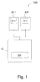
- Fig. 1 schematically shows a processing device 100.
- the processing device 100 includes a control unit C with a timer ZG, a first machine unit S11 with a sensor element SE11 and a second machine unit A11 with an actuator element AE11.
- control unit may be integrated in one of the machine units.
- Fig. 1 The machine units S11 and A11 are connected to the control unit C.
- the connection preferably takes place via a bus system, for example a field bus, wherein Profinet a standard for industrial Ethernet or a modification thereof can be used for the execution of the invention, for example.
- a wireless connection between the machine units and the control unit C is possible.
- the control unit C includes the timer ZG for outputting a system time.
- the control unit C is used to control the processing device 100 and can, for example, specify a processing time based on the system time given by the timer.
- the control unit C can be realized by a processor, computer or integrated circuit, such as an application specific integrated circuit (ASIC) or by software or an appropriate combination of the above.
- ASIC application specific integrated circuit
- the first machine unit S11 includes at least one sensor element SE11 and is configured to detect an event and output an event time based on the system time related to the detection of the event.
- the first machine unit is a sensor.
- the event may involve the detection of a leading edge or trailing edge of an object, for example a wooden panel.
- the first machine unit may store the event time, which is a time at the prevailing system time, and outputs an event time.
- the output event time does not have to be the event time itself, as it is also easy to output time or clock difference from a reference clock or reference time be measured. For example, a value of 5 clocks or 5 seconds after, for example, a last synchronization may be output, with the synchronization occurring at all units at the same time.
- the event may be output to the control unit C as the detection signal based on the system time-based event time.
- the detection signal then contains information about the event, where a simple indication such as yes / no is sufficient, that is, edge detected or not, and the event time, which as stated above, can be given either as an absolute time or as a difference time to a reference time , such as a synchronization process.
- the sensor element SE11 in the first machine unit S11 may be a commercially available sensor element that is used in sensors in automation technology.
- an optical sensor element having a clocking of, for example, 5 kHz may be used, which is a limiting factor for the accuracy of the measurement.
- the second machine unit A11 comprises at least one actuator element AE11 and is designed to perform an operation according to a processing time predetermined by the control unit, based on the system time and the event time.
- the second machine unit A11 is an actuator, ie the converter-related counterpart to a sensor which performs an operation at a predetermined processing time.
- the operation may be, for example, machining in the sense of punching, punching, cutting, gluing, drilling, etc., but other operations, such as redirecting, dispensing or removing an object that is present at the processing time at the second machine unit, are also possible.
- the actuator element may be, for example, an element that can perform such and similar functions.
- the second machine unit A11 receives the processing time based on the system time and the event time, and compares the predetermined processing time with an actual time, the system time prevailing upon receiving the processing time, which is the same for all units in the processing apparatus 100 and waits until the specified processing time corresponds to the system time. Therefore, the processing time may also be an absolute time or a relative time, that is, a time difference measured by a reference time, as described with respect to the event time described above.
- control unit C is designed to calculate the processing time based on the event time.
- the control unit C includes a processor, computer or integrated circuit as described above, and may determine when an object detected at the first machine unit S11, for example, in a conveyorized conveyor machine using the conveyor speed the second machine unit arrives. This arrival time then corresponds to the processing time, namely the time at which an object can be processed by the second machine unit.
- the control unit C is designed to output the processing time as a processing signal to the second machine unit A11.
- the second machine unit When the processing time is reached, the second machine unit then executes one of the operations described above.
- the first machine unit S11 does not report that it has measured, as is conventionally the case, but when or what has measured when, and gives the exact time the measurement, which is understood by all units in the processing device, since all are on the same system time.
- the second machine unit A11 is not informed that it should now shift or move, but is informed when it should go where by the predetermined processing time, based on the system time, which is the same for all units of the processing device 100.
- control unit C can be designed to synchronize.
- the first machine unit S11 may include a first memory, not shown, for storing the events and event times. This can be advantageous in particular in the event that short objects with short distances between leading and trailing edges or short distances between two objects can be detected and buffered, so that not every recorded event or event time must be output immediately, but can be temporarily stored and then multiple events and / or their event times can be issued at once.
- the time until transmission of the event time to the control unit C plus a processing time in the control unit and a time for sending the calculated processing time to the second machine unit A11 is shorter than the time it takes the object to from the first machine unit S11 to the second machine unit A11, for example on a conveyor.
- the second machine unit A11 may also include a second memory, not shown, for storing processing times.
- a second memory not shown, for storing processing times.
- several processing times and / or their processing setpoints can be cached, which can then be processed as needed.
- three processing times and their setpoint values can be stored, so that when the system time reaches one of the processing times, an operation corresponding to the desired value is performed.
- the system time can be the real world time, which means that all units in the processing device 100 can be synchronized, for example, by a radio signal from an atomic clock, such as the atomic clock of the Physikalisch-Technische Bundesweg.
- the first and second machine units may constitute a processing unit. This means that only one bidirectional communication line between the processing unit and the control unit C would then be necessary.
- the processing unit may comprise an aggregate control unit, which will be described later with reference to FIG Fig. 3 will be described in more detail.
- FIG. 2 a flow chart is described, showing the steps of a processing method for example, a continuous machine according to another embodiment of the invention.
- This method can be used, for example, by the in Fig. 1 shown processing apparatus 100 are executed.
- a defined system time from a control unit C with timer ZG to at least two Machine units S11 and A11 output.
- the system time may be the real world time, always paying attention that the units of the system, namely the control unit and machine units, display the same time.
- the system time can be transmitted over a fixed communication line, such as a fieldbus, or wirelessly.
- an event is detected with the first machine unit S11. For example, as described above, an object located on a conveyor of a pass-through machine can be detected if, for example, its leading edge is detected.
- the time related to the detection of the event may be output as the event time based on the system time from the first machine unit S11 to the control unit C.
- This is not a simple trigger signal indicating that, for example, the leading edge of an object has been detected, but a signal indicating the exact time at which the leading edge was detected.
- control unit need not consider a transmission time in a communication line from the first machine unit to the control unit, such as the trigger signal, since the transmitted event time does not change despite possible delays through a communication line. It only needs to be ensured that the time that the event time to the control unit takes and from the control unit to the second machine unit is less than the time that the object needs from the first machine unit to the second machine unit.
- an operation according to a processing time given by the control unit C is based on the system time and the event time, performed by the second machine unit.
- the processing time based on the event time and the system time, is preferably calculated by the control unit.
- the processing time is output, for example, as a processing signal from the control unit C to the second machine unit.
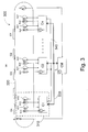
- pass machine 300 comprises a plurality of control units C1 to Cn, a plurality of machine units S11, S21 to Sn1; A11, A21 to An1; S12, S22 to Sn2; A12, A22 to An2, a main control unit CM, an object sensor S, a position sensor G, a conveyor 320, and a bus system 330, 340.
- Fig. 3 is the in Fig. 1 described processing device 100 represented by the machine units S11, A11 and the control unit C1, which in Fig. 3 is referred to as an aggregate control unit for distinguishing from the main control unit CM.
- Fig. 3 Functions of the control unit off Fig. 1 also taken over by the main control unit CM.
- the first and second machine units can also be understood as a processing unit 310, which preferably comprises the unit control unit C1.
- This aggregate control unit C1 and the main control unit CM can perform the functions of in Fig. 1 comply described control unit C.
- sensors and the machine units with actuator element can represent actuators, wherein the sensors and actuators are designed to measure, transmit or receive a time that can be processed directly in the sensors or actuators.
- the processing device may also include a third machine unit S12 with a second sensor element and a fourth machine unit with a second actuator element A12.
- the third and fourth machine units are also designed to receive the system time from the control unit or the main control unit CM by the aggregate control unit C1.
- the aggregate control unit C1 is further configured to select, based on the event and the event time, the engine unit with actuator element A11, A12 to be notified of the machining time.
- a sensor for example, machine unit S11
- an actuator for example, machine unit A11
- an event detected by machine unit S11 is notified to machine unit A11.
- the event is a detection of a leading edge of an object
- that information may be important to the second and fourth machine units, with the second machine unit, for example, drilling a hole in the object and drilling the hole in the fourth machine unit an adhesive is filled.
- the unit control units C1 to Cn shown are preferably designed to communicate with the main control unit CM via a bus system 330, 340 and to receive the system time via the bus system 330, 340.
- a system time is transmitted and preferably also a synchronization takes place via the communication line 340, which is also indicated by the arrow direction.
- a system time represented by the clock in the main control unit is transmitted to the unit control units C1 to Cn.
- a lightning bolt symbol illustrating that a synchronization process can synchronize the aggregate controllers C1 to Cn in phase synchronization.
- the second communication line 330 is bidirectional and sends signals from the unit control units C1 to Cn to the main control unit CM and from the main control unit to the unit control units. For example, the detection signals from the unit control units are sent to the main control unit, and the main control unit CM can send processing signals to the unit control units C1 to Cn.
- the two functions of the communication lines 330 and 340 may also be integrated into a single bus system.
- This can also be relative slow field buses and different control units are used, as described above, in the present invention does not depend on the exact reception or transmission of trigger signals, but signals are sent with a timing and received from / to the machine units. The exact position can thus be detected in time and transmitted over several field buses and different control units.
- the distributed system For example, at a location of the distributed system, e.g. in one of the aggregate control units or the main control unit for data from the position sensor G, the calculated data on the determination of the relative or absolute times and the corresponding paths, the processing times and Aktorsolllitis determined and sent again to different control units and / or the fieldbuses connected actuators.
- processing unit 310 will be described as an example of the unit control units C1 to Cn with their respective machine units.
- the machine units are connected to the control unit C, the aggregate control units C1 to Cn in Fig. 3 , and can communicate bidirectionally with each other.
- the system time is sent to all subordinate aggregate control units C1 to Cn and from there to the connected machine units.
- the processing unit 310 is therefore always kept at the same system time with the other units of the pass-through machine 300.
- the processing unit may include a plurality of machine units that may represent sensors and actuators.
- the continuous machine of Fig. 3 an object sensor S for detecting an object O1 to On on the conveyor 320 and for outputting an object detection signal including an object detection time based on the system time.
- This object detection time is communicated to the main control unit CM.
- the object sensor S functions similarly to the sensor element machine units described above, and thus can prepare the machine units and their aggregate control units for the arrival of an object.
- the objects O1 to On are moved by the conveyor as constant as possible.
- the speed may be in the range of 0.1 m / s to 20 m / s and preferably between 0.5 m / s and 3 m / s.
- the object sensor S registers in each case the positive and / or negative switching edge of an object and links this in the object sensor with the object detection time, similar to the machine units with sensor element.
- the pass-through machine may further include a position encoder G for outputting a measurement signal corresponding to a measurement of a position of the conveyor 320 to the main control unit CM, the measurement signal including a measurement time based on the system time related to the measurement.
- the position sensor G serves to measure the movement of the conveyor 320.
- the position sensor G can measure the progress or rotation of the conveyor 320 at several consecutive times, whereby the distance covered can be measured in a certain time.
- the position of the conveyor belt of the conveyor 320 is preferably determined cyclically in the shortest possible sampling times by the position sensor G and linked in conjunction with the time of measurement.
- This information of the object sensor S and the position sensor G can then be sent to the main control unit CM, where this information can be processed, for example, so that the speed of the conveyor can be determined, as well as a variation in speed, since the length of the path at the same Can distinguish time intervals.
- this information can be processed, for example, so that the speed of the conveyor can be determined, as well as a variation in speed, since the length of the path at the same Can distinguish time intervals.
- an approximately constant speed is assumed.
- the speed from the main control unit CM or the aggregate control units C1 to Cn can be used to calculate a position of an object on the conveyor at different times.
- the speed is derived from measurement signals from the position sensor G and with the aid of the event time or object detection time at which an object was at a certain position, the position of the object can be predicted in the future, which in turn is the processing time to the machine units can be passed with actuator element for editing.
- the main control unit CM links, by a special algorithm, the switching timings of the above-described switching edge to the now prevailing waypoint of the position sensor G.
- the results of the linking can be provided to the aggregate control units C1 to Cn.
- the control unit for example, the main control unit or the aggregate control unit or a combination thereof, then calculates the control tasks of the individual machine functions and thus determine the exact switching paths for the machine units with actuator element.
- the precision of the pass-through machine thus does not necessarily depend on the runtime of the fieldbuses or the cycle time of the respective control units, but on a change in the conveyor belt speed and the resolution of the system time in the machine units and the position sensor and object sensor, which can also receive the system time and synchronized , It only has to be ensured that the time between the detection of two objects and the processing time of, for example, the second machine unit is greater than the running time of the communication from the first machine unit for processing and back to the second machine unit.
- the wiring complexity compared to conventional continuous machines can be significantly reduced and a saving of redundant sensors, cross information between controllers and signal conversions is possible. Above all, however, the objects can be detected much more accurately and machine units with actuator element can be controlled much more accurately.
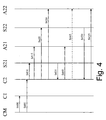
- main control unit CM transmits the system time in steps S400 and S405 to the aggregate control units C1 and C2.
- arrows for steps S400 and S405 are spaced apart, but this does not mean that there must be a time delay between these two steps. Therefore, it is also possible that the output of the system time or a synchronization of the system from all aggregate control units can be understood simultaneously.
- steps S410, S415, S420 and S430 the system time or synchronization is transmitted from the engine control unit C2 to the engine units S21, A21, S22 and A22. As with steps S400 and S405, this transmission may also occur simultaneously and is in Fig. 4 provided with intervals only for reasons of readability.
- the corresponding detection signal having the event time is sent back to the aggregate control unit C2, which in turn can calculate a machining time by itself, and can send it as a machining signal to the engine unit A21 in step S440.
- the main control unit CM calculates this processing time, the detection signal then having to be sent from the unit control unit C2 back to the main control unit CM, calculated there, and sent back to the unit control unit C2.
- This alternative is in Fig. 4 not shown, however, is another way for a communication process.
- Step S445 is represented by a dashed arrow indicating that this step is optional.
- This step corresponds to the situation discussed above that an event at the machine unit S21 may also cause machining in another actuator-type machine unit, for example, machine unit A22, so that two different machine unit processing times based on the same event time and system time of the machine unit Aggregate control unit or main control unit can be calculated.
- step S450 it is shown that in a further advance of the object 03, the machine unit S22 can detect the object 03 and can output a corresponding event time back to the unit control unit C2. This event time may in turn be used in the aggregate control unit C2 to calculate another processing time that may be sent to the machine unit A22 in step S455 so that the machine unit A22 performs an operation at the predetermined second processing time.
Landscapes
- Engineering & Computer Science (AREA)
- Physics & Mathematics (AREA)
- General Physics & Mathematics (AREA)
- Automation & Control Theory (AREA)
- General Engineering & Computer Science (AREA)
- Manufacturing & Machinery (AREA)
- Quality & Reliability (AREA)
- Numerical Control (AREA)
- Control Of Conveyors (AREA)
- Multi-Process Working Machines And Systems (AREA)
- Electric Clocks (AREA)
- Measurement Of Velocity Or Position Using Acoustic Or Ultrasonic Waves (AREA)
- Electrical Discharge Machining, Electrochemical Machining, And Combined Machining (AREA)
- Programmable Controllers (AREA)
- Time Recorders, Dirve Recorders, Access Control (AREA)
- Electromechanical Clocks (AREA)
- Air Bags (AREA)
- General Factory Administration (AREA)
- Geophysics And Detection Of Objects (AREA)
Priority Applications (8)
| Application Number | Priority Date | Filing Date | Title |
|---|---|---|---|
| ES08001825T ES2362048T3 (es) | 2008-01-31 | 2008-01-31 | Dispositivo de mecanizado y procedimiento de mecanizado para mecanizar objetos por medio de medición del tiempo. |
| PL08001825T PL2085848T3 (pl) | 2008-01-31 | 2008-01-31 | Zespół obróbczy i sposób obróbki obiektów poprzez pomiar czasu |
| DE502008002805T DE502008002805D1 (de) | 2008-01-31 | 2008-01-31 | Bearbeitungseinrichtung und Bearbeitungsverfahren zur Bearbeitung von Objekten mittels Zeitmessung |
| EP08001825A EP2085848B1 (fr) | 2008-01-31 | 2008-01-31 | Dispositif de traitement et procédé de traitement destinés au traitement d'objets à l'aide d'une mesure temporelle |
| DE502008001519T DE502008001519D1 (de) | 2008-01-31 | 2008-07-17 | Sensor mit Zeitglied zum Ausgeben einer Objekterfassungszeit |
| DK08104775.5T DK2085841T3 (da) | 2008-01-31 | 2008-07-17 | Sensor med tidsled til afgivelse af en objektregistreringstid |
| EP08104775A EP2085841B1 (fr) | 2008-01-31 | 2008-07-17 | Capteur avec horloge pour fournir le temps de détection d' un objet |
| AT08104775T ATE484780T1 (de) | 2008-01-31 | 2008-07-17 | Sensor mit zeitglied zum ausgeben einer objekterfassungszeit |
Applications Claiming Priority (1)
| Application Number | Priority Date | Filing Date | Title |
|---|---|---|---|
| EP08001825A EP2085848B1 (fr) | 2008-01-31 | 2008-01-31 | Dispositif de traitement et procédé de traitement destinés au traitement d'objets à l'aide d'une mesure temporelle |
Publications (2)
| Publication Number | Publication Date |
|---|---|
| EP2085848A1 true EP2085848A1 (fr) | 2009-08-05 |
| EP2085848B1 EP2085848B1 (fr) | 2011-03-09 |
Family
ID=39713952
Family Applications (2)
| Application Number | Title | Priority Date | Filing Date |
|---|---|---|---|
| EP08001825A Not-in-force EP2085848B1 (fr) | 2008-01-31 | 2008-01-31 | Dispositif de traitement et procédé de traitement destinés au traitement d'objets à l'aide d'une mesure temporelle |
| EP08104775A Active EP2085841B1 (fr) | 2008-01-31 | 2008-07-17 | Capteur avec horloge pour fournir le temps de détection d' un objet |
Family Applications After (1)
| Application Number | Title | Priority Date | Filing Date |
|---|---|---|---|
| EP08104775A Active EP2085841B1 (fr) | 2008-01-31 | 2008-07-17 | Capteur avec horloge pour fournir le temps de détection d' un objet |
Country Status (6)
| Country | Link |
|---|---|
| EP (2) | EP2085848B1 (fr) |
| AT (1) | ATE484780T1 (fr) |
| DE (2) | DE502008002805D1 (fr) |
| DK (1) | DK2085841T3 (fr) |
| ES (1) | ES2362048T3 (fr) |
| PL (1) | PL2085848T3 (fr) |
Families Citing this family (10)
| Publication number | Priority date | Publication date | Assignee | Title |
|---|---|---|---|---|
| EP2455830A1 (fr) | 2010-11-23 | 2012-05-23 | Siemens Aktiengesellschaft | Procédé destiné à la détection de modifications de signaux d'entrée |
| DE102012101909B3 (de) | 2012-03-07 | 2013-01-03 | Sick Ag | Entfernungsmessender Sensor und Verfahren zur Synchronisierung |
| DE202012100807U1 (de) | 2012-03-07 | 2013-06-11 | Sick Ag | Entfernungsmessender Sensor |
| US9102493B2 (en) * | 2012-10-02 | 2015-08-11 | Lamus Enterprises Inc | Tape monitoring system |
| EP2940488B1 (fr) | 2014-04-30 | 2016-05-18 | Sick Ag | Appareil et procédé pour la détection par moyen optique d'un objet |
| DE202014102040U1 (de) | 2014-04-30 | 2015-07-31 | Sick Ag | Sensor |
| CN111983948A (zh) * | 2020-07-07 | 2020-11-24 | 宝能(广州)汽车研究院有限公司 | 多传感器数据同步方法及其设备 |
| DE102021125057A1 (de) | 2021-09-28 | 2023-03-30 | Turck Holding Gmbh | Vorrichtung und Verfahren zum Erfassen und Steuern eines Prozesses |
| EP4451073A1 (fr) * | 2023-04-18 | 2024-10-23 | Siemens Aktiengesellschaft | Système de traitement et procédé de traitement d'un produit a traiter transporté sur un dispositif de transport |
| CN116689205B (zh) * | 2023-08-07 | 2023-10-13 | 江苏瑞奥减速机械有限公司 | 一种多用途水流喷管减速器 |
Citations (4)
| Publication number | Priority date | Publication date | Assignee | Title |
|---|---|---|---|---|
| US5463296A (en) * | 1993-06-30 | 1995-10-31 | Allen-Bradley Company, Inc. | Motion controller with remote linking |
| US5887029A (en) | 1994-05-31 | 1999-03-23 | Allen-Bradley Company, Llc | Method of scheduling spatially separated control events with an industrial controller |
| WO1999014645A1 (fr) * | 1997-09-18 | 1999-03-25 | Homag Maschinenbau Ag | Procede et dispositif d'usinage en continu de pieces en forme de plaques |
| EP1659465A2 (fr) | 2004-11-23 | 2006-05-24 | Rockwell Automation Technologies, Inc. | Protocole de réseau à marquage temporel pour la synchronisation symétrique à cycle unique et l'utilisation de structures de données dynamiques |
Family Cites Families (5)
| Publication number | Priority date | Publication date | Assignee | Title |
|---|---|---|---|---|
| US5555504A (en) * | 1994-06-10 | 1996-09-10 | Johnson & Johnson Vision Products, Inc. | Production line tracking and quality control system |
| US6173207B1 (en) * | 1997-09-22 | 2001-01-09 | Agilent Technologies, Inc. | Real-time control system with non-deterministic communication |
| US6236277B1 (en) * | 1999-09-30 | 2001-05-22 | Rockwell Technologies, Llc | Low deviation synchronization clock |
| DE102004050386B4 (de) * | 2004-10-15 | 2014-10-09 | Siemens Aktiengesellschaft | Verfahren zur Analyse eines technischen Prozesses |
| DE102005045855A1 (de) * | 2005-09-26 | 2007-03-29 | Siemens Ag | Verfahren und Vorrichtung zur Erleichterung der Einstellung von Systemen, bei welchen Objekten bewegt werden |
-
2008
- 2008-01-31 PL PL08001825T patent/PL2085848T3/pl unknown
- 2008-01-31 DE DE502008002805T patent/DE502008002805D1/de active Active
- 2008-01-31 ES ES08001825T patent/ES2362048T3/es active Active
- 2008-01-31 EP EP08001825A patent/EP2085848B1/fr not_active Not-in-force
- 2008-07-17 AT AT08104775T patent/ATE484780T1/de active
- 2008-07-17 EP EP08104775A patent/EP2085841B1/fr active Active
- 2008-07-17 DK DK08104775.5T patent/DK2085841T3/da active
- 2008-07-17 DE DE502008001519T patent/DE502008001519D1/de active Active
Patent Citations (4)
| Publication number | Priority date | Publication date | Assignee | Title |
|---|---|---|---|---|
| US5463296A (en) * | 1993-06-30 | 1995-10-31 | Allen-Bradley Company, Inc. | Motion controller with remote linking |
| US5887029A (en) | 1994-05-31 | 1999-03-23 | Allen-Bradley Company, Llc | Method of scheduling spatially separated control events with an industrial controller |
| WO1999014645A1 (fr) * | 1997-09-18 | 1999-03-25 | Homag Maschinenbau Ag | Procede et dispositif d'usinage en continu de pieces en forme de plaques |
| EP1659465A2 (fr) | 2004-11-23 | 2006-05-24 | Rockwell Automation Technologies, Inc. | Protocole de réseau à marquage temporel pour la synchronisation symétrique à cycle unique et l'utilisation de structures de données dynamiques |
Also Published As
| Publication number | Publication date |
|---|---|
| PL2085848T3 (pl) | 2011-09-30 |
| DE502008002805D1 (de) | 2011-04-21 |
| ATE484780T1 (de) | 2010-10-15 |
| EP2085841B1 (fr) | 2010-10-13 |
| EP2085841A1 (fr) | 2009-08-05 |
| EP2085848B1 (fr) | 2011-03-09 |
| ES2362048T3 (es) | 2011-06-27 |
| DE502008001519D1 (de) | 2010-11-25 |
| DK2085841T3 (da) | 2010-11-15 |
Similar Documents
| Publication | Publication Date | Title |
|---|---|---|
| EP2085848B1 (fr) | Dispositif de traitement et procédé de traitement destinés au traitement d'objets à l'aide d'une mesure temporelle | |
| EP1511680B1 (fr) | Dispositif servant a transporter et a traiter des articles individuels | |
| DE60012815T2 (de) | Numerisches Steuersystem | |
| DE102012022522B4 (de) | Motorsteuervorrichtung zur synchronen Steuerung einer Befehlsgeberachse und einer Befehlsempfängerachse | |
| DE19500822C1 (de) | Ultraschall-Kantenfühler zur Erfassung der Bahnkante einer Warenbahn | |
| DE102008008602B4 (de) | Transfervorrichtung für Werkstückträger sowie Verfahren zum Transportieren von Werkstückträgern | |
| EP1277028B1 (fr) | Instrument de mesure a coordonnees ou machine-outil | |
| DE3829734A1 (de) | Stellmotorsystem einer transportstrasse | |
| EP0917954B1 (fr) | Dispositif et procédé pour produire un valeur de référence d'une position individuelle dans un procédé d'impression | |
| DE2332664C2 (de) | Programmsteuerungssystem | |
| EP0965165B1 (fr) | Procede et dispositif pour maintenir le parfait synchronisme d'elements d'entrainement individuels en reseau d'un systeme d'entrainement decentralise | |
| EP3267272B1 (fr) | Procédé et dispositif de transmission de données | |
| EP3035000B1 (fr) | Dispositif et procede de verification d'un signal de travail d'un dispositif de mesure de position | |
| EP1311934B1 (fr) | Procede pour produire automatiquement plusieurs impulsions electriques, au moyen de valeurs numeriques par defaut, notamment en tant que simulation de capteur incrementiel | |
| DE4026413C2 (de) | Positionier-Steuervorrichtung | |
| DE112015006524B4 (de) | Numerische Steuerungseinrichtung | |
| EP0815500B1 (fr) | Dispositif permettant de tenir compte du temps de reaction d'un equipement commande en fonction du trajet de deplacement | |
| DE10208791C5 (de) | Druckmaschinenantriebssystem | |
| EP2455830A1 (fr) | Procédé destiné à la détection de modifications de signaux d'entrée | |
| WO2018130331A1 (fr) | Commande d'un processus technique avec une installation à plusieurs noyaux de calcul | |
| DE4327674C2 (de) | Einrichtung zum Erfassen vorzugsweise schnellaufender Eisenbahnräder | |
| DE102007020440B4 (de) | Synchronisationsbussystem, Kommunikationseinheiten für ein Synchronisationsbussystem und Verfahren zum Austauschen von Nachrichten zur zeitlichen Synchronisation | |
| EP0813704A1 (fr) | Procede de commande d'un systeme de production | |
| DE2415307B2 (de) | Einrichtung zur synchronisation der ausgaben von mehreren rechnern | |
| DE4327324B4 (de) | Verfahren zur Bestimmung eines Prozeßereignisses |
Legal Events
| Date | Code | Title | Description |
|---|---|---|---|
| PUAI | Public reference made under article 153(3) epc to a published international application that has entered the european phase |
Free format text: ORIGINAL CODE: 0009012 |
|
| AK | Designated contracting states |
Kind code of ref document: A1 Designated state(s): AT BE BG CH CY CZ DE DK EE ES FI FR GB GR HR HU IE IS IT LI LT LU LV MC MT NL NO PL PT RO SE SI SK TR |
|
| AX | Request for extension of the european patent |
Extension state: AL BA MK RS |
|
| 17P | Request for examination filed |
Effective date: 20100119 |
|
| 17Q | First examination report despatched |
Effective date: 20100317 |
|
| AKX | Designation fees paid |
Designated state(s): DE ES FR IT PL |
|
| GRAP | Despatch of communication of intention to grant a patent |
Free format text: ORIGINAL CODE: EPIDOSNIGR1 |
|
| GRAS | Grant fee paid |
Free format text: ORIGINAL CODE: EPIDOSNIGR3 |
|
| GRAA | (expected) grant |
Free format text: ORIGINAL CODE: 0009210 |
|
| AK | Designated contracting states |
Kind code of ref document: B1 Designated state(s): DE ES FR IT PL |
|
| REF | Corresponds to: |
Ref document number: 502008002805 Country of ref document: DE Date of ref document: 20110421 Kind code of ref document: P |
|
| REG | Reference to a national code |
Ref country code: DE Ref legal event code: R096 Ref document number: 502008002805 Country of ref document: DE Effective date: 20110421 |
|
| REG | Reference to a national code |
Ref country code: ES Ref legal event code: FG2A Ref document number: 2362048 Country of ref document: ES Kind code of ref document: T3 Effective date: 20110627 |
|
| REG | Reference to a national code |
Ref country code: PL Ref legal event code: T3 |
|
| PLBE | No opposition filed within time limit |
Free format text: ORIGINAL CODE: 0009261 |
|
| STAA | Information on the status of an ep patent application or granted ep patent |
Free format text: STATUS: NO OPPOSITION FILED WITHIN TIME LIMIT |
|
| 26N | No opposition filed |
Effective date: 20111212 |
|
| REG | Reference to a national code |
Ref country code: DE Ref legal event code: R097 Ref document number: 502008002805 Country of ref document: DE Effective date: 20111212 |
|
| REG | Reference to a national code |
Ref country code: FR Ref legal event code: ST Effective date: 20120928 |
|
| PG25 | Lapsed in a contracting state [announced via postgrant information from national office to epo] |
Ref country code: FR Free format text: LAPSE BECAUSE OF NON-PAYMENT OF DUE FEES Effective date: 20120131 |
|
| REG | Reference to a national code |
Ref country code: PL Ref legal event code: LAPE |
|
| PG25 | Lapsed in a contracting state [announced via postgrant information from national office to epo] |
Ref country code: PL Free format text: LAPSE BECAUSE OF NON-PAYMENT OF DUE FEES Effective date: 20120131 |
|
| PGFP | Annual fee paid to national office [announced via postgrant information from national office to epo] |
Ref country code: IE Payment date: 20190124 Year of fee payment: 14 |
|
| PGFP | Annual fee paid to national office [announced via postgrant information from national office to epo] |
Ref country code: IT Payment date: 20200127 Year of fee payment: 13 |
|
| REG | Reference to a national code |
Ref country code: ES Ref legal event code: FD2A Effective date: 20210607 |
|
| PG25 | Lapsed in a contracting state [announced via postgrant information from national office to epo] |
Ref country code: ES Free format text: LAPSE BECAUSE OF NON-PAYMENT OF DUE FEES Effective date: 20200201 |
|
| PG25 | Lapsed in a contracting state [announced via postgrant information from national office to epo] |
Ref country code: IT Free format text: LAPSE BECAUSE OF NON-PAYMENT OF DUE FEES Effective date: 20210131 |
|
| PGFP | Annual fee paid to national office [announced via postgrant information from national office to epo] |
Ref country code: DE Payment date: 20220615 Year of fee payment: 16 |
|
| P01 | Opt-out of the competence of the unified patent court (upc) registered |
Effective date: 20230529 |
|
| REG | Reference to a national code |
Ref country code: DE Ref legal event code: R119 Ref document number: 502008002805 Country of ref document: DE |
|
| PG25 | Lapsed in a contracting state [announced via postgrant information from national office to epo] |
Ref country code: DE Free format text: LAPSE BECAUSE OF NON-PAYMENT OF DUE FEES Effective date: 20240801 |
|
| PG25 | Lapsed in a contracting state [announced via postgrant information from national office to epo] |
Ref country code: DE Free format text: LAPSE BECAUSE OF NON-PAYMENT OF DUE FEES Effective date: 20240801 |