EP2087302B1 - Gehäuse für ein haushaltsgerät - Google Patents
Gehäuse für ein haushaltsgerät Download PDFInfo
- Publication number
- EP2087302B1 EP2087302B1 EP07822041A EP07822041A EP2087302B1 EP 2087302 B1 EP2087302 B1 EP 2087302B1 EP 07822041 A EP07822041 A EP 07822041A EP 07822041 A EP07822041 A EP 07822041A EP 2087302 B1 EP2087302 B1 EP 2087302B1
- Authority
- EP
- European Patent Office
- Prior art keywords
- cover
- lid
- domestic appliance
- appliance according
- detent
- Prior art date
- Legal status (The legal status is an assumption and is not a legal conclusion. Google has not performed a legal analysis and makes no representation as to the accuracy of the status listed.)
- Active
Links
- 210000002105 tongue Anatomy 0.000 description 3
- 230000000295 complement effect Effects 0.000 description 1
- 238000010276 construction Methods 0.000 description 1
- 238000006073 displacement reaction Methods 0.000 description 1
- 238000002347 injection Methods 0.000 description 1
- 239000007924 injection Substances 0.000 description 1
- 230000037431 insertion Effects 0.000 description 1
- 238000003780 insertion Methods 0.000 description 1
- 239000011810 insulating material Substances 0.000 description 1
- 239000012774 insulation material Substances 0.000 description 1
- 238000004519 manufacturing process Methods 0.000 description 1
- 230000035515 penetration Effects 0.000 description 1
- IHQKEDIOMGYHEB-UHFFFAOYSA-M sodium dimethylarsinate Chemical class [Na+].C[As](C)([O-])=O IHQKEDIOMGYHEB-UHFFFAOYSA-M 0.000 description 1
Images


Classifications
-
- F—MECHANICAL ENGINEERING; LIGHTING; HEATING; WEAPONS; BLASTING
- F25—REFRIGERATION OR COOLING; COMBINED HEATING AND REFRIGERATION SYSTEMS; HEAT PUMP SYSTEMS; MANUFACTURE OR STORAGE OF ICE; LIQUEFACTION SOLIDIFICATION OF GASES
- F25D—REFRIGERATORS; COLD ROOMS; ICE-BOXES; COOLING OR FREEZING APPARATUS NOT OTHERWISE PROVIDED FOR
- F25D23/00—General constructional features
- F25D23/06—Walls
- F25D23/065—Details
-
- F—MECHANICAL ENGINEERING; LIGHTING; HEATING; WEAPONS; BLASTING
- F24—HEATING; RANGES; VENTILATING
- F24C—DOMESTIC STOVES OR RANGES ; DETAILS OF DOMESTIC STOVES OR RANGES, OF GENERAL APPLICATION
- F24C15/00—Details
-
- F—MECHANICAL ENGINEERING; LIGHTING; HEATING; WEAPONS; BLASTING
- F25—REFRIGERATION OR COOLING; COMBINED HEATING AND REFRIGERATION SYSTEMS; HEAT PUMP SYSTEMS; MANUFACTURE OR STORAGE OF ICE; LIQUEFACTION SOLIDIFICATION OF GASES
- F25D—REFRIGERATORS; COLD ROOMS; ICE-BOXES; COOLING OR FREEZING APPARATUS NOT OTHERWISE PROVIDED FOR
- F25D2400/00—General features of, or devices for refrigerators, cold rooms, ice-boxes, or for cooling or freezing apparatus not covered by any other subclass
- F25D2400/18—Aesthetic features
Definitions
- the present invention relates to a household appliance having a housing which has a body and a lid, which can be fastened to an opening of the body by a first detent surface of the lid engages behind a second detent surface of the body.
- a home appliance in which further the lid has a projection is made DE 102004045475 known.
- Object of the present invention is therefore to provide the housing of the household appliance with a carcass and a lockable on the body lid, in spite of any inaccuracy or deformability of the lid and body secure locking of the lid and body is guaranteed.
- the problem is solved according to claim 1.
- the distance from the projection and recess of the locking surfaces can be made as small as necessary, so that manufacturing tolerances of this distance or deformability of lying between the projection and recess on the one hand and the locking surfaces on the other hand portion of the lid can not jeopardize the catch; the remaining area of the lid may be deformable or generously tolerated without affecting the safety of the latch.
- the body and lid have contours which are insertable into one another in a first orientation of the lid to the body and in the inserted state allow a pivoting movement of the lid in a second orientation, through which the locking surfaces lock together.
- the interlocking contours also define an axis of pivotal movement.
- the contour formed on the lid is a bulge
- the contour formed on the body is an undercut, in which the bulge is insertable.
- An axis for the pivotal movement of the lid can be easily defined by the engagement of the contours of the body and lid together.
- the two contours overlap in the direction parallel to the locking surfaces on a length which is greater than the game, with the projection and recess in this direction interlock.
- the engagement of the contours in each other can not be lost when the lid shifts in relation to the housing in the context of the game between the projection and the recess.
- the inventive idea further provides that projection and recess have a smaller distance to the locking surfaces than to the two contours.
- the portion of the lid between the projection and recess on the one hand and the latching surfaces on the other hand thus has smaller dimensions than the portion between the projection and recess on the one hand and the interlocking contours on the other. Therefore, the former portion can be manufactured with comparatively tight tolerances, and it is sufficient for a small overlap between the locking surfaces to ensure a secure locking.
- the body and lid each have a plurality of locking surfaces on opposite edges of the opening; this allows a locking of the lid by simply plugging on the opening.
- At least one of the lid and the body has a plurality of staggered latching surfaces.
- the latching surface of the other of the cover and the body engages behind one of this plurality of staggered latching surfaces, the lid can be locked in different positions to the carcass.
- the latching surface of the lid is elastically displaceable in a tangential to her direction.
- the latching surface of the lid can thus be easily passed to the latching surface of the body when mounting the lid on the body.
- the projection may be formed as a rib and the recess as a groove. In this way, the displaceability of the lid on the body is limited in opposite directions.
- the groove has a widened input area.
- the insertion of the rib in the groove is facilitated.
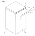
- Fig. 1 shows a perspective view of a refrigerator, such as a refrigerator or freezer in a stand construction with a body 30 and a door 31.
- the top of the body 30 is formed by a work surface 32, the front edge 33 is flush with the door 31.
- an opening is broken, in which a body 1 of a housing is inserted.
- the body 1 has approximately the shape of an elongated cuboid with an open front.
- a cover 2 of the housing is shown separated from the refrigerator. It comprises a cover plate 14, which covers the front edge 33 of the worktop for the most part in the assembled state, and an apron, the four of a back of the cover 14 at right angles projecting, mutually connected at corners webs 15, 16, 17 (see also Fig. 2 ) and is provided to engage in the assembled state in the body 1.
- Body 1 and lid 2 are injection molded from plastic.
- the housing formed by body 1 and lid 2 is provided to receive control circuits of the refrigerator and to shield them from insulation material which substantially completely fills the hollow walls of the appliance body 30 and the worktop 32 outside the housing body 1.
- the lid 2 breakthroughs or windows may be formed at appropriate locations through which Controls the control circuits led out or display elements are visible; they are not shown in the figure.
- Fig. 2 shows a section through the lid 2 and the body 1.
- the sectional plane extends in the longitudinal direction of the body 1 and the lid 2, so that one of the two extending on a longitudinal side of the lid 2 webs 17 and a wide side wall 18 of the body 1 in plan view and on the narrow sides of the lid 2 extending webs 15, 16 and narrow side walls 19, 20 of the body 1 can be seen in section.
- End portions of the body 1 and lid 2 are - in the same orientation as in Fig. 2 - in Fig. 3 shown enlarged.
- a detent 3 adjacent to the open front of the body 1 in the interior thereof.
- the detent 3 has a remote from the open front locking surface. 4
- a complementary to the locking lug 3 locking lug 5 is formed on an outer side of the web 16 of the lid 2.
- the latch 5 has, as in the enlarged view of Fig. 3 better to recognize a staircase-shaped contour with a plurality of each of the cover plate 14 facing locking surfaces. 6
- the two locking lugs 3, 5 is at least one elastically displaceable in the longitudinal direction of the body 1 and the lid 2 elastically.
- a tongue can be cut free from the side wall 19 or the web 16, at the free end of which the catch nose 3 or 5 is placed.
- the tongue is cut free in the web 16, since a corresponding free cut in the side wall 19 would impair the tightness of the body 1 with respect to insulating material surrounding it.
- an undercut 7 is formed, into which, as shown, a formed on the web 15 of the lid 2 pin 9 can be inserted.
- a step with a sharp edge 22 is formed on a side facing away from the open front of the body 1 surface 21 of the undercut 7 . This touched by the pin 9 edge 22 defines a for Cutting plane of Figures 2 . 3 vertical axis about which the lid 2 is pivotable with respect to the body 1.
- a rib 10 into the interior of the body 1 before.
- the rib 10 extends parallel to the narrow side wall 19 at a small distance from this.
- the ribs 10 may be transverse to the cutting plane of the Fig. 2 or 3 extend over the entire height of the body 1 and be fused together; However, in order to not unnecessarily limit the space available in the body 1 for accommodating electronic circuits, they are preferably separated from each other, and their height across the cutting plane is preferably not more than a few millimeters.
- a slot or a groove 8 is formed in the two webs 17 of the lid 2 is adjacent to the web 16 and parallel to this.
- the grooves 8 each have at their end facing away from the cover plate 14 a funnel-shaped widened inlet portion 11. This inlet portion 11 is provided to, when the lid 2 from his in the Figures 2 . 3 shown position on the body 1 is pivoted to facilitate the penetration of the ribs 10 in the grooves 8.
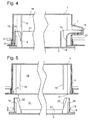
- Fig. 4 indicates in Fig. 3 analog sectional views of the end portions of the body 1 and cover 2 in a latched state.
- the cover 2 is held on the one hand by the engagement of the pin 9 in the undercut 7 and on the other hand by the contact of the locking surfaces 4, 6 of the two locking lugs 3, 5 with each other on the body 1.
- the width of the groove 8 is adapted with a small tolerance to the thickness of the rib 10, so that the cover 2 is held on the body 1 at most with a small clearance in the longitudinal direction, which is smaller than the extension of the locking surfaces 4, 6 in this direction ,
- the engagement of the ribs 10 in the grooves 8 prevents a displacement of the body 1 and lid 2 against each other, in which the overlap between the locking surfaces 4, 6 is lost, and regardless of any dimensional tolerances of the body 1 and the lid 2 in a between the grooves 8 and ribs 10 on the one hand and undercut 7 and pin 9 on the other hand extending area.
- Fig. 5 shows a part of a body 1 and to be mounted on an opening of the body cover 2 according to a second embodiment of the invention.
- webs 16 which carry on its outer side an elastic gurdrlindbare latching lug 5, as in Fig. 3 shown, provided on both narrow sides of the lid 2 to engage behind a detent 3 on the narrow sides of the opening of the body 1.
- Fig. 3 Of the two wide side walls 18 of the body 1 are each two ribs 10 in mutually mirror-image arrangement in the interior of the body 1 before.
- the extending along the broad sides of the lid 2 webs 17 each have a recess 21 which extends over a distance corresponding to the ribs 10 width, so that on both sides of the recess 21 projecting tongues 22, when attaching the lid 1 on the body. 2 engage with little play between each one of the ribs 10 and the adjacent narrow side 19 of the body 1 and thus prevent slipping of the locking surfaces 4, 6 of the body and lid from each other.
Landscapes
- Engineering & Computer Science (AREA)
- Chemical & Material Sciences (AREA)
- Combustion & Propulsion (AREA)
- Mechanical Engineering (AREA)
- General Engineering & Computer Science (AREA)
- Physics & Mathematics (AREA)
- Thermal Sciences (AREA)
- Closures For Containers (AREA)
- Casings For Electric Apparatus (AREA)
- Brushes (AREA)
- Cookers (AREA)
Description
- Die vorliegende Erfindung betrifft ein Haushaltsgerät mit einem Gehäuse, das einen Korpus und einen Deckel aufweist, der an einer Öffnung des Korpus befestigbar ist, indem eine erste Rastfläche des Deckels eine zweite Rastfläche des Korpus hintergreift. Ein Haushaltsgerät, bei dem des Weiteren der Deckel einen Vorsprung aufweist, ist aus
DE 102004045475 bekannt. - Bei elektrischen Haushaltsgeräten wie etwa Kältegeräten ist es bekannt, an der Innenseite eines Deckels elektrische oder elektronische Bauteile anzubringen, die zur Steuerung des Gerätes dienen, und den Deckel am Korpus des Geräts so zu montieren, dass die Bauteile geschützt in einem Hohlraum im Innern des Korpus zu liegen kommen.
Ein solcher Deckel muss sicher mit dem ihn tragenden Korpus verbunden sein, um sicherzustellen, dass ein Benutzer keine Spannung führenden Teile berühren kann. Auch wenn die elektrischen oder elektronischen Bauteile oder allgemein Spannung führende Oberflächen getrennt vom Deckel in dem Hohlraum des Korpus angebracht sind, muss sichergestellt sein, das der Deckel sich nicht unbeabsichtigt vom Korpus lösen und die Spannung führenden Oberflächen frei geben kann. Herkömmlicherweise wird diese Anforderung erfüllt, indem der Deckel mit Hilfe von Schrauben am Korpus befestigt wird. Um das äußere Erscheinungsbild des Gerätes nicht zu beeinträchtigen, müssen die hierfür erforderlichen Schraublöcher am Deckel mit Hilfe von Abdeckteilen kaschiert werden. - An sich wäre es denkbar, den Deckel am Korpus des Haushaltsgeräts zu verrasten und dadurch die Verschraubung überflüssig zu machen. In der Praxis erweist es sich aufgrund der großen Abmessungen des Deckels - dieser kann sich über die gesamte Breite des Gerätekorpus erstrecken - und der Maßungenauigkeit und Verformbarkeit des Deckels, die daraus resultieren, als schwierig, eine ausreichend sichere Verrastung zu gewährleisten.
- Aufgabe der vorliegenden Erfindung ist es daher, des Gehäuse des Haushaltsgerätsmit einem Korpus und einem am Korpus verrastbaren Deckel bereit zu stellen, bei dem trotz eventueller Maßungenauigkeit oder Verformbarkeit von Deckel und Korpus eine sichere Verrastung von Deckel und Korpus gewährleistet ist.
- Die Aufgabe wird gemäß Anspruch 1 gelöst.
Der Abstand von Vorsprung und Aussparung von den Rastflächen kann so klein wie nötig gemacht werden, damit Fertigungstoleranzen dieses Abstands oder eine Verformbarkeit des zwischen Vorsprung und Aussparung einerseits und den Rastflächen andererseits liegenden Bereichs des Deckels die Verrastung nicht gefährden können; der restliche Bereich des Deckels kann verformbar oder in seinen Abmessungen großzügig toleriert sein, ohne dass dies einen Einfluss auf die Sicherheit der Verrastung hat. - Einer ersten Ausgestaltung der Erfindung zufolge weisen Korpus und Deckel Konturen auf, die in einer ersten Orientierung des Deckels zum Korpus ineinander einführbar sind und die im eingeführten Zustand eine Schwenkbewegung des Deckels in eine zweite Orientierung erlauben, durch die die Rastflächen aneinander verrasten.
- Zweckmäßigerweise definieren die ineinandergreifenden Konturen auch eine Achse der Schwenkbewegung.
- Vorzugsweise ist die am Deckel ausgebildete Kontur eine Ausbuchtung, und die am Korpus ausgebildete Kontur ist eine Hinterschneidung, in die die Ausbuchtung einführbar ist.
- Eine Achse für die Schwenkbewegung des Deckels kann einfach durch den Eingriff der Konturen von Korpus und Deckel ineinander definiert sein.
- Zweckmäßigerweise überlappen die beiden Konturen in der zu den Rastflächen parallelen Richtung auf einer Länge, die größer ist als das Spiel, mit dem Vorsprung und Aussparung in dieser Richtung ineinander greifen. Somit kann der Eingriff der Konturen ineinander nicht verloren gehen, wenn sich der Deckel in Bezug auf das Gehäuse im Rahmen des Spiels zwischen Vorsprung und Aussparung verschiebt.
- Der erfinderische Gedanke sieht weiterhin vor, dass Vorsprung und Aussparung einen kleineren Abstand zu den Rastflächen als zu den beiden Konturen aufweisen. Der Abschnitt des Deckels zwischen Vorsprung und Aussparung einerseits und den Rastflächen andererseits hat somit kleinere Abmessungen als der Abschnitt zwischen Vorsprung und Aussparung einerseits und den ineinandergreifenden Konturen andererseits. Daher kann der erstere Abschnitt mit vergleichsweise engen Toleranzen gefertigt werden, und es genügt ein kleiner Überlapp zwischen den Rastflächen, um eine sichere Verrastung zu gewährleisten.
- Einer zweiten Ausgestaltung zufolge können Korpus und Deckel jeweils mehrere Rastflächen an einander gegenüberliegenden Rändern der Öffnung aufweisen; dies ermöglicht eine Verrastung des Deckels durch einfaches Aufstecken auf die Öffnung.
- Vorteilhafterweise weist von Deckel und Korpus mindestens der eine eine Mehrzahl von gestaffelten Rastflächen auf. Indem die Rastfläche des jeweils anderen von Deckel und Korpus eine aus dieser Mehrzahl von gestaffelten Rastflächen hintergreift, kann der Deckel in verschiedenen Positionen zum Korpus verrastet werden.
- Zweckmäßigerweise ist die Rastfläche des Deckels in einer zu ihr tangentialen Richtung elastisch verschiebbar. Die Rastfläche des Deckels kann so beim Montieren des Deckels am Korpus leicht an der Rastfläche des Korpus vorbei geführt werden.
- Bei einer bevorzugten Ausgestaltung der Erfindung kann der Vorsprung als Rippe und die Aussparung als Nut ausgebildet sein. Auf diese Weise wird die Verschiebbarkeit des Deckels am Korpus in entgegengesetzten Richtungen begrenzt.
- Dabei ist es zweckmäßig, wenn die Nut einen aufgeweiteten Eingangsbereich aufweist. Das Einführen der Rippe in die Nut wird so erleichtert.
- Weitere Merkmale und Vorteile der Erfindung ergeben sich aus der nachfolgenden Beschreibung eines Ausführungsbeispiels unter Bezugnahme auf die beigefügten Figuren. Es zeigen:
- Fig. 1
- eine perspektivische Ansicht eines Kältegeräts, in dem ein erfindungsgemäßes Gehäuse eingebaut ist.
- Fig. 2
- einen Schnitt durch einen Teil eines Korpus und durch einen Deckel des erfindungsgemäßen Gehäuses in einer ersten Orientierung, in welcher der Deckel schwenkbar in den Korpus eingreift;
- Fig. 3
- eine vergrößerte Darstellung von Details der
Fig. 2 ; - Fig. 4
- eine zu
Fig. 3 analoge Darstellung in einer zweiten Orientierung, in der Korpus und den Deckel aneinander verrastet sind; und - Fig. 5
- eine zu
Fig. 3 analoge Darstellung gemäß einer zweiten Ausgestaltung der Erfindung. -
Fig. 1 zeigt eine perspektivische Ansicht eines Kältegeräts wie etwa eines Kühl- oder Gefrierschranks in Standbauweise mit einem Korpus 30 und einer Tür 31. Die Oberseite des Korpus 30 ist durch eine Arbeitsplatte 32 gebildet, deren vorderer Rand 33 bündig mit der Tür 31 abschließt. In den vorderen Rand 33 ist eine Öffnung gebrochen, in die ein Korpus 1 eines Gehäuses eingefügt ist. Der Korpus 1 hat in etwa die Form eines langgestreckten Quaders mit offener Vorderseite. Ein Deckel 2 des Gehäuses ist vom Kältegerät getrennt dargestellt. Er umfasst eine Abdeckplatte 14, die im montierten Zustand den vorderen Rand 33 der Arbeitsplatte größtenteils überdeckt, sowie eine Schürze, die vier von einer Rückseite der Abdeckplatte 14 rechtwinklig abstehende, untereinander an Ecken verbundene Stege 15, 16, 17 (siehe auchFig. 2 ) umfasst und vorgesehen ist, um im montierten Zustand in den Korpus 1 einzugreifen. - Korpus 1 und Deckel 2 sind aus Kunststoff spritzgeformt.
- Das durch Korpus 1 und Deckel 2 gebildete Gehäuse ist vorgesehen, um Steuerschaltungen des Kältegeräts aufzunehmen und sie von Isolationsmaterial abzuschirmen, das die hohlen Wände des Gerätekorpus 30 und die Arbeitsplatte 32 außerhalb des Gehäusekorpus 1 im wesentlichen vollständig ausfüllt. In dem Deckel 2 können an geeigneten Stellen Durchbrüche oder Fenster gebildet sein, durch die Bedienelemente der Steuerschaltungen herausgeführt oder Anzeigeelemente sichtbar sind; sie sind in der Fig. nicht dargestellt.
-
Fig. 2 zeigt einen Schnitt durch den Deckel 2 und den Korpus 1. Die Schnittebene verläuft in Längsrichtung des Korpus 1 und des Deckels 2, so dass einer der zwei sich an einer Längsseite des Deckels 2 verlaufenden Stege 17 sowie eine breite Seitenwand 18 des Korpus 1 in Draufsicht und die sich an den Schmalseiten des Deckels 2 erstreckenden Stege 15, 16 sowie schmale Seitenwände 19, 20 des Korpus 1 im Schnitt zu sehen sind. Endbereiche von Korpus 1 und Deckel 2 sind - in derselben Orientierung zueinander wie inFig. 2 - inFig. 3 vergrößert gezeigt. - Von der schmalen Seitenwand 19 des Korpus 1 steht eine Rastnase 3 benachbart zur offenen Vorderseite des Korpus 1 in dessen Innenraum vor. Die Rastnase 3 hat eine von der offenen Vorderseite abgewandte Rastfläche 4.
- Eine zu der Rastnase 3 komplementäre Rastnase 5 ist an einer Außenseite des Steges 16 des Deckels 2 gebildet. Die Rastnase 5 hat, wie in der vergrößerten Darstellung von
Fig. 3 besser zu erkennen, eine treppenförmige Kontur mit mehreren jeweils der Abdeckplatte 14 zugewandten Rastflächen 6. - Von den zwei Rastnasen 3, 5 ist wenigstens eine elastisch in Längsrichtung des Korpus 1 bzw. des Deckels 2 elastisch verschiebbar. Um eine solche Verschiebbarkeit zu erreichen, kann zum Beispiel aus der Seitenwand 19 oder dem Steg 16 eine Zunge freigeschnitten sein, an deren freiem Ende die Rastnase 3 oder 5 platziert ist. Im vorliegenden Fall ist die Zunge in dem Steg 16 freigeschnitten, da ein entsprechender Freischnitt in der Seitenwand 19 die Dichtigkeit des Korpus 1 gegenüber ihn umgebendem Isolationsmaterial beeinträchtigen würde.
- An der der Seitenwand 19 gegenüberliegenden schmalen Seitenwand 20 des Korpus 1 ist eine Hinterschneidung 7 gebildet, in die, wie gezeigt, ein an dem Steg 15 des Deckels 2 geformter Zapfen 9 einführbar ist. An einer von der offenen Vorderseite des Korpus 1 abgewandten Oberfläche 21 der Hinterschneidung 7 ist eine Stufe mit einer scharfen Kante 22 gebildet. Diese von dem Zapfen 9 berührte Kante 22 definiert eine zur Schnittebene der
Figuren 2 ,3 senkrechte Achse, um welche der Deckel 2 in Bezug auf den Korpus 1 schwenkbar ist. - Von den beiden breiten Seitenwänden 18 des Korpus 1 steht jeweils eine Rippe 10 ins Innere des Korpus 1 vor. Die Rippe 10 erstreckt sich parallel zur schmalen Seitenwand 19 in geringem Abstand von dieser. Die Rippen 10 können sich quer zur Schnittebene der
Fig. 2 oder3 über die gesamte Höhe des Korpus 1 erstrecken und miteinander verschmolzen sein; um den im Korpus 1 für die Unterbringung von elektronischen Schaltungen verfügbaren Platz nicht unnötig zu beschränken, sind sie jedoch vorzugsweise voneinander getrennt, und ihre Höhe quer zur Schnittebene beträgt vorzugsweise nicht mehr als einige Millimeter. - In den zwei Stegen 17 des Deckels 2 ist jeweils benachbart zum Steg 16 und parallel zu diesem ein Schlitz oder eine Nut 8 gebildet. Die Nuten 8 haben jeweils an ihrem von der Abdeckplatte 14 abgewandten Ende einen trichterförmig aufgeweiteten Einlassbereich 11. Dieser Einlassbereich 11 ist vorgesehen, um, wenn der Deckel 2 aus seiner in den
Figuren 2 ,3 gezeigten Stellung auf den Korpus 1 zu geschwenkt wird, das Eindringen der Rippen 10 in die Nuten 8 zu erleichtern. -
Fig. 4 zeigt in zuFig. 3 analogen Schnittdarstellungen die Endbereiche von Korpus 1 und Deckel 2 in einem aneinander verrasteten Zustand. Der Deckel 2 ist einerseits durch den Eingriff des Zapfens 9 in die Hinterschneidung 7 und andererseits durch den Kontakt der Rastflächen 4, 6 der zwei Rastnasen 3, 5 miteinander am Korpus 1 gehalten. Die Breite der Nut 8 ist mit geringer Toleranz an die Stärke der Rippe 10 angepasst, so dass der Deckel 2 am Korpus 1 allenfalls mit einem geringen Spiel in der Längsrichtung gehalten ist, das kleiner ist als die Ausdehnung der Rastflächen 4, 6 in dieser Richtung. Somit verhindert der Eingriff der Rippen 10 in die Nuten 8 eine Verschiebung von Korpus 1 und Deckel 2 gegeneinander, bei der der Überlapp zwischen den Rastflächen 4, 6 verloren geht, und dies unabhängig von eventuellen Abmessungstoleranzen des Korpus 1 und des Deckels 2 in einem sich zwischen den Nuten 8 und Rippen 10 einerseits und Hinterschneidung 7 und Zapfen 9 andererseits erstreckenden Bereich. Um eine sichere Verrastung des Deckels 2 zu gewährleisten, genügt es daher, wenn die Abmessungstoleranzen im Bereich zwischen den Rastnasen 3, 7 einerseits und Nuten 8 und Rippen 10 andererseits klein im Verhältnis zu den Abmessungen der Rastflächen 4, 6 gehalten werden; eine Anforderung, die aufgrund der kleinen Abmessungen dieses Bereiches leicht zu erfüllen ist. -
Fig. 5 zeigt einen Teil eines Korpus 1 und eines an einer Öffnung des Korpus zu montierenden Deckels 2 gemäß einer zweiten Ausgestaltung der Erfindung. Bei dieser Ausgestaltung sind Stege 16, die an ihrer Außenseite eine elastische zurückdrängbare Rastnase 5 tragen, wie inFig. 3 dargestellt, an beiden Schmalseiten des Deckels 2 vorgesehen, um eine Rastnase 3 an den Schmalseiten der Öffnung des Korpus 1 zu hintergreifen. Von den beiden breiten Seitenwänden 18 des Korpus 1 stehen jeweils zwei Rippen 10 in zueinander spiegelbildlicher Anordnung ins Innere des Korpus 1 vor. Die sich entlang der Breitseiten des Deckels 2 erstreckenden Stege 17 weisen jeweils eine Aussparung 21 auf, die sich über eine dem Abstand der Rippen 10 entsprechende Breite erstreckt, so dass beiderseits der Aussparung 21 vorspringende Zungen 22, beim Aufstecken des Deckels 1 auf den Korpus 2 mit geringem Spiel zwischen jeweils eine der Rippen 10 und die dieser benachbarte Schmalseite 19 des Korpus 1 eingreifen und so ein Abrutschen der Rastflächen 4, 6 von Korpus und Deckel voneinander verhindern.
Claims (11)
- Haushaltsgerät mit einem Gehäuse das einen Korpus (1) und einen Deckel (2) aufweist, der an einer Öffnung des Korpus (1) befestigbar ist, indem eine erste Rastfläche (6) des Deckels (2) eine zweite Rastfläche (4) des Korpus (1) hintergreift, wobei von Deckel (2) und Korpus (1) jeweils der eine eine Aussparung (8) und der andere einen Vorsprung (10) aufweist, und Vorsprung (10) und Aussparung (8) mit einem Spiel in einer zu den Rastflächen (4; 6) parallelen Richtung ineinandergreifen, das kleiner als die Ausdehnung der Rastflächen (4; 6) in besagter Richtung ist.
- Haushaltsgerät nach Anspruch 1, dadurch gekennzeichnet, dass Korpus (1) und Deckel (2) Konturen (7; 9) aufweisen, die in einer ersten Orientierung des Deckels (2) zum Korpus (1) ineinander einführbar sind und im ineinander eingeführten Zustand eine Schwenkbewegung des Deckels (2) in eine zweite Orientierung erlauben, durch die die Rastflächen (4, 6) aneinander verrasten.
- Haushaltsgerät nach Anspruch 2, dadurch gekennzeichnet, dass die ineinander eingreifenden Konturen (7; 9) des Korpus (1) und des Deckels (2) eine Schwenkachse der Schwenkbewegung des Deckels (2) definieren.
- Haushaltsgerät nach Anspruch 2 oder 3, dadurch gekennzeichnet, dass die Kontur (9), die am Deckel (2) ausgebildet ist, eine Ausbuchtung (9) ist und die Kontur (7), die am Korpus (1) ausgebildet ist, eine Hinterschneidung (7) ist, und die Ausbuchtung (9) in die Hinterschneidung (8) einführbar ist.
- Haushaltsgerät nach einem der Ansprüche 2 bis 4, dadurch gekennzeichnet, dass die beiden Konturen (7, 9) in der zu den Rastflächen (3; 4) parallelen Richtung auf einer Länge überlappen, die größer ist als das Spiel, mit dem Vorsprung (10) und Aussparung (8) in dieser Richtung ineinander greifen.
- Haushaltsgerät nach einem der vorhergehenden Ansprüche, dadurch gekennzeichnet, dass Vorsprung (10) und Aussparung (8) einen kleineren Abstand zu den Rastflächen (4; 6) als zu den beiden Konturen (7; 9) aufweisen.
- Haushaltsgerät nach Anspruch 1, dadurch gekennzeichnet, dass Korpus (1) und Deckel (2) jeweils mehrere Rastflächen (6) an einander gegenüberliegenden Rändern der Öffnung aufweisen.
- Haushaltsgerät nach einem der vorhergehenden Ansprüche, dadurch gekennzeichnet, dass von Deckel (2) und Korpus (1) mindestens der eine eine Mehrzahl von gestaffelten Rastflächen (6) aufweist.
- Haushaltsgerät nach einem der vorhergehenden Ansprüche, dadurch gekennzeichnet, dass die Rastfläche (6) des Deckels (2) in einer zu ihr tangentialen Richtung elastisch verschiebbar ist.
- Haushaltsgerät nach einem der vorhergehenden Ansprüche, dadurch gekennzeichnet, dass der Vorsprung (10) als Rippe (10) und die Aussparung (8) als Nut (8) ausgebildet sind.
- Haushaltsgerät nach Anspruch 8, dadurch gekennzeichnet, dass die Nut (8) einen aufgeweiteten Eingangsbereich (11) aufweist.
Applications Claiming Priority (2)
| Application Number | Priority Date | Filing Date | Title |
|---|---|---|---|
| DE102006052449A DE102006052449A1 (de) | 2006-11-07 | 2006-11-07 | Gehäuse für ein Haushaltsgerät |
| PCT/EP2007/061687 WO2008055818A2 (de) | 2006-11-07 | 2007-10-30 | Gehäuse für ein haushaltsgerät |
Publications (2)
| Publication Number | Publication Date |
|---|---|
| EP2087302A2 EP2087302A2 (de) | 2009-08-12 |
| EP2087302B1 true EP2087302B1 (de) | 2010-03-31 |
Family
ID=39264949
Family Applications (1)
| Application Number | Title | Priority Date | Filing Date |
|---|---|---|---|
| EP07822041A Active EP2087302B1 (de) | 2006-11-07 | 2007-10-30 | Gehäuse für ein haushaltsgerät |
Country Status (7)
| Country | Link |
|---|---|
| EP (1) | EP2087302B1 (de) |
| CN (1) | CN101535751B (de) |
| AT (1) | ATE462945T1 (de) |
| DE (2) | DE102006052449A1 (de) |
| ES (1) | ES2341590T3 (de) |
| RU (1) | RU2447381C2 (de) |
| WO (1) | WO2008055818A2 (de) |
Families Citing this family (5)
| Publication number | Priority date | Publication date | Assignee | Title |
|---|---|---|---|---|
| KR102379996B1 (ko) * | 2017-08-31 | 2022-03-29 | 삼성전자주식회사 | 식기세척기 |
| CN111979715B (zh) * | 2019-05-23 | 2023-08-08 | 青岛海尔洗涤电器有限公司 | 一种洗衣机台面固定结构 |
| CN111979714B (zh) * | 2019-05-23 | 2023-08-01 | 青岛海尔洗涤电器有限公司 | 一种洗衣机台面固定结构 |
| CN111979717B (zh) * | 2019-05-23 | 2023-08-08 | 青岛海尔洗涤电器有限公司 | 一种洗衣机台面固定结构 |
| CN111979716B (zh) * | 2019-05-23 | 2023-08-01 | 青岛海尔洗涤电器有限公司 | 一种洗衣机台面固定结构 |
Family Cites Families (8)
| Publication number | Priority date | Publication date | Assignee | Title |
|---|---|---|---|---|
| SU1515014A1 (ru) * | 1987-04-01 | 1989-10-15 | Предприятие П/Я А-7075 | Холодильна машина |
| DE3743192A1 (de) * | 1987-12-19 | 1989-06-29 | Asea Brown Boveri | Befestigungssystem fuer abdeckungen |
| CN2203272Y (zh) * | 1994-03-26 | 1995-07-12 | 英业达股份有限公司 | 可开合盖子 |
| FR2848378B1 (fr) * | 2002-12-04 | 2006-07-14 | Legrand Sa | Boitier du genre comportant deux elements destines a etre rendus solidaires l'un de l'autre de facon sure |
| RU42635U1 (ru) * | 2004-08-12 | 2004-12-10 | Федеральное государственное унитарное предприятие "Производственное объединение "Завод имени Серго" | Морозильник-ларь |
| DE102004045475A1 (de) * | 2004-09-20 | 2006-03-30 | BSH Bosch und Siemens Hausgeräte GmbH | Bauteil zur Montage an einer hinterschäumten Wand und damit ausgestattetes Kältegerät |
| JP2006162140A (ja) * | 2004-12-06 | 2006-06-22 | Toshiba Corp | 冷蔵庫 |
| DE202006013230U1 (de) * | 2006-08-29 | 2006-11-16 | BSH Bosch und Siemens Hausgeräte GmbH | Kabeldurchführung |
-
2006
- 2006-11-07 DE DE102006052449A patent/DE102006052449A1/de not_active Withdrawn
-
2007
- 2007-10-30 DE DE502007003355T patent/DE502007003355D1/de active Active
- 2007-10-30 CN CN2007800414607A patent/CN101535751B/zh not_active Expired - Fee Related
- 2007-10-30 AT AT07822041T patent/ATE462945T1/de active
- 2007-10-30 EP EP07822041A patent/EP2087302B1/de active Active
- 2007-10-30 ES ES07822041T patent/ES2341590T3/es active Active
- 2007-10-30 RU RU2009119056/13A patent/RU2447381C2/ru not_active IP Right Cessation
- 2007-10-30 WO PCT/EP2007/061687 patent/WO2008055818A2/de not_active Ceased
Also Published As
| Publication number | Publication date |
|---|---|
| ES2341590T3 (es) | 2010-06-22 |
| WO2008055818A2 (de) | 2008-05-15 |
| RU2009119056A (ru) | 2010-12-20 |
| CN101535751A (zh) | 2009-09-16 |
| DE502007003355D1 (de) | 2010-05-12 |
| CN101535751B (zh) | 2011-01-26 |
| WO2008055818A3 (de) | 2008-09-12 |
| EP2087302A2 (de) | 2009-08-12 |
| DE102006052449A1 (de) | 2008-05-08 |
| RU2447381C2 (ru) | 2012-04-10 |
| ATE462945T1 (de) | 2010-04-15 |
Similar Documents
| Publication | Publication Date | Title |
|---|---|---|
| EP2059748B1 (de) | Einbau-kältegerät mit ausgabevorrichtung | |
| WO2007062948A1 (de) | Gehäuse für ein haushaltsgerät | |
| EP2145146B1 (de) | Behälter mit einer unterteilungsvorrichtung | |
| EP2010841A2 (de) | Mehrteiliges haushaltsgerät | |
| EP2087302B1 (de) | Gehäuse für ein haushaltsgerät | |
| DE102019218224A1 (de) | Haushaltskühlgerät mit einem Anschlussstift oder einem Arretierelement in einer Wandeinheit eines Gehäuses eines Eisbereiters sowie Verfahren zur Montage eines Gehäuses eines Eisbereiters | |
| WO2016066381A1 (de) | Haushaltsgerät mit einer eingabevorrichtung und einer kodiervorrichtung | |
| EP2702338B1 (de) | Kühlgutbehälter und kältegerät mit einem kühlgutbehälter | |
| DE202008005353U1 (de) | Gehäuse für ein Haushaltsgerät | |
| DE102005057153A1 (de) | Vorrichtung zum Verdecken eines Spalts | |
| EP2290308B1 (de) | Kältegerät | |
| EP2756245B1 (de) | Kältegerät, insbesondere haushaltskältegerät | |
| EP2206420A1 (de) | Bedienblende für ein elektrogerät | |
| DE102019218222A1 (de) | Haushaltskühlgerät mit einem Vorsprung als Kondenswasser-Tropfleiste in einer Wand eines Eisbereiters | |
| DE202016007457U1 (de) | Drehriegelschloss | |
| EP2281159B1 (de) | Tür für ein haushaltsgerät | |
| WO2011042307A2 (de) | Kältegerät mit ventilatorbaugruppe | |
| EP2607825A2 (de) | Haushaltsgerätekombination | |
| DE102013221297A1 (de) | Haushaltsgerät mit Elektronikmodul | |
| EP3002533A2 (de) | Befestigungssatz zur befestigung eines haushaltsgerätes, haushaltsgerät und verfahren zur befestigung eines haushaltsgerätes | |
| DE102024204133B4 (de) | Anschlussbaugruppe für ein Haushaltsgerät und Haushaltsgerät | |
| EP3832233B1 (de) | Haushaltskältegerät mit einem hinterlegteil und verfahren zum herstellen des haushaltskältegerätes | |
| DE102019208996B4 (de) | Kodierrahmen mit Klappverschluss, Bausatz und Elektrogerät | |
| EP2650988A2 (de) | Berührungsschutzabdeckung für elektrische Anlagen | |
| EP1580846B1 (de) | Verbindungselement für elektrische Leiter |
Legal Events
| Date | Code | Title | Description |
|---|---|---|---|
| PUAI | Public reference made under article 153(3) epc to a published international application that has entered the european phase |
Free format text: ORIGINAL CODE: 0009012 |
|
| 17P | Request for examination filed |
Effective date: 20090608 |
|
| AK | Designated contracting states |
Kind code of ref document: A2 Designated state(s): AT BE BG CH CY CZ DE DK EE ES FI FR GB GR HU IE IS IT LI LT LU LV MC MT NL PL PT RO SE SI SK TR |
|
| GRAP | Despatch of communication of intention to grant a patent |
Free format text: ORIGINAL CODE: EPIDOSNIGR1 |
|
| DAX | Request for extension of the european patent (deleted) | ||
| GRAS | Grant fee paid |
Free format text: ORIGINAL CODE: EPIDOSNIGR3 |
|
| GRAA | (expected) grant |
Free format text: ORIGINAL CODE: 0009210 |
|
| AK | Designated contracting states |
Kind code of ref document: B1 Designated state(s): AT BE BG CH CY CZ DE DK EE ES FI FR GB GR HU IE IS IT LI LT LU LV MC MT NL PL PT RO SE SI SK TR |
|
| REG | Reference to a national code |
Ref country code: CH Ref legal event code: EP Ref country code: GB Ref legal event code: FG4D Free format text: NOT ENGLISH |
|
| REG | Reference to a national code |
Ref country code: IE Ref legal event code: FG4D |
|
| REF | Corresponds to: |
Ref document number: 502007003355 Country of ref document: DE Date of ref document: 20100512 Kind code of ref document: P |
|
| REG | Reference to a national code |
Ref country code: ES Ref legal event code: FG2A Ref document number: 2341590 Country of ref document: ES Kind code of ref document: T3 |
|
| REG | Reference to a national code |
Ref country code: NL Ref legal event code: VDEP Effective date: 20100331 |
|
| PG25 | Lapsed in a contracting state [announced via postgrant information from national office to epo] |
Ref country code: LT Free format text: LAPSE BECAUSE OF FAILURE TO SUBMIT A TRANSLATION OF THE DESCRIPTION OR TO PAY THE FEE WITHIN THE PRESCRIBED TIME-LIMIT Effective date: 20100331 |
|
| LTIE | Lt: invalidation of european patent or patent extension |
Effective date: 20100331 |
|
| PG25 | Lapsed in a contracting state [announced via postgrant information from national office to epo] |
Ref country code: LV Free format text: LAPSE BECAUSE OF FAILURE TO SUBMIT A TRANSLATION OF THE DESCRIPTION OR TO PAY THE FEE WITHIN THE PRESCRIBED TIME-LIMIT Effective date: 20100331 Ref country code: SI Free format text: LAPSE BECAUSE OF FAILURE TO SUBMIT A TRANSLATION OF THE DESCRIPTION OR TO PAY THE FEE WITHIN THE PRESCRIBED TIME-LIMIT Effective date: 20100331 Ref country code: PL Free format text: LAPSE BECAUSE OF FAILURE TO SUBMIT A TRANSLATION OF THE DESCRIPTION OR TO PAY THE FEE WITHIN THE PRESCRIBED TIME-LIMIT Effective date: 20100331 Ref country code: FI Free format text: LAPSE BECAUSE OF FAILURE TO SUBMIT A TRANSLATION OF THE DESCRIPTION OR TO PAY THE FEE WITHIN THE PRESCRIBED TIME-LIMIT Effective date: 20100331 |
|
| REG | Reference to a national code |
Ref country code: IE Ref legal event code: FD4D |
|
| PG25 | Lapsed in a contracting state [announced via postgrant information from national office to epo] |
Ref country code: CY Free format text: LAPSE BECAUSE OF FAILURE TO SUBMIT A TRANSLATION OF THE DESCRIPTION OR TO PAY THE FEE WITHIN THE PRESCRIBED TIME-LIMIT Effective date: 20100331 Ref country code: EE Free format text: LAPSE BECAUSE OF FAILURE TO SUBMIT A TRANSLATION OF THE DESCRIPTION OR TO PAY THE FEE WITHIN THE PRESCRIBED TIME-LIMIT Effective date: 20100331 Ref country code: SE Free format text: LAPSE BECAUSE OF FAILURE TO SUBMIT A TRANSLATION OF THE DESCRIPTION OR TO PAY THE FEE WITHIN THE PRESCRIBED TIME-LIMIT Effective date: 20100331 Ref country code: RO Free format text: LAPSE BECAUSE OF FAILURE TO SUBMIT A TRANSLATION OF THE DESCRIPTION OR TO PAY THE FEE WITHIN THE PRESCRIBED TIME-LIMIT Effective date: 20100331 Ref country code: NL Free format text: LAPSE BECAUSE OF FAILURE TO SUBMIT A TRANSLATION OF THE DESCRIPTION OR TO PAY THE FEE WITHIN THE PRESCRIBED TIME-LIMIT Effective date: 20100331 |
|
| PG25 | Lapsed in a contracting state [announced via postgrant information from national office to epo] |
Ref country code: SK Free format text: LAPSE BECAUSE OF FAILURE TO SUBMIT A TRANSLATION OF THE DESCRIPTION OR TO PAY THE FEE WITHIN THE PRESCRIBED TIME-LIMIT Effective date: 20100331 Ref country code: IS Free format text: LAPSE BECAUSE OF FAILURE TO SUBMIT A TRANSLATION OF THE DESCRIPTION OR TO PAY THE FEE WITHIN THE PRESCRIBED TIME-LIMIT Effective date: 20100731 Ref country code: CZ Free format text: LAPSE BECAUSE OF FAILURE TO SUBMIT A TRANSLATION OF THE DESCRIPTION OR TO PAY THE FEE WITHIN THE PRESCRIBED TIME-LIMIT Effective date: 20100331 |
|
| PG25 | Lapsed in a contracting state [announced via postgrant information from national office to epo] |
Ref country code: PT Free format text: LAPSE BECAUSE OF FAILURE TO SUBMIT A TRANSLATION OF THE DESCRIPTION OR TO PAY THE FEE WITHIN THE PRESCRIBED TIME-LIMIT Effective date: 20100802 Ref country code: IE Free format text: LAPSE BECAUSE OF FAILURE TO SUBMIT A TRANSLATION OF THE DESCRIPTION OR TO PAY THE FEE WITHIN THE PRESCRIBED TIME-LIMIT Effective date: 20100331 Ref country code: DK Free format text: LAPSE BECAUSE OF FAILURE TO SUBMIT A TRANSLATION OF THE DESCRIPTION OR TO PAY THE FEE WITHIN THE PRESCRIBED TIME-LIMIT Effective date: 20100331 |
|
| PLBE | No opposition filed within time limit |
Free format text: ORIGINAL CODE: 0009261 |
|
| STAA | Information on the status of an ep patent application or granted ep patent |
Free format text: STATUS: NO OPPOSITION FILED WITHIN TIME LIMIT |
|
| 26N | No opposition filed |
Effective date: 20110104 |
|
| BERE | Be: lapsed |
Owner name: BSH BOSCH UND SIEMENS HAUSGERATE G.M.B.H. Effective date: 20101031 |
|
| PG25 | Lapsed in a contracting state [announced via postgrant information from national office to epo] |
Ref country code: MC Free format text: LAPSE BECAUSE OF NON-PAYMENT OF DUE FEES Effective date: 20101031 |
|
| PG25 | Lapsed in a contracting state [announced via postgrant information from national office to epo] |
Ref country code: BE Free format text: LAPSE BECAUSE OF NON-PAYMENT OF DUE FEES Effective date: 20101031 |
|
| PG25 | Lapsed in a contracting state [announced via postgrant information from national office to epo] |
Ref country code: IT Free format text: LAPSE BECAUSE OF NON-PAYMENT OF DUE FEES Effective date: 20101030 Ref country code: MT Free format text: LAPSE BECAUSE OF FAILURE TO SUBMIT A TRANSLATION OF THE DESCRIPTION OR TO PAY THE FEE WITHIN THE PRESCRIBED TIME-LIMIT Effective date: 20100331 |
|
| REG | Reference to a national code |
Ref country code: CH Ref legal event code: PL |
|
| PG25 | Lapsed in a contracting state [announced via postgrant information from national office to epo] |
Ref country code: CH Free format text: LAPSE BECAUSE OF NON-PAYMENT OF DUE FEES Effective date: 20111031 Ref country code: LI Free format text: LAPSE BECAUSE OF NON-PAYMENT OF DUE FEES Effective date: 20111031 |
|
| PG25 | Lapsed in a contracting state [announced via postgrant information from national office to epo] |
Ref country code: BG Free format text: LAPSE BECAUSE OF FAILURE TO SUBMIT A TRANSLATION OF THE DESCRIPTION OR TO PAY THE FEE WITHIN THE PRESCRIBED TIME-LIMIT Effective date: 20100331 Ref country code: LU Free format text: LAPSE BECAUSE OF NON-PAYMENT OF DUE FEES Effective date: 20101030 Ref country code: HU Free format text: LAPSE BECAUSE OF FAILURE TO SUBMIT A TRANSLATION OF THE DESCRIPTION OR TO PAY THE FEE WITHIN THE PRESCRIBED TIME-LIMIT Effective date: 20101001 |
|
| PG25 | Lapsed in a contracting state [announced via postgrant information from national office to epo] |
Ref country code: BG Free format text: LAPSE BECAUSE OF FAILURE TO SUBMIT A TRANSLATION OF THE DESCRIPTION OR TO PAY THE FEE WITHIN THE PRESCRIBED TIME-LIMIT Effective date: 20100630 |
|
| REG | Reference to a national code |
Ref country code: AT Ref legal event code: MM01 Ref document number: 462945 Country of ref document: AT Kind code of ref document: T Effective date: 20121031 |
|
| PG25 | Lapsed in a contracting state [announced via postgrant information from national office to epo] |
Ref country code: AT Free format text: LAPSE BECAUSE OF NON-PAYMENT OF DUE FEES Effective date: 20121031 |
|
| PG25 | Lapsed in a contracting state [announced via postgrant information from national office to epo] |
Ref country code: GR Free format text: LAPSE BECAUSE OF FAILURE TO SUBMIT A TRANSLATION OF THE DESCRIPTION OR TO PAY THE FEE WITHIN THE PRESCRIBED TIME-LIMIT Effective date: 20100331 |
|
| REG | Reference to a national code |
Ref country code: DE Ref legal event code: R081 Ref document number: 502007003355 Country of ref document: DE Owner name: BSH HAUSGERAETE GMBH, DE Free format text: FORMER OWNER: BSH BOSCH UND SIEMENS HAUSGERAETE GMBH, 81739 MUENCHEN, DE Effective date: 20150407 |
|
| REG | Reference to a national code |
Ref country code: ES Ref legal event code: PC2A Owner name: BSH HAUSGERATE GMBH Effective date: 20150609 |
|
| REG | Reference to a national code |
Ref country code: FR Ref legal event code: PLFP Year of fee payment: 9 |
|
| REG | Reference to a national code |
Ref country code: FR Ref legal event code: CD Owner name: BSH HAUSGERATE GMBH, DE Effective date: 20151022 |
|
| REG | Reference to a national code |
Ref country code: FR Ref legal event code: PLFP Year of fee payment: 10 |
|
| PGFP | Annual fee paid to national office [announced via postgrant information from national office to epo] |
Ref country code: FR Payment date: 20161025 Year of fee payment: 10 Ref country code: GB Payment date: 20161025 Year of fee payment: 10 |
|
| PGFP | Annual fee paid to national office [announced via postgrant information from national office to epo] |
Ref country code: ES Payment date: 20161025 Year of fee payment: 10 |
|
| GBPC | Gb: european patent ceased through non-payment of renewal fee |
Effective date: 20171030 |
|
| REG | Reference to a national code |
Ref country code: FR Ref legal event code: ST Effective date: 20180629 |
|
| PG25 | Lapsed in a contracting state [announced via postgrant information from national office to epo] |
Ref country code: GB Free format text: LAPSE BECAUSE OF NON-PAYMENT OF DUE FEES Effective date: 20171030 |
|
| PG25 | Lapsed in a contracting state [announced via postgrant information from national office to epo] |
Ref country code: FR Free format text: LAPSE BECAUSE OF NON-PAYMENT OF DUE FEES Effective date: 20171031 |
|
| REG | Reference to a national code |
Ref country code: ES Ref legal event code: FD2A Effective date: 20181221 |
|
| PG25 | Lapsed in a contracting state [announced via postgrant information from national office to epo] |
Ref country code: ES Free format text: LAPSE BECAUSE OF NON-PAYMENT OF DUE FEES Effective date: 20171031 |
|
| PGFP | Annual fee paid to national office [announced via postgrant information from national office to epo] |
Ref country code: DE Payment date: 20211031 Year of fee payment: 15 |
|
| PGFP | Annual fee paid to national office [announced via postgrant information from national office to epo] |
Ref country code: TR Payment date: 20221021 Year of fee payment: 16 Ref country code: IT Payment date: 20221031 Year of fee payment: 16 |
|
| REG | Reference to a national code |
Ref country code: DE Ref legal event code: R119 Ref document number: 502007003355 Country of ref document: DE |
|
| PG25 | Lapsed in a contracting state [announced via postgrant information from national office to epo] |
Ref country code: DE Free format text: LAPSE BECAUSE OF NON-PAYMENT OF DUE FEES Effective date: 20230503 |
|
| PG25 | Lapsed in a contracting state [announced via postgrant information from national office to epo] |
Ref country code: IT Free format text: LAPSE BECAUSE OF NON-PAYMENT OF DUE FEES Effective date: 20231030 |
|
| PG25 | Lapsed in a contracting state [announced via postgrant information from national office to epo] |
Ref country code: IT Free format text: LAPSE BECAUSE OF NON-PAYMENT OF DUE FEES Effective date: 20231030 |