EP2087786A1 - Plaque de sol pouvant être chauffée pour un sol d'écurie - Google Patents
Plaque de sol pouvant être chauffée pour un sol d'écurie Download PDFInfo
- Publication number
- EP2087786A1 EP2087786A1 EP09001513A EP09001513A EP2087786A1 EP 2087786 A1 EP2087786 A1 EP 2087786A1 EP 09001513 A EP09001513 A EP 09001513A EP 09001513 A EP09001513 A EP 09001513A EP 2087786 A1 EP2087786 A1 EP 2087786A1
- Authority
- EP
- European Patent Office
- Prior art keywords
- tube
- bottom plate
- plate according
- profiled tube
- wall
- Prior art date
- Legal status (The legal status is an assumption and is not a legal conclusion. Google has not performed a legal analysis and makes no representation as to the accuracy of the status listed.)
- Withdrawn
Links
- 239000007788 liquid Substances 0.000 claims abstract description 10
- 241001465754 Metazoa Species 0.000 claims abstract description 6
- 229910001220 stainless steel Inorganic materials 0.000 claims abstract description 4
- 239000010935 stainless steel Substances 0.000 claims abstract description 4
- 238000010438 heat treatment Methods 0.000 claims description 38
- 238000009413 insulation Methods 0.000 claims description 17
- -1 polyethylene Polymers 0.000 claims description 4
- 239000000843 powder Substances 0.000 claims description 4
- 229910010271 silicon carbide Inorganic materials 0.000 claims description 4
- HBMJWWWQQXIZIP-UHFFFAOYSA-N silicon carbide Chemical compound [Si+]#[C-] HBMJWWWQQXIZIP-UHFFFAOYSA-N 0.000 claims description 4
- VYPSYNLAJGMNEJ-UHFFFAOYSA-N silicon dioxide Inorganic materials O=[Si]=O VYPSYNLAJGMNEJ-UHFFFAOYSA-N 0.000 claims description 4
- 229910052500 inorganic mineral Inorganic materials 0.000 claims description 3
- 239000011707 mineral Substances 0.000 claims description 3
- 239000010453 quartz Substances 0.000 claims description 3
- 150000004760 silicates Chemical class 0.000 claims description 3
- 239000004698 Polyethylene Substances 0.000 claims description 2
- 239000004743 Polypropylene Substances 0.000 claims description 2
- 239000004033 plastic Substances 0.000 claims description 2
- 229920003023 plastic Polymers 0.000 claims description 2
- 229920000573 polyethylene Polymers 0.000 claims description 2
- 229920001155 polypropylene Polymers 0.000 claims description 2
- XLYOFNOQVPJJNP-UHFFFAOYSA-N water Substances O XLYOFNOQVPJJNP-UHFFFAOYSA-N 0.000 description 5
- 238000005452 bending Methods 0.000 description 2
- 239000000919 ceramic Substances 0.000 description 2
- 239000002184 metal Substances 0.000 description 2
- 229910052580 B4C Inorganic materials 0.000 description 1
- 0 CCCC(CC)[C@](C)C*CCCCC**CIN Chemical compound CCCC(CC)[C@](C)C*CCCCC**CIN 0.000 description 1
- 239000006004 Quartz sand Substances 0.000 description 1
- 238000009825 accumulation Methods 0.000 description 1
- 230000036760 body temperature Effects 0.000 description 1
- INAHAJYZKVIDIZ-UHFFFAOYSA-N boron carbide Chemical compound B12B3B4C32B41 INAHAJYZKVIDIZ-UHFFFAOYSA-N 0.000 description 1
- 239000004020 conductor Substances 0.000 description 1
- 239000012777 electrically insulating material Substances 0.000 description 1
- 239000000835 fiber Substances 0.000 description 1
- 238000009434 installation Methods 0.000 description 1
- 238000004519 manufacturing process Methods 0.000 description 1
- 239000000463 material Substances 0.000 description 1
- 238000013021 overheating Methods 0.000 description 1
- 229920000642 polymer Polymers 0.000 description 1
Images


Classifications
-
- A—HUMAN NECESSITIES
- A01—AGRICULTURE; FORESTRY; ANIMAL HUSBANDRY; HUNTING; TRAPPING; FISHING
- A01K—ANIMAL HUSBANDRY; AVICULTURE; APICULTURE; PISCICULTURE; FISHING; REARING OR BREEDING ANIMALS, NOT OTHERWISE PROVIDED FOR; NEW BREEDS OF ANIMALS
- A01K1/00—Housing animals; Equipment therefor
- A01K1/015—Floor coverings, e.g. bedding-down sheets ; Stable floors
- A01K1/0158—Floor heating or cooling systems
Definitions
- the invention relates to a heatable bottom plate for a stable floor, in particular for a pigsty, consisting of a plate-shaped, a cavity forming plate body, the top is formed as a lying surface for the animals and passes through its filled with a liquid heat transfer medium cavity at least one metallic heating tube, which can be connected to an external heat source.
- Such a heatable bottom plate is made of DE 202 03 466 U1 known.
- Such indirectly heatable bottom plates have over directly heatable bottom plates, in which even in the plate body fürströmkanäle for warm water are formed (see, eg EP 0 601 282 B1 or DE 60 2004 002 238 T2 ) has the advantage that the heat supplied is uniformly distributed by the heat transfer medium located in the cavity of the plate over the serving as a lying surface for the animals top of the bottom plate.
- the heating tube itself can be heated by any heating media, that is, by flowing hot water or steam or possibly also electrically by a keepssflowerdraht, which runs in the interior of the heating tube.
- the invention proposes, starting from a bottom plate of the type mentioned above, that the heating tube is formed as a profiled tube with respect to a cylindrical tube enlarged surface, preferably as a twisted or corrugated tube.
- a profiled tube better maintains the required stiffness, even if it is bent within the cavity by a tight bending radius.
- the profiled tube is much more flexible than a cylindrical tube, which facilitates handling when inserted into the cavity of the plate body.
- the use of a profiled tube as a heating tube thus also offers advantages in the production of the heated bottom plate.
- a particularly preferred embodiment of the invention provides that the profiled tube is made of stainless steel and has a wall thickness of 0.1 to 0.6 mm.
- the profiling results in the corrugated pipe or swirl tube from Wandeinformept that extend either annular around the tube axis or helical to the tube axis.
- other surface profiling profiles of the profiled tube are also conceivable.
- the profiled tube is arranged in the interior of the cavity of the plate body at a distance from the bottom of this cavity. This ensures that the heating tube does not come into direct contact with the material of the plate body and that sufficient passage cross-sections remain between the outside of the heating tube and the bottom of the plate body, through which the heat transfer medium can flow freely. Of course, this free cross-section is further increased by the profiling of the heating tube.
- a particularly preferred embodiment of the invention provides that in the interior of the profiled tube a resistance heating wire runs and that in the space between the lovedsSchdraht and the wall of the profiled tube insulation is arranged, which holds the lovedsSchdraht at a distance from the wall of the profiled tube and at the same time produces a large-area heat-transferring contact between the lovedsSchdraht and the wall of the profiled tube.
- a good heat-conducting insulation between the resistance heating wire and the wall of the profiled tube also improves the heat transfer into the liquid heat transfer medium of the plate body and prevents heat accumulation in the interior of the profiled tube.
- this insulation ensures that the resistance heating wire is kept at a distance from the wall of the profiled tube and nowhere in contact with this wall, which could lead to local overheating and damage to the wall of the profiled tube.
- the insulation expediently consists of a thermally conductive mineral powder filling the gap between the resistance heating wire and the wall of the profiled tube, which may consist, for example, of crystalline silicates, quartz, silicon carbide or boron carbide.
- This Mineral powder fixes the resistance heating wire approximately in the middle of the profiled tube and at the same time ensures uniform heat transfer in all directions towards the wall of the profiled tube.
- the insulation can also consist of a cylindrical heating jacket enclosing the resistance heating wire, which is supported on the inwardly projecting surface areas of the profiled tube.
- This insulating shell is also made of an electrically insulating material, which is still good thermal conductivity and ensures good heat transfer to the contacting wall portions of the profiled tube.
- a further improvement of the heat transfer from the resistance heating wire to the wall of the profiled tube can be brought about by the fact that the insulation is supplemented by a heat-conducting liquid filled in the profiled tube. This liquid fills all remaining approximately in the insulation cavities and complements the desired good heat transfer from the resistance heating on the profiled tube.
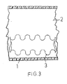
- the plate body 1 encloses a cavity 2, in which a U-shaped bent heating tube is arranged.
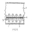
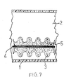
- This heating tube is made of stainless steel, has a wall thickness of 0.1 to 0.6 mm and is formed overall as a profiled tube 3, namely as a corrugated tube ( Figures 3 and 6 ) or as a swirl tube ( FIG. 7 ).
- this formed as a profiled tube 3 heating tube has a distance from the bottom of the plate body 1, in such a way that everywhere a sufficient flow area for the cavity 2 located in the heat transfer medium, for. B. water remains.
- the profiled tube 3 is provided with annular Wandeinformmaschine which extend annularly around the tube axis.
- the wave crests extending between the wall recesses are in FIG. 6 indicated by dashed lines.
- FIG. 7 has the profiled tube 3 in contrast Wandeinformept that extend helically to the tube axis. It is therefore designed as a swirl tube. Again, located between the Wandeinformept wave crests are indicated by dashed lines.
- the manufactured as a profiled tube 3 heating tube led out down from the plate body.
- any heating media eg. As hot water, steam or the like can be connected.
- FIGS. 4 to 7 extends through the interior of the corrugated tube 3 formed as a heating tube at a distance from the walls of an electrical resistance heating wire 4, in a good thermal conductivity insulation. 5 is embedded.
- This thermally conductive insulation consists for example of quartz sand, suitable crystalline silicates, silicon carbide or from Bohrcarbid and has the function to fix the lovedsSdraht 4 approximately in the middle of the profiled tube 3 and at the same time for a good heat transfer from the lovedsSchdraht 4 to the wall of the profiled tube 3, which in turn located in the cavity 2 heat transfer medium, for. B. heated water.
- the profiled tube 3 and theticiansSchdraht 4 are led out with their ends down from your plate body 1 and there provided in a manner not shown with a power connection for the heating current.
- the insulation may also consist of a surrounding the lovedsSchdraht 4 cylindrical shell, which is supported on the inwardly projecting surfaces of the profiled tube 3.
- This cylindrical shell consists of an electrically insulating, but still highly thermally conductive material, such as ceramic, ceramic fibers or a thermally conductive powder, eg. As quartz, silicon carbide, Bohrcarbid or the like high-filled polymer.
- the insulation can be filled with an electrically insulating, but good thermal conductivity liquid.
- the additional measure is conceivable and expedient in all the above-discussed embodiments of the insulation.
- the plate body 1 is provided on its underside and at its edges with not shown in the drawing connection options for an installation system.
- the upper side of the plate body 1 is designed as a lying surface for the animals.
Landscapes
- Life Sciences & Earth Sciences (AREA)
- Environmental Sciences (AREA)
- Zoology (AREA)
- Animal Husbandry (AREA)
- Biodiversity & Conservation Biology (AREA)
- Housing For Livestock And Birds (AREA)
- Steam Or Hot-Water Central Heating Systems (AREA)
- Floor Finish (AREA)
- Resistance Heating (AREA)
Applications Claiming Priority (2)
| Application Number | Priority Date | Filing Date | Title |
|---|---|---|---|
| DE200820001603 DE202008001603U1 (de) | 2008-02-04 | 2008-02-04 | Beheizbare Bodenplatte für einen Stallboden |
| DE202008014958U DE202008014958U1 (de) | 2008-02-04 | 2008-11-11 | Beheizbare Bodenplatte für einen Stallboden |
Publications (1)
| Publication Number | Publication Date |
|---|---|
| EP2087786A1 true EP2087786A1 (fr) | 2009-08-12 |
Family
ID=39400206
Family Applications (1)
| Application Number | Title | Priority Date | Filing Date |
|---|---|---|---|
| EP09001513A Withdrawn EP2087786A1 (fr) | 2008-02-04 | 2009-02-04 | Plaque de sol pouvant être chauffée pour un sol d'écurie |
Country Status (2)
| Country | Link |
|---|---|
| EP (1) | EP2087786A1 (fr) |
| DE (2) | DE202008001603U1 (fr) |
Cited By (1)
| Publication number | Priority date | Publication date | Assignee | Title |
|---|---|---|---|---|
| EP2689659A3 (fr) * | 2012-07-23 | 2016-05-11 | Mik International Ag | Plaque de sol chauffante |
Families Citing this family (2)
| Publication number | Priority date | Publication date | Assignee | Title |
|---|---|---|---|---|
| CN103262801A (zh) * | 2013-06-10 | 2013-08-28 | 乔昌玉 | 养殖用地暖板块及其生产方法 |
| FR3076978B1 (fr) | 2018-01-22 | 2021-09-24 | Bioret Agri Logette Confort | Matelas pour le confort thermique des animaux dans une enceinte d'elevage |
Citations (7)
| Publication number | Priority date | Publication date | Assignee | Title |
|---|---|---|---|---|
| LU82956A1 (de) * | 1980-09-12 | 1981-03-26 | Feist Artus | Aus einem flexiblen oder steifen kunststoff bestehendes rohr zum transport eines waermetraegers |
| US4377083A (en) * | 1979-09-18 | 1983-03-22 | Shepherd Dale H | Tube corrugating apparatus and method |
| EP0542315A1 (fr) * | 1991-11-15 | 1993-05-19 | Hewing GmbH | Tuyau pour le transport des liquides froids ou chauds |
| EP0601282B1 (fr) | 1992-09-21 | 2000-04-05 | Heinrich Michel | Pièce moulée, en particulier pour surface portant des animaux dans des étables |
| JP2000337786A (ja) * | 1999-05-27 | 2000-12-08 | Teigu:Kk | 熱交換器の伝熱管 |
| DE20203466U1 (de) | 2002-03-04 | 2002-07-18 | Pollmeyer, Thomas, 33758 Schloß Holte-Stukenbrock | Heizbare Bodenplatte für Stallungen |
| DE602004002238T2 (de) | 2003-06-19 | 2006-12-28 | Rotecna, S.A., Agramunt | Beheiztes Bodenmodul für Viehställe |
-
2008
- 2008-02-04 DE DE200820001603 patent/DE202008001603U1/de not_active Expired - Lifetime
- 2008-11-11 DE DE202008014958U patent/DE202008014958U1/de not_active Expired - Lifetime
-
2009
- 2009-02-04 EP EP09001513A patent/EP2087786A1/fr not_active Withdrawn
Patent Citations (7)
| Publication number | Priority date | Publication date | Assignee | Title |
|---|---|---|---|---|
| US4377083A (en) * | 1979-09-18 | 1983-03-22 | Shepherd Dale H | Tube corrugating apparatus and method |
| LU82956A1 (de) * | 1980-09-12 | 1981-03-26 | Feist Artus | Aus einem flexiblen oder steifen kunststoff bestehendes rohr zum transport eines waermetraegers |
| EP0542315A1 (fr) * | 1991-11-15 | 1993-05-19 | Hewing GmbH | Tuyau pour le transport des liquides froids ou chauds |
| EP0601282B1 (fr) | 1992-09-21 | 2000-04-05 | Heinrich Michel | Pièce moulée, en particulier pour surface portant des animaux dans des étables |
| JP2000337786A (ja) * | 1999-05-27 | 2000-12-08 | Teigu:Kk | 熱交換器の伝熱管 |
| DE20203466U1 (de) | 2002-03-04 | 2002-07-18 | Pollmeyer, Thomas, 33758 Schloß Holte-Stukenbrock | Heizbare Bodenplatte für Stallungen |
| DE602004002238T2 (de) | 2003-06-19 | 2006-12-28 | Rotecna, S.A., Agramunt | Beheiztes Bodenmodul für Viehställe |
Cited By (1)
| Publication number | Priority date | Publication date | Assignee | Title |
|---|---|---|---|---|
| EP2689659A3 (fr) * | 2012-07-23 | 2016-05-11 | Mik International Ag | Plaque de sol chauffante |
Also Published As
| Publication number | Publication date |
|---|---|
| DE202008001603U1 (de) | 2008-05-15 |
| DE202008014958U1 (de) | 2009-03-05 |
Similar Documents
| Publication | Publication Date | Title |
|---|---|---|
| EP2458298A2 (fr) | Chauffe-eau électrique | |
| DE102005019211B3 (de) | Rohrheizkörper mit konischer Heizleiterwendel | |
| DE202007015294U1 (de) | Flächenheizung, insbesondere Fußbodenheizung | |
| EP2190255B1 (fr) | Cartouche de chauffage tubulaire électrique | |
| EP1431460A1 (fr) | Finisseur et élément chauffant | |
| EP2087786A1 (fr) | Plaque de sol pouvant être chauffée pour un sol d'écurie | |
| CH666539A5 (de) | Waermetauscherrohr und daraus gebildeter waermetauscher. | |
| DE3542507C2 (fr) | ||
| WO2014000852A1 (fr) | Système de gestion de chaleur | |
| EP2020576A2 (fr) | Collecteur solaire destiné au réchauffement d'un liquide | |
| DE1902575A1 (de) | Waermeaustauscher | |
| DE3541641A1 (de) | Rohrheizkoerper-heizeinrichtung sowie verfahren zu deren herstellung | |
| DE10323944A1 (de) | Prozessbehälter mit Kühlelementen | |
| DE3221348A1 (de) | Heizelement mit zylindrischer wandung | |
| EP0568813B1 (fr) | Elément de construction pour l'isolation thermique de bâtiments | |
| WO2009071501A1 (fr) | Tuyau pourvu d'une surface latérale extérieure modifiée par un profil de surface | |
| DE1615455A1 (de) | Heizelement fuer elektrische Kabeloefen zur Beheizung einer Gas- oder Fluessigkeitsstroemung | |
| DE202006011151U1 (de) | Plattenförmige Vorrichtung zur Aufnahme von Leitungen | |
| DE102020006821A1 (de) | Kompaktheizer mit Mantelrohrheizkörper | |
| DE20017369U1 (de) | Betonkerntemperierungsmodule | |
| DE102018107054B4 (de) | Chopper-Widerstand mit Lastwiderstand | |
| DE102008058355A1 (de) | Solarkollektor zum Erwärmen einer Flüssigkeit | |
| DE20118726U1 (de) | Strahlungselement | |
| DE2914747A1 (de) | Umhuellter widerstand fuer konvektionsheizer | |
| DE19519121C1 (de) | Vorrichtung zum Erhitzen von Flüssigkeiten |
Legal Events
| Date | Code | Title | Description |
|---|---|---|---|
| PUAI | Public reference made under article 153(3) epc to a published international application that has entered the european phase |
Free format text: ORIGINAL CODE: 0009012 |
|
| AK | Designated contracting states |
Kind code of ref document: A1 Designated state(s): AT BE BG CH CY CZ DE DK EE ES FI FR GB GR HR HU IE IS IT LI LT LU LV MC MK MT NL NO PL PT RO SE SI SK TR |
|
| AX | Request for extension of the european patent |
Extension state: AL BA RS |
|
| RIN1 | Information on inventor provided before grant (corrected) |
Inventor name: WEBER-MONECKE, JOHANNES Inventor name: ERTEL, THOMAS |
|
| AKX | Designation fees paid |
Designated state(s): AT BE BG CH CY CZ DE DK EE ES FI FR GB GR HR HU IE IS IT LI LT LU LV MC MK MT NL NO PL PT RO SE SI SK TR |
|
| STAA | Information on the status of an ep patent application or granted ep patent |
Free format text: STATUS: THE APPLICATION IS DEEMED TO BE WITHDRAWN |
|
| 18D | Application deemed to be withdrawn |
Effective date: 20100213 |