EP2089458B1 - Verfahren, system und dessen verwendung zur bekämpfung der rollneigung bei mehrschichtigen bahnen - Google Patents
Verfahren, system und dessen verwendung zur bekämpfung der rollneigung bei mehrschichtigen bahnen Download PDFInfo
- Publication number
- EP2089458B1 EP2089458B1 EP07843204A EP07843204A EP2089458B1 EP 2089458 B1 EP2089458 B1 EP 2089458B1 EP 07843204 A EP07843204 A EP 07843204A EP 07843204 A EP07843204 A EP 07843204A EP 2089458 B1 EP2089458 B1 EP 2089458B1
- Authority
- EP
- European Patent Office
- Prior art keywords
- web
- endplate
- coating
- curing
- roller
- Prior art date
- Legal status (The legal status is an assumption and is not a legal conclusion. Google has not performed a legal analysis and makes no representation as to the accuracy of the status listed.)
- Not-in-force
Links
Images







Classifications
-
- B—PERFORMING OPERATIONS; TRANSPORTING
- B05—SPRAYING OR ATOMISING IN GENERAL; APPLYING FLUENT MATERIALS TO SURFACES, IN GENERAL
- B05D—PROCESSES FOR APPLYING FLUENT MATERIALS TO SURFACES, IN GENERAL
- B05D3/00—Pretreatment of surfaces to which liquids or other fluent materials are to be applied; After-treatment of applied coatings, e.g. intermediate treating of an applied coating preparatory to subsequent applications of liquids or other fluent materials
- B05D3/12—Pretreatment of surfaces to which liquids or other fluent materials are to be applied; After-treatment of applied coatings, e.g. intermediate treating of an applied coating preparatory to subsequent applications of liquids or other fluent materials by mechanical means
-
- B—PERFORMING OPERATIONS; TRANSPORTING
- B05—SPRAYING OR ATOMISING IN GENERAL; APPLYING FLUENT MATERIALS TO SURFACES, IN GENERAL
- B05D—PROCESSES FOR APPLYING FLUENT MATERIALS TO SURFACES, IN GENERAL
- B05D7/00—Processes, other than flocking, specially adapted for applying liquids or other fluent materials to particular surfaces or for applying particular liquids or other fluent materials
- B05D7/02—Processes, other than flocking, specially adapted for applying liquids or other fluent materials to particular surfaces or for applying particular liquids or other fluent materials to macromolecular substances, e.g. rubber
- B05D7/04—Processes, other than flocking, specially adapted for applying liquids or other fluent materials to particular surfaces or for applying particular liquids or other fluent materials to macromolecular substances, e.g. rubber to surfaces of films or sheets
-
- B—PERFORMING OPERATIONS; TRANSPORTING
- B65—CONVEYING; PACKING; STORING; HANDLING THIN OR FILAMENTARY MATERIAL
- B65H—HANDLING THIN OR FILAMENTARY MATERIAL, e.g. SHEETS, WEBS, CABLES
- B65H23/00—Registering, tensioning, smoothing or guiding webs
- B65H23/02—Registering, tensioning, smoothing or guiding webs transversely
- B65H23/022—Registering, tensioning, smoothing or guiding webs transversely by tentering devices
-
- B—PERFORMING OPERATIONS; TRANSPORTING
- B65—CONVEYING; PACKING; STORING; HANDLING THIN OR FILAMENTARY MATERIAL
- B65H—HANDLING THIN OR FILAMENTARY MATERIAL, e.g. SHEETS, WEBS, CABLES
- B65H23/00—Registering, tensioning, smoothing or guiding webs
- B65H23/02—Registering, tensioning, smoothing or guiding webs transversely
- B65H23/022—Registering, tensioning, smoothing or guiding webs transversely by tentering devices
- B65H23/025—Registering, tensioning, smoothing or guiding webs transversely by tentering devices by rollers
-
- B—PERFORMING OPERATIONS; TRANSPORTING
- B65—CONVEYING; PACKING; STORING; HANDLING THIN OR FILAMENTARY MATERIAL
- B65H—HANDLING THIN OR FILAMENTARY MATERIAL, e.g. SHEETS, WEBS, CABLES
- B65H23/00—Registering, tensioning, smoothing or guiding webs
- B65H23/04—Registering, tensioning, smoothing or guiding webs longitudinally
- B65H23/34—Apparatus for taking-out curl from webs
-
- B—PERFORMING OPERATIONS; TRANSPORTING
- B65—CONVEYING; PACKING; STORING; HANDLING THIN OR FILAMENTARY MATERIAL
- B65H—HANDLING THIN OR FILAMENTARY MATERIAL, e.g. SHEETS, WEBS, CABLES
- B65H26/00—Warning or safety devices, e.g. automatic fault detectors, stop-motions, for web-advancing mechanisms
-
- C—CHEMISTRY; METALLURGY
- C08—ORGANIC MACROMOLECULAR COMPOUNDS; THEIR PREPARATION OR CHEMICAL WORKING-UP; COMPOSITIONS BASED THEREON
- C08J—WORKING-UP; GENERAL PROCESSES OF COMPOUNDING; AFTER-TREATMENT NOT COVERED BY SUBCLASSES C08B, C08C, C08F, C08G or C08H
- C08J7/00—Chemical treatment or coating of shaped articles made of macromolecular substances
- C08J7/04—Coating
- C08J7/0427—Coating with only one layer of a composition containing a polymer binder
-
- B—PERFORMING OPERATIONS; TRANSPORTING
- B29—WORKING OF PLASTICS; WORKING OF SUBSTANCES IN A PLASTIC STATE IN GENERAL
- B29C—SHAPING OR JOINING OF PLASTICS; SHAPING OF MATERIAL IN A PLASTIC STATE, NOT OTHERWISE PROVIDED FOR; AFTER-TREATMENT OF THE SHAPED PRODUCTS, e.g. REPAIRING
- B29C55/00—Shaping by stretching, e.g. drawing through a die; Apparatus therefor
- B29C55/02—Shaping by stretching, e.g. drawing through a die; Apparatus therefor of plates or sheets
- B29C55/023—Shaping by stretching, e.g. drawing through a die; Apparatus therefor of plates or sheets using multilayered plates or sheets
-
- B—PERFORMING OPERATIONS; TRANSPORTING
- B29—WORKING OF PLASTICS; WORKING OF SUBSTANCES IN A PLASTIC STATE IN GENERAL
- B29C—SHAPING OR JOINING OF PLASTICS; SHAPING OF MATERIAL IN A PLASTIC STATE, NOT OTHERWISE PROVIDED FOR; AFTER-TREATMENT OF THE SHAPED PRODUCTS, e.g. REPAIRING
- B29C55/00—Shaping by stretching, e.g. drawing through a die; Apparatus therefor
- B29C55/02—Shaping by stretching, e.g. drawing through a die; Apparatus therefor of plates or sheets
- B29C55/023—Shaping by stretching, e.g. drawing through a die; Apparatus therefor of plates or sheets using multilayered plates or sheets
- B29C55/026—Shaping by stretching, e.g. drawing through a die; Apparatus therefor of plates or sheets using multilayered plates or sheets of preformed plates or sheets coated with a solution, a dispersion or a melt of thermoplastic material
-
- B—PERFORMING OPERATIONS; TRANSPORTING
- B65—CONVEYING; PACKING; STORING; HANDLING THIN OR FILAMENTARY MATERIAL
- B65H—HANDLING THIN OR FILAMENTARY MATERIAL, e.g. SHEETS, WEBS, CABLES
- B65H2301/00—Handling processes for sheets or webs
- B65H2301/50—Auxiliary process performed during handling process
- B65H2301/51—Modifying a characteristic of handled material
- B65H2301/511—Processing surface of handled material upon transport or guiding thereof, e.g. cleaning
- B65H2301/5114—Processing surface of handled material upon transport or guiding thereof, e.g. cleaning coating
-
- B—PERFORMING OPERATIONS; TRANSPORTING
- B65—CONVEYING; PACKING; STORING; HANDLING THIN OR FILAMENTARY MATERIAL
- B65H—HANDLING THIN OR FILAMENTARY MATERIAL, e.g. SHEETS, WEBS, CABLES
- B65H2301/00—Handling processes for sheets or webs
- B65H2301/50—Auxiliary process performed during handling process
- B65H2301/51—Modifying a characteristic of handled material
- B65H2301/512—Changing form of handled material
- B65H2301/5121—Bending, buckling, curling, bringing a curvature
- B65H2301/51212—Bending, buckling, curling, bringing a curvature perpendicularly to the direction of displacement of handled material, e.g. forming a loop
-
- B—PERFORMING OPERATIONS; TRANSPORTING
- B65—CONVEYING; PACKING; STORING; HANDLING THIN OR FILAMENTARY MATERIAL
- B65H—HANDLING THIN OR FILAMENTARY MATERIAL, e.g. SHEETS, WEBS, CABLES
- B65H2301/00—Handling processes for sheets or webs
- B65H2301/50—Auxiliary process performed during handling process
- B65H2301/51—Modifying a characteristic of handled material
- B65H2301/512—Changing form of handled material
- B65H2301/5124—Stretching; Tentering
-
- B—PERFORMING OPERATIONS; TRANSPORTING
- B65—CONVEYING; PACKING; STORING; HANDLING THIN OR FILAMENTARY MATERIAL
- B65H—HANDLING THIN OR FILAMENTARY MATERIAL, e.g. SHEETS, WEBS, CABLES
- B65H2301/00—Handling processes for sheets or webs
- B65H2301/50—Auxiliary process performed during handling process
- B65H2301/51—Modifying a characteristic of handled material
- B65H2301/512—Changing form of handled material
- B65H2301/5124—Stretching; Tentering
- B65H2301/51242—Stretching transversely; Tentering
-
- B—PERFORMING OPERATIONS; TRANSPORTING
- B65—CONVEYING; PACKING; STORING; HANDLING THIN OR FILAMENTARY MATERIAL
- B65H—HANDLING THIN OR FILAMENTARY MATERIAL, e.g. SHEETS, WEBS, CABLES
- B65H2701/00—Handled material; Storage means
- B65H2701/10—Handled articles or webs
- B65H2701/18—Form of handled article or web
- B65H2701/186—Several articles or webs processed together
- B65H2701/1864—Superposed webs
-
- C—CHEMISTRY; METALLURGY
- C08—ORGANIC MACROMOLECULAR COMPOUNDS; THEIR PREPARATION OR CHEMICAL WORKING-UP; COMPOSITIONS BASED THEREON
- C08J—WORKING-UP; GENERAL PROCESSES OF COMPOUNDING; AFTER-TREATMENT NOT COVERED BY SUBCLASSES C08B, C08C, C08F, C08G or C08H
- C08J2433/00—Characterised by the use of homopolymers or copolymers of compounds having one or more unsaturated aliphatic radicals, each having only one carbon-to-carbon double bond, and only one being terminated by only one carboxyl radical, or of salts, anhydrides, esters, amides, imides, or nitriles thereof; Derivatives of such polymers
Definitions
- the present disclosure generally relates to multi-layer webs and controlling curl in multi-layer webs, particularly, multi-layer webs in which at least one layer comprises a cured coating.
- Some multi-layer webs have a tendency to curl.
- Curl can be defined as the tendency of a web (or multi-layer web) to deviate from a generally flat or planar orientation when there are no external forces on the web. Curled webs can be viewed as a defective product and can be more difficult to handle in downstream web handling or manufacturing processes than flat webs. For example, processes such as laminating, inspecting, and converting can be more challenging with a curled web than with a flat web.
- some multi-layer webs that are formed of a coating applied to an underlying web are used in applications in which the non-coated side of the multi-layer web is coupled to another object such that the coated side of the multi-layer web faces outwardly.
- Such multi-layer webs tend to curl toward the coated side, which can cause problems with delamination.
- flat multi-layer webs, or webs that tend to curl to the non-coated side may be easier to apply, and may result in better adhesion, less delamination, and longer product lives.
- a particular amount and orientation of curvature is necessary.
- US 2006/182901 A1 is directed to a stretched cellulose ester film containing a cellulose ester and a plasticizer.
- US 2006/182901 A1 further describes a hard coat film comprising a stretched cellulose ester film containing a cellulose ester and a plasticizer, and an actinic ray-cured resin layer provided on the stretched cellulose ester film.
- US 2003/082977 A1 describes a transversely stretched nonwoven fabric being manufactured by transversely stretching a nonwoven fabric.
- an original web comprising a plurality of unoriented filaments is heated to a temperature higher than its stretch suitable temperature by 5 °C or more.
- the heated original web is stretched at a rate of 1.2 to 3 in its transverse direction to stretch the filaments of the original web with almost no molecular orientation involved.
- the original web stretched transversely at a rate of 1.2 to 3 is heated to the stretch suitable temperature and the original web is further stretched transversely at the stretch suitable temperature.
- web handling processes and systems that produce a multi-layer web having a desired curvature may reduce the problems described above and improve product quality and reduce manufacturing waste.
- the present invention is directed to a method and a web handling system for producing a multi-layer web having a desired curvature according to claims 1 and 3 as well as to the use of a web handling system according to claim 2.
- One aspect of the present disclosure is directed to a method for reducing strain-induced curl in a multi-layer web.
- the method can include providing a coated web that includes a coating applied to a web of indeterminate length, the coating being characterized by at least partially shrinking when cured.
- the method can further include curing the coating to form a multi-layer web, the multi-layer web including a strain induced by curing the coating.
- the method can further include stretching the web during curing of the coating, wherein stretching the web substantially cancels the strain induced by curing such that the resulting multi-layer web is substantially flat.
- the method can include providing a coated web that includes a coating applied to a web of indeterminate length.
- the method can further include curing the coating to form a multi-layer web, the multi-layer web including a strain induced by curing the coating.
- the method can further include stretching the web during curing of the coating to induce an opposing strain in the web that at least partially counteracts the strain induced by curing, such that the resulting multi-layer web has a desired curvature.
- Another aspect of the present disclosure is directed to a light-redirecting film having a thickness of less than about 300 ⁇ m and a curvature of less than about 0.1 m -1 .
- the web handling system can include a curing section configured to cure a coating applied to a web of indeterminate length to form a multi-layer web.
- the web handling system can further include a web stretching section configured to stretch the web to induce a strain in the web.
- the web stretching section can be located proximate the curing section and can be substantially coincident with the curing section, such that the web is stretched while the coating is cured.
- the present disclosure generally relates to multi-layer webs and controlling curl in multi-layer webs.
- at least one of the layers comprises a cured coating.
- some multi-layer webs are formed by applying a coating to an underlying web and then curing and/or drying the coating. Many coatings have a tendency to shrink upon drying and curing, while the underlying web remains substantially the same size, which can cause the resulting multi-layer web to curl toward the coated side. This phenomenon is illustrated in FIG. 1 , which schematically illustrates a prior art web coating process 10.
- the coating after being cured, has a Young's modulus that is less than or equal to that of the web.
- the maximum curvature generally occurs when the coating-to-web thickness ratio (i.e., the ratio of the coating thickness to the web thickness) is between about 0.5 and about 1.0. Generally, within this range, the curvature of the resulting multi-layer web increases with increasing coating-to-web thickness ratio.
- a web 11 of indeterminate length is coated in a coating process 12 to form a coated web 14 having a coating 16 applied to the web 11.
- the coating 16 is then cured in a curing process 18 to form a multi-layer web 20 formed of the coating 16' in a cured state coupled to the web 11.
- the multi-layer web 20 includes an undesirable curvature.
- the curvature of the multi-layer web 20 is a result of the shrinkage of the coating 16 upon being cured, while the underlying web 11 remains substantially the same size.
- the cured coating 16' of the multi-layer web 20 will be in tension. Over time, the stress on the coating 16' that occurs during use of the multi-layer web 20 may cause the coating 16' to crack or craze, leading to undesirable product life.
- Some approaches that have been used to try to control curl in multi-layer webs include (1) reformulating the coating chemistry to reduce shrinkage, (2) under-curing the coating to reduce shrinkage (3) increasing machine direction line tensions, (4) post-cure processes such as shrinking the web, and (5) increasing the thickness of the underlying web to increase the web's resistance to curling.
- Option 1 generally results in an undesirable compromise between coating functionality and shrinkage, e.g., a hardcoating that is not very hard.
- Option 2 generally results in a coating of lower strength that is less durable, less hard, and/or less tough.
- the coating because at least a portion of the coating is under-cured, it can include unreacted monomers, which can cause undesirable downstream reactions that may affect product quality.
- Option 3 is not always successful because increasing machine directional tension creates an increased cross-machine directional compression due to the Poisson effect, which can exacerbate cross-machine directional curl.
- Option 4 can be limited by the type of web used and the amount of shrinkage that is available with a given web.
- Option 5 can limit the types of webs that can be used and can be a limiting factor in new product design. In addition, thicker webs increase cost and are not always the most desirable for a given application or product.
- the multi-layer web has a curvature of less than about 10.0 m -1 , particularly, less than about 5.0 m -1 , and more particularly, less than about 2.0 m -1 . Furthermore, in some embodiments, the multi-layer web has a curvature less than about 1.0 m -1 , particularly, less than about 0.5 m -1 , and more particularly, less than about 0.1 m -1 .
- the multi-layer web has a radius of curvature greater than about 0.1 m, particularly, greater than about 0.2 m, and more particularly, greater than about 0.5 m. Furthermore, in some embodiments, the multi-layer web has a radius of curvature of greater than about 1 m, particularly, greater than about 2m, and more particularly, greater than about 10 m.
- the multi-layer web has a thickness of less than about 500 ⁇ m, particularly, less than about 300 ⁇ m, and more particularly, less than about 200 ⁇ m. In some embodiments, the multi-layer web has a thickness of less than about 125 ⁇ m, particularly, less than about 25 ⁇ m, and more particularly, less than about 14 ⁇ m.
- Co-owned U.S. Patent Application Publication Nos. 2005/0212173 and 2005/0246965 describe removing curl in coated webs by flexing or reverse flexing the coated web after the coating has been cured.
- some webs are brittle and some coatings become brittle after being cured.
- Exposing such a coating to bending or stretching processes after curing can cause the coating to crack and craze, rather than yield, which can lead to poor product quality and lifespan.
- stretching the multi-layer web after the coating has been cured is not necessarily preferred for some coatings and multi-layer webs.
- the present disclosure can be applied to a variety of webs and coatings.
- webs that can be used include, but are not limited to, webs formed of polymers, composite materials, wood pulp (e.g., paper), and combinations thereof.
- Polymeric webs can be formed of homopolymers or copolymers and can include, but are not limited to, polyethylene terephthalate (PET), polycarbonate (PC), polyolefins (e.g., polypropylene (PP), polyethylene (PE), etc.), and combinations thereof.
- Coatings can be formed of a variety of materials, including polymers, composite materials, and combinations thereof.
- polymer coatings include, but are not limited to, acrylate or epoxy coatings (e.g., acrylate or epoxy hardcoats).
- composite coatings include, but are not limited to, coatings that include particles or fibers (e.g., colloidal or fibrous metal or metal oxide particles.
- curing processes suitable for curing a coating can be used, depending on the type of coating used.
- examples of curing processes can include, but are not limited to, at least one of actinic radiation, UV radiation, visible-light radiation, electron beam radiation, X-ray radiation, IR radiation, heat, and combinations thereof.
- the multi-layer webs of the present disclosure can be used in a variety of applications.
- the multi-layer webs can include light-redirecting films (e.g., brightness enhancement films (e.g., prismatic-structured films), turning films, and diffusing films), multi-layer optical films, polarization films, barrier films, protective films, and combinations thereof, all of which can be used in electronic displays (e.g., liquid crystal displays (LCDs), monitors, touch screens, personal digital assistants (PDAs), cellular telephones, etc.).
- the multi-layer web includes a light-redirecting film having a thickness of less than about 300 ⁇ m and a curvature of less than about 0.1 m -1 .
- Additional examples of applications in which multi-layer webs of the present disclosure can be used include traffic control film applications, graphic film applications, other protective or barrier film application (e.g., applications in the architectural and/or transportation industries), and combinations thereof.
- FIG. 2 illustrates a web handling processes 100 of the present disclosure.
- a web 101 of indeterminate length is coated in a coating process 102 to form a coated web 104 having a coating 106 applied to the web 101.
- the web 101 is then stretched in a web stretching process 108 to induce a strain in the web 101, and the coating 106 is cured in a curing process 109 to form a multi-layer web 110.
- the multi-layer web 110 includes the coating in a cured state 106' coupled to the web 101.
- the web stretching process 108 and the curing process 109 occur substantially simultaneously.
- the coating 106 has relatively fluid characteristics and is not significantly mechanically affected by the web stretching process 108.
- the strain induced in the web 101 by the web stretching process 108 is predetermined to at least partially counteract any strain induced by the curing process 109, such that the resulting multi-layer web 110 has the desired curvature.
- the strain induced by the web stretching process 108 falls within the elastic range of the web 101 (i.e., below the yield strain, or elastic limit, of the web 101). That is, in such embodiments, the web 101 is not stretched beyond its elastic limit and is not plastically deformed. As a result, when the web 101 is released by the web stretching process 108, the web 101 relaxes back to its original, unstretched state.
- the percent strain that is needed to induce an elastic strain in the web 101 without plastically deforming the web depends on the web material.
- the strain induced by the web stretching process 108 is within the elastic range of the web 101 and is less than about 10 % strain, particularly, less than about 5 % strain, and more particularly, less than about 2 % strain.
- any strain that will result from curing the coating can be reduced, negated or reversed by stretching the web to achieve a necessary amount of strain in the necessary direction. For example, if a particular coating shrinks substantially uniformly by about 1 %, one can approximate that the cured coating can cause the underlying web (i.e., the surface of the underlying web adjacent the coating) to be strained by about 1% strain. As a result, the cured coating will essentially "pulp" on the underlying web by about a 1% strain.
- the underlying web can be stretched in the machine direction and the cross-machine direction to about a I % strain while the coating is being cured, causing the coating and the web to be coupled together with matching strain.
- the web strain is released (i.e., when the web is released from being stretched)
- the resulting multi-layer web is substantially flat and substantially stress-free. If 1 % Strain is within the plastic range of the web material, after the web is released from being stretched, it will return to its original, unstretched state without substantially affecting the makeup or internal structure of the web.
- Plastic deformation can cause remodeling of the internal grains or fibers of the web material, which occurs to attempt to balance the external forces, or relieve the external stresses, being applied to the web.
- simple elastic deformation however, the internal structure of the web is not being substantially altered, and the external forces applied to the web by stretching the web can be used to oppose the forces exerted on the web by the coating being cured.
- the curing process 109 begins at or shortly after the point at which the web 101 its maximally stretched by the web stretching process 108. That is, in such embodiments, the curing process 109 can begin when the web 101 is maximally stretched or when the web 101 has begun its rebound back to its original, unstretched state.
- the web stretching process 108 can include more than one stretching step (e.g., one or more stretching steps can occur before or after the curing process 109), as long as the web 101 is stretched during the curing process 109, including during all or a portion of the time of coating stress development, which begins at the point of initial solidification of the coating and ends when the coating has been substantially cured.
- the resulting multi-layer web 110 is substantially flat and substantially without internal stresses.
- the multi-layer web 110 is illustrated in FIG. 2 as being substantially flat by way of example only. Particularly, the web 101 illustrated in FIG. 2 is stretched to induce a strain that matches and opposes (and thus substantially cancels) the strain induced in the multi-layer web 110 by curing the coating 106.
- the resulting multi-layer web 110 lies substantially flat when there are no external forces on it.
- a "substantially flat" multi-layer web generally refers to a multi-layer web that has a radius of curvature of at least about 10 m, and a curvature of less than about 0.1 m -1 .
- a "substantially flat" multi-layer web can also be described as a multi-layer web that has a substantially planar upper surface 112 and a substantially planar lower surface 114 that is substantially parallel with the upper surface 112.
- the strain induced in the web 101 by the web stretching process 108 can be controlled to at least partially counteract the strain induced by curing the coating 106. That is, it should be understood that the strain induced in the web 101 by the web stretching process 108 can reduce, match or reverse the strain that will be induced by the curing process 109. For example, in some applications, a very slight curl in the multi-layer web 110 may be desirable, such that the curl induced by curing the coating 106 needs to be reduced but not cancelled. In some applications, a multi-layer web 110 that curls in the direction opposite the coating 106 may be desirable.
- the properties of the coating 106 need to be well-understood so that the web stretching process 108 can be controlled to strain the web 101 in the appropriate manner to achieve the desired multi-layer web 110.
- the amount of strain that needs to be induced in the web 101 during the web stretching process 108 increases as the desired multi-layer web 110 goes from having a slight curl in the direction of the coating 106, to being substantially flat, to being curled in the direction opposite the coating 106.
- the multi-layer web 110 is illustrated as including two layers, namely, the cured coating 106' and the web 101.
- the multi-layer web 110 can include more than two layers, and subsequent or parallel processing can be employed to achieve such multi-layer webs.
- the coating process 102 can include additional coating steps such that additional coatings are applied to the web 101 (e.g., on top of the coating 106 shown in FIG. 2 ), and then all coatings can be cured substantially simultaneously in the curing process 109, or the curing process 109 can include multiple subsequent curing steps to cure each coating in succession.
- the web handling process 100 can be repeated for each additional layer to achieve a multi-layer web 110 having more than two layers.
- Such embodiments can be understood by one of ordinary skill in the art based on the teachings of the present disclosure and are within the spirit and scope of the present disclosure.
- the web handling process 100 does not include the coating process 102, but rather the web is provided in the form of the coated web 104.
- a supplier can supply the coated web 104, and the remainder of the web handling process 100 can be used to achieve a multi-layer web 110 of desired curvature.
- FIG. 3 illustrates a web handling system 200 for forming multi-layer webs having desired curvatures.
- the web handling system 200 illustrated in FIG. 3 is generally used to perform the web handling process 100 illustrated in FIG. 2 .
- the machine direction of the web handling system 200 is illustrated by the arrow labeled "MD".
- the web handling system 200 includes a coating section 220, a curing section 222, and a web stretching section 224.
- the coating section 220 is upstream of the curing section 222 and the web stretching section 224.
- the curing section 222 and the web stretching section 224 are substantially coincident relative to a web moving in the MD, such that the web is stretched to induce a strain in the web while the coating is cured to form a multi-layer web of a desired curvature. In other words, stretching of the web occurs during curing of the coating.
- the web handling system 200 does not include the coating section 220, but rather the web is provided in the form of a coated web that can then be directed through the curing section 222 and the web stretching section 224 of the web handling system 200.
- the coating section 220, the curing section 222 and the web stretching section 224 are illustrated as being discrete and separate sections. However, it should be understood that this is a schematic illustration to depict the overall layout of the web handling system 200.
- the coating section 220, the curing section 222 and the web stretching section 224 do not necessarily need to be separate and discrete from one another, but rather it should be understood that they can overlap, as long as the web is in a stretched configuration during all or a portion of the time of coating stress development, which begins at the point of initial solidification of the coating and ends when the coating has been substantially cured.
- the schematic illustration of the web handling system 200 shown in FIG. 3 depicts the curing section 222 as exactly overlapping the web stretching section 224.
- the direct overlap of the curing section 222 and the web stretching section 224 is shown by way of example only.
- the web is stretched during all or a portion of coating stress development. Accordingly, when the web stretching process is described as occurring “during curing” or “substantially simultaneously” with the curing process, this generally refers to the web stretching occurring during all or a portion of the coating stress development portion of the curing process.
- the web stretching section 224 is described as being “substantially coincident" with the curing section 222, this generally refers to the web stretching section 224 overlapping the portion of the curing section 222 in which at least a portion of the coating stress development is occurring. However, the web stretching section 224 and the curing section 222 do not need to exactly overlap to be “substantially coincident.”
- FIGS. 3A-3F illustrate alternative embodiments of the web handling system 200 of the present disclosure, namely, web handling systems 200A-F.
- the web handling systems 200A-F illustrate additional embodiments of the web handling system of the present disclosure.
- the web handling systems 200A-F do not include a coating section but illustrate other exemplary configurations of the curing section 222 and the web stretching section 224 that are possible and within the spirit and scope of the present disclosure.
- one or more of the curing section 222 and the web stretching section 224 extends further in the MD than the other. That is, the curing section 222 and the web stretching section 224 can be configured such that the curing and web stretching occurs substantially simultaneously, but that web stretching can begin prior to the coating being cured and end after the coating is cured (e.g., the web can be stretched in a first direction and then additionally stretched in a second direction during curing), or the coating can begin being cured prior to the web being stretched (e.g., the coating can be pre-cured) and end after the web is stretched (e.g., the coating can be "over cured").
- the web stretching section 224A extends upstream and downstream of the curing section 222A, but a portion of the web stretching section 224A is coincident with the curing section 222A.
- the web is in a stretched configuration before, during and after the coating is cured.
- a stretching process can be employed in which the web reaches a maximal amount of stretch when the web is passed through the curing section 222A.
- the web can be stretched throughout the web handling system 200A in the machine direction using an appropriate web line tension, and the web can be additionally stretched in a cross-machine direction while the coating is being cured in the curing section 222A.
- Such web stretching sections 224A can be thought to include a first portion in which the web is stretched in a machine direction and a second portion in which the web is stretched in a cross-machine direction, during which the coating is cured in the curing section 222A.
- the curing section 222B extends upstream and downstream of the web stretching section 224B. As a result, the coating is being cured in the curing section 222A before, during and after the time that the web is stretched in the web stretching section 224B.
- the curing section 222 and the web stretching section 224 are staggered in the MD, such that one does not necessarily extend further in the MD, but one may begin and end before the other begins and ends, respectively.
- a portion of the web stretching section 224C is coincident with a portion of the curing section 222C; however, a portion of the web stretching section 224C is located upstream of the curing section 222C, and a portion of the curing section 222C is located downstream of the web stretching section 224C.
- a portion of the web stretching section 224D is coincident with a portion of the curing section 222D; however, a portion of the curing section 222D is located upstream of the web stretching section 224D, and a portion of the web stretching section 224D is located downstream of the curing section 222D.
- the curing section 222 and the web stretching section 224 may extend to the same upstream or downstream location, but may end or begin, respectively, at a different position along the MD than the other.
- the web stretching section 224E extends further in the MD than the curing section 222E, and the position at which the web stretching section 224E begins is upstream of the position at which the curing section 222E begins, but the position along the MD at which the web stretching section 224E ends is substantially the same as that of the curing section 222E.
- the coating is cured in the curing section 222E near the end of the web stretching section 224E.
- a web stretching process is employed in which the web is continually stretched and can then be released after it reaches a maximum stretch.
- the curing section 222F extends further in the MD than the web stretching section 224F, and the position at which the curing section 222F begins is upstream of the position at which the web stretching section 224F begins, but the position along the MD at which the curing section 222F ends is substantially the same as that of the web stretching section 224F.
- the coating can be pre-cured before the web stretching process begins.
- the curing section 222 can include a variety of devices and/or equipment to provide the desired type of curing for a given coating or combination of coatings.
- the curing section 222 can include a variety of curing devices, including, but not limited to, one ore more of an X-ray tube, an electron beam source, a UV radiation source, a heater (e.g., an oven), and combinations thereof.
- the boundaries of the curing section 222 are not limited to the boundaries of the curing device or equipment.
- the curing device can define a relatively narrow region in the MD of the web handling system 200, but the curing section 222 of the web handling system 200 can also include a portion of the web handling system 200 downstream of the curing device in which the coating continues to cure and develop stress in response to the curing device (e.g., continues to cure and develop stress in response to being irradiated with UV radiation).
- the curing section can include more than one curing device.
- a coating can be pre-cured by a first curing device (e.g., a UV radiation source) and then fully cured by a second curing device (e.g., a heater or oven).
- the web stretching section 224 can include a variety of web stretching assemblies that employ a variety of web stretching techniques, depending on the type of web(s) used, and the type of stretching that is needed. Because stretching the web induces a strain that matches, reduces or reverses the strain induced by curing a coating, the type of stretching needed often depends on the type of coatings that are being used.
- Some coatings tend to shrink uni-directionally upon being cured and/or dried either because of the chemical make-up of the coating or because of an orientation introduced by the coating application process (e.g., some coatings include microreplicated structures from the coating application process that introduce an orientation in the machine direction or the cross-machine direction only).
- Some coatings have a tendency to shrink in multiple directions. For example, some coatings have a tendency to shrink equally toward the center of the coating such that the coating shrinks equally in the machine direction and the cross-machine direction upon being cured.
- a uni-directional web stretching process may be sufficient.
- a multi-directional web stretching process may be necessary.
- the web stretching section 224 can include multiple web stretching assemblies to achieve the desired amount of strain in the desired directions.
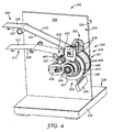
- FIGS. 4-9 illustrate a web handling system 300 according to one embodiment of the present disclosure.
- the web handling system 300 includes a curing section 322 and a web stretching section 324, both of which are coupled to and supported by a support 326.
- the support 326 includes a base 328 and a wall 330; however, it should be apparent to one of ordinary skill in the art that the support 326 can include any additional framework or other structures necessary to hold or provide support to the web handling system 300.
- the wall 330 separates the web handling system 300 into a front portion 332 and a rear portion 334.
- the front portion 332 of the web handling system 300 houses a web 301 and portions of the web handling system 300 that come into contact with the web 301.
- the rear portion 334 houses controllers, motors, or other devices (not shown) that drive, control and/or provide power to various portions of the web handling system 300.
- the wall 330 allows the web 301 and the portions of the web handling system 300 that contact the web 301 to be separated from any other devices or machinery that might produce debris or otherwise adversely affect the integrity of the web 301, as is well-known in the art.
- FIGS. 4-9 does not include a coating section, but it should be understood that the web handling system 300 can include or be used with a variety of upstream and downstream processes, including an upstream coating section in which a coating 306 is applied to the web 301, such that a coated web 304 is supplied to the web handling system 300.
- the curing section 322 of the web handling system 300 includes a UV radiation source 338 and any framework for supporting the UV radiation source (not shown). As mentioned above, the curing section 322 can include a variety of devices for curing the coating 306, and the UV radiation source 338 is shown by way of example only.
- the web stretching section 324 is substantially coincident with the curing section 322, such that the web 301 is stretched when the coating 306 is cured, and particularly, the web 301 is stretched during the portion of the curing process at which a strain is induced by curing the coating 306.
- the web stretching section 324 includes one web stretching assembly 340, which is described in greater detail below.
- the web stretching assembly 340 of the illustrated embodiment includes a tenter system 341.
- the tenter system 341 grips lateral ends 342 of the web 301 to stretch the web 301 in a cross-machine direction to induce a cross-machine-directional strain in the web 301.
- the web 301 is also stretched in the machine direction by applying web line tension to the web 301 to induce a machine-directional strain in the web 301 substantially simultaneously to inducing a cross-machine directional strain in the web 301.
- Many coatings 306 are relatively fluid, so the web 301 can be stretched without disturbing the coating 306.
- the coating 306 does not extend across the entire width of the web 301, such that the coating 306 is not applied to the lateral ends 342 of the web 301. This can facilitate gripping the lateral ends 342 of the web 301 and can avoid disturbing the coating 306 during the web stretching process.
- the web line tension can be applied to the web 301 in at least the web stretching section 324 of the web handling system 300, but it could be applied to the web 301 substantially throughout its path in the web handling system 300.
- the web line tension that is applied to the web 301 in the machine direction is sufficient to produce the desired machine direction strain in the web.
- the appropriate amount web line tension can depend on a number of factors, including the type of web used, but in some embodiments, the web line tension is at least about 3 pounds per linear inch (PLI; 525 N/m), particularly, at least about 5 PLI (875 N/m), and more particularly, at least about 10 PLI (1750 N/m).
- the web 301 can be stretched biaxially to induce a strain in the web 301 in both the machine direction and the cross-machine direction.
- the strain induced by the web stretching section 324 is designed to match any strain that will be induced in the web 301 when the coating 306 is cured in the curing section 322.
- the web stretching section 324 can apply one or both of machine-directional stress and cross-machine-directional stress to the web 301, depending on what strain is needed to reduce, match or reverse the strain induced by curing the coating 306.
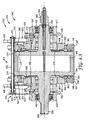
- the tenter system 341 includes a roller 344 (see FIGS. 7-8A ) and two endplates 346 over which the web 301 is moved during travel through the tenter system 341.
- the tenter system 341 further includes a shaft 348 to which the roller 344 and endplates 346 are coupled for rotation about axis A-A (see FIG. 6 ).
- the tenter system 341 further includes a belt transport assembly 350 and an endplate tilt assembly 352.
- the roller 344 is in the form of a substantially uniform cylinder and includes an outer circumferential surface 345
- each of the endplates 346 is in the form of a substantially uniform ring and includes an outer circumferential surface 347.
- the roller 344 and the endplates 346 all have substantially the same radius R (see FIGS. 5 and 8 ), and each endplate 346 is positioned laterally with respect to the roller 344, such that each endplate 346 is on an opposite lateral end of the roller 344 from one another.
- the tenter system 341 is laterally symmetric.
- One lateral side is described below for simplicity and clarity, but it should be understood that such description applies to both lateral sides of the tenter system 341.
- both lateral sides are described, but when one side is described, it should be assumed that the description applies equally to the other lateral side of the tenter system 341.
- a first (medial) circumferential groove 354 and a second (lateral) circumferential groove 356 are formed in the outer circumferential surface4 347 of the endplate 346.
- the first circumferential groove 354 is spaced a lateral distance from the second circumferential groove 356.
- Each of the first and second circumferential grooves 354, 356 is dimensioned to receive a belt 358.
- the lateral ends 342 of the web 301 are pinned between the belt 358 and the first circumferential groove 354, and the web 301 remains pinned between the belt 358 and the first circumferential groove 354 as it travels around a portion of the roller 344 and endplates 346.
- the endplate 346 is oriented at an angle with respect to the roller 344 by the endplate tilt assembly 352, which will be described in greater detail below.
- the endplate 346 is oriented at an angle (i.e., a non-perpendicular angle) with respect to the axis A-A of rotation.
- the endplate 346 is spaced a lateral distance from the end of the roller 344 and is substantially parallel to the end of the roller 344.
- the endplate 346 is substantially circular (i.e., has a substantially constant radius) and substantially flat, tilting the endplate 346 with respect to the roller 344 causes half of the endplate 346 to be positioned laterally further from the roller 344 and half of the endplate 346 to be positioned laterally closer to the roller 344.
- the endplate 346 includes a first point P 1 (see FIG. 5 ) at which it is spaced a maximal lateral distance from the roller 344, and a second point P 2 (see FIG. 5 ) diametrically opposite (i.e., 180 degrees from) the first point P 1 at which the endplate 346 is spaced a minimal lateral distance from the roller 344.
- the roller 344 is integrally formed with the shaft 348.
- the roller 344, the endplates 346 and the shaft 348 can be discrete parts that are rotatable together about the axis A-A.
- the endplate 346 includes an inner medial surface 374 that is coupled to an outer lateral surface 376 of the roller 344 via one or more flexure connectors 378 (see FIGS. 8-9 ).
- the flexure connectors 378 allow the endplate 346 to be moved or pivoted laterally outwardly from the roller 344 while remaining coupled to the roller 344 such that the endplate 346 rotates about the axis A-A with the roller 344 and the shaft 348.
- the embodiment illustrated in FIGS. 4-9 includes four arcuate flexure connectors 378, which are positioned circumferentially about the endplate 346 adjacent the medial surface 374 of the endplate 346 and the outer lateral surface 376 of the roller 344.
- Other numbers and shapes of flexure connectors 378 are possible and within the spirit and scope of the present disclosure.
- the endplate 346 is rotatable about the axis A-A about a ring bearing 380, which is positioned to rotatably isolate the endplate 346 from the endplate tilt assembly 352.
- the endplate tilt assembly 352 includes a ring 382 about which the endplate 346 rotates.
- the ring 382 includes two diametrically opposed recesses 384, which are each dimensioned to receive an insert 386.
- Each insert 386 includes a pin recess 388 that is dimensioned to receive a first end 391 of a pin 390, such that the ring 382 is pivotally movable about the pin 390, and particularly, about an axis B-B of rotation. As shown in FIG.
- the axis A-A is substantially perpendicular to the axis B-B.
- a second end 392 of each of the pins 390 is dimensioned to be received in a recess 394 of a collar 396.
- the collar 396 does not rotate, and is rotationally isolated from the shaft 348 by two ring bearings 398.
- the collar 396 is also rotationally isolated from the endplate 346 by the ring bearing 380.
- the collar 396 further includes an outer circumferential groove 397 to which other components of the tenter system 341 (e.g., components of the endplate tilt assembly 352) can be coupled.
- the collar 396, the ring 382, and the pins 390 are inhibited from rotation about axis A-A, as described below.
- the endplate tilt assembly 352 further includes a tilt actuator, or pivot actuator, 400.
- the tilt actuator 400 of the illustrated embodiment includes a tie rod 402 and two brackets 404.
- a first end 401 of the tie rod 402 is coupled to one bracket 404, and a second end 403 of the tie rod 402 is coupled to the other bracket 404.
- the brackets 404 are each coupled to an outer lateral surface 406 of the adjacent ring 382.
- Each bracket includes a proximal end 413 and distal end 414.
- the proximal end 413 is shaped and dimensioned to be received in the outer circumferential groove 397 of the adjacent collar 396.
- the proximal end 413 includes a medial projection 408 that is dimensioned to be received in an annular groove 410 defined in the outer lateral surface 406 of the ring 382.
- each bracket 404 extends radially outwardly from the ring 382. Distal ends 414 of the brackets 404 are connected by the tie rod 402. As the tie rod 402 is shortened (i.e., was the first end 401 and the second end 403 of the tie rod 402 are brought closer together), the distal ends 414 of the brackets 404 are moved closer together, which causes the ring 382 to pivot about the pins 390, and particularly, about the axis B-B.
- the endplate 346 which is coupled to the ring 382, in turn pivots about the pins 390, such that the endplate 346 is spaced a maximal lateral distance from the roller 344 at the first point P 1 , which is diametrically opposite the bracket 404 and tie rod 402.
- the second point P 2 (see FIG. 5 ) at which the endplate 346 is spaced a minimal lateral distance from the roller 344 is located along the same radial line as the tie rod 402 relative to the endplate 346.
- the tie rod 402 and the second point P 2 are positioned at approximately ten o'clock on the endplate 346 when viewed from the side (see FIG. 5 ), and the first point P 1 is positioned at approximately four o'clock on the endplate 346 when viewed from the side.
- the endplate tilt assembly 352 employs a tie rod 402 to cause the ring 382, and in turn the endplate 346, to pivot about the pins 390.
- Other devices and mechanisms can be used to tilt or pivot the endplate 346 relative to the roller 344, the shaft 348, and/or the axis of rotation A-A.
- an alternative endplate tilt assembly 352' includes a plurality of spherical roller bearings 418 that are coupled, either directly or indirectly, between the endplate 346 and a fixed (i.e., non-rotating) portion of the tenter system 341, such as the ring 382, as shown in FIG. 10 .
- the spherical roller bearings 418 allow the endplate 346 to rotate about the axis A-A and pivot laterally with respect to the ring 382, and in turn, to pivot laterally with respect to the roller 344 to a position in which the endplate 346 is oriented at an angle (i.e., a non-perpendicular angle) with respect to the axis A-A.
- an angle i.e., a non-perpendicular angle
- the tenter system 341 further includes a first mounting collar 420 and a second mounting collar 421.
- the first mounting collar 420 couples the remainder of the tenter system 341 to the wall 330, as shown in FIG. 6 .
- the second mounting collar 421 allows the web handling system 300 to be coupled to an outboard portion (not shown) of the support 326.
- the first and second mounting collars 420, 421 are each rotationally isolated from the shaft 348 by spherical roller bearings 422, and do not rotate.
- first and second flanges 423, 424 are coupled to the first and second mounting collars 420, 421, respectively.
- the first and second flanges 423, 424 are also coupled to the endplate tilt assembly 352 and allow the endplate tilt assembly 352 to be coupled to the support 326 for inhibition against rotation.
- the first flange 423 is coupled to the wall 330, and allows the endplate tilt assembly 352 to be coupled to the wall 330.
- the second flange 424 allows the endplate tilt assembly 352 to be coupled to an outboard portion of the support 326.
- the first flange 423 includes an extension 425 that is also coupled to the wall 330 and to the second end 403 of the rod 402 of the endplate tilt assembly 352.
- the first and second flanges 424 allow the endplate tilt assembly 352 to be coupled to the support 326, and particularly, allow the collar 396, the ring 382, and the pins 390 to be rotationally isolated from the endplate 346 and the shaft 348.
- a first end 339 of the shaft 348 extends through the wall 330 and allows motors or other driving means to be coupled to the tenter system 341, as shown in FIG. 6 .
- a rotary union 364 is coupled to a second end 349 of the shaft 348.
- the rotary union 364 is in fluid communication with a chamber 366 of the roller 344 via a lumen 368 of the shaft 348 (see FIGS. 8 and 8A ).
- a coolant e.g., water
- the illustrated rotary union 364 includes an inlet 370 and an outlet 372. Cooled coolant is directed into the chamber 366 via the lumen 368. The coolant receives heat from the roller 344 and is directed out of the chamber 366 and out of the outlet 372 of the rotary union 364 to be recooled by a cooling or refrigeration system (not shown).
- the lateral ends 342 of the web 301 are pinned between the belt 358 and the first circumferential groove 354 in the outer circumferential surface 347 of the endplate 346.
- the web 301 remains pinned between the belt 358 and the first circumferential groove 354 until a circumferential position at which the web 301 leaves the roller 344 and endplates 346 for downstream processes.
- the belt 358 needs to release the web 301 from being pinned between the belt 358 and the first circumferential groove 354. This can be accomplished in a variety of ways.
- One exemplary solution is to employ the belt transport assembly 350, which is illustrated in FIGS. 4-7 and described below.
- the belt transport assembly 350 is configured to continuously move the belt 358 about the endplate 346, while allowing the belt 358 to shift between the first and second circumferential grooves 354, 356 in the endplate 346.
- the first and second circumferential grooves 354, 356 are spaced a lateral distance apart such that when the belt 358 is positioned in the second circumferential groove 356, the belt 358 is not contacting the lateral end 342 of the web 301.
- the first and second circumferential grooves 354, 356 are positioned such that the ultimate lateral edge of the web 301 is located between the first and second circumferential grooves 354, 356 when the web 301 is moved about the roller 344 and endplates 346.
- allowing the belt 358 to shift between the first and second circumferential grooves 354, 356 allows the belt 358 to alternate, respectively, between a first position 360 in which the belt 358 is in contact with the lateral end 342 of the web 301 and a second position 362 in which the belt 358 is not in contact with the lateral end 342 of the web 301.
- the belt transport assembly 350 transports the belt 358 and "jumps" the belt 358 between the first circumferential groove 354 to the second circumferential groove 356.
- the belt transport assembly 350 illustrated in FIGS. 4-7 jumps the belt 358 from the first circumferential groove 354 to the second circumferential groove 356 at one point about the endplate 346, and jumps the belt 358 back to the first circumferential groove 354 at another point about the endplate 346.
- the belt transport assembly 350 can employ a variety of devices and mechanisms to accomplish the task of jumping the belt 358 between the first and second circumferential grooves 354, 356.
- the belt transport assembly 350 includes a first arm 426 and a second arm 428 (i.e., on either side of the tenter system 341) that are coupled to and extend radially outwardly from the collar 396, adjacent the endplate 346.
- the first arm 426 is positioned at about a twelve o'clock position (when viewed from the perspective of FIG. 5 ), and the second arm 428 is positioned at about an eight o'clock position.
- first arm 426 and the second arm 428 are separated by an angle of less than about 120 degrees and greater than about 90 degrees.
- Other arrangements and orientations of the first and second arms 426, 428 are possible, and can depend at least partially on where the web 301 enters the roller 344, which direction the web 301 is coming from, which direction the web 301 needs to exit the roller 344 for downstream processes, and how much stretching of the web 301 and curing of the coating 306 is needed, which can depend on a number of factors, including the type of web 301 and coating 306 used.
- the first arm 426 includes a first roller 430 in a first circumferential position, a second roller 432 spaced radially outwardly and positioned clockwise relative to the first roller 430, and a third roller 434 spaced radially inwardly and clockwise relative to the second roller 432.
- the first and third rollers 430, 434 are positioned such that they contact the outer circumferential surface 347 of the endplate 346.
- the second arm 428 includes a first roller 436, a second roller 438, and a third roller 440 arranged in a similar configuration as those of the first arm 426.
- Each of the second rollers 432, 438 is canted such that its axis of rotation is oriented at an angle with respect to the adjacent first and third rollers 430, 436 and 434, 440, respectively.
- the second roller 432, 438 can be canted at an angle of about 30 degrees with respect to the first and third rollers 430, 436 and 434, 440, respectively.
- Other angles of orientation can be used, and can be at least partially determined by the distance between the first and second circumferential grooves 354, 356, the size (i.e., thickness) of the belt 358, and the diameter of the rollers 432, 438.
- the first arm 426 and the second arm 428 accomplish opposite tasks.
- the first arm 426 is configured to move the belt 358 from its second position 362 in the second circumferential groove 354 to its first position 360 in the first circumferential groove 354.
- the second arm 428 is configured to move the belt 358 from its first position 360 in the first circumferential groove 352 to its second position 362 in the second circumferential groove 356.
- the first roller 430 of the first arm 426 is located adjacent the endplate 346 above the second circumferential groove 356, the second roller 432 of the first arm 426 is canted inwardly, and the third roller 434 is positioned inwardly (i.e., medially) with respect to the first roller 430, such that the third roller 434 is adjacent the endplate 346 above the first circumferential groove 354.
- first roller 436 of the second arm 428 is located adjacent the endplate 346 above the first circumferential groove 354, the second roller 438 is canted outwardly, and the third roller 440 is positioned outwardly (i.e., laterally) with respect to the first roller 436, such that the third roller 440 is adjacent the endplate 346 above the second circumferential groove 356.
- the belt 358 is in its second position 362 and positioned within the second circumferential groove 356 of the endplate 346. As such, the belt 358 is not in contact with the web 301 at this point.
- the belt 358 is directed under the first roller 430 of the first arm 426 of the belt transport assembly 350. After passing under the first roller 430, the belt 358 passes up to and over the second roller 432, which is grooved to inhibit the belt 358 from being pulled off of the second roller 432.
- the belt 358 By passing over the second roller 432, the belt 358 is removed from the endplate 346 and directed about 30 degrees inwardly (i.e., medially with respect to the roller 344 and endplate 346). The belt 358 then passes down to and under the third roller 434 and into the nip formed between the third roller 436 and the outer circumferential surface 347 of the endplate 346, such that the belt 358 is directed into the first circumferential groove 354. Positioning the belt 358 within the first circumferential groove 354 positions the belt 358 in its first position 360, in which the belt 358 is in contact with the lateral end 342 of the web 301.
- the belt 358 is then directed about the endplates 346, while remaining in contact with the web 301, to the second arm 428 of the belt transport assembly 350.
- the belt 358 is directed under the first roller 436 of the second arm 428 and then up to and over the second roller 438, which can be grooved, similar to the second roller 432 of the first arm 426.
- the belt 358 is removed from the endplate 346 and directed about 30 degrees outwardly (i.e., laterally with respect to the roller 344 and endplate 346).
- the belt 358 then passes down to and under the third roller 440 and into the nip formed between the third roller 440 and the outer circumferential surface 347 of the endplate 346, such that the belt 358 is directed into the second circumferential groove 356. After passing under the third roller 440, the belt 358 returns back into its second position 362, in which the belt 358 is not in contact with the web 301, and so on.
- the outer circumferential surface 347 of the endplate 346 can include one circumferential groove that is dimensioned to receive the belt 358.
- the belt 358 can be routed around one or more additional rollers or pulleys positioned adjacent the endplate 346 that define a belt track. In such embodiments, the belt 358 moves along the circumferential groove over a portion of the endplate 346 corresponding to the portion over which the web 301 should be stretched. The belt 358 is then removed from the circumferential groove at a point where the web 301 should no longer be stretched and is directed to the belt track. The belt 358 continues around the additional rollers or pulleys along the belt track until it is repositioned in the circumferential groove at the position where the web 301 should be pinned.
- the coated web 304 is directed from upstream processes to the web handling system 300, and particularly, to the web stretching section 324 and the curing section 322.
- the coated web 304 is moved toward the tenter system 341, and the web 301 contacts the roller 344 and the endplates 346 at about an eleven o'clock position (see FIG. 5 ).
- the web 301 contacts the roller 344 and endplates 346, the web 301 enters the nip formed between the first roller 430 of the first arm 426 of the belt transport assembly 350 and the outer circumferential surface 347 of the endplate 346.
- the ultimate lateral edge of the web 301 is positioned between the first and second circumferential grooves 354, 356 of the endplate 346, such that the web 301 is not yet in contact with the belt 358.
- the lateral ends 342 of the web 301 are pinned at about a twelve o'clock position between the belt 358 and the first circumferential groove 354 under the third roller 434 of the first arm 426 of the belt transport assembly 350.
- the endplate tilt assembly 352 of the illustrated embodiment is configured in the manner described above and illustrated in FIGS. 4-9 , the endplates 346 are tilted with respect to the roller 344 such that the endplates 346 have a maximal lateral spacing from the roller 344 at the first point P 1 (see FIG. 5 ). Due to the lateral symmetry of the tenter system 341, the endplates 346 are both directed laterally outwardly from the roller 344 at the first point P 1 .
- the lateral ends 342 of the web 301 remain gripped between the belt 358 and the first circumferential groove 354 in the endplates 346, and the web 301 is stretched in a cross-machine direction, which induces a strain (e.g., an elastic strain) in the web 301.
- Cross-machine directional stretching of the web 301 is indicated in FIGS. 4 and 6 by phantom lines drawn across the width of the coated web 304.
- the web 301 reaches a point of maximal cross-machine directional stain when it passes over the first point P 1 on the endplate 346. After passing the first point P 1 , the web 301 is still being stretched to some extent but has begun to rebound back to its original, unstretched state.
- the coated web 304 is directed into the curing section 322 of the web handling system 300.
- the UV radiation source 338 irradiates the coated web 304 with UV radiation, causing the coating 306 to begin to cure.
- the coating 306 can continue to cure as the coated web 304 is directed around the roller 344 and endplates 346.
- the coating 306 is shown schematically in FIG. 5 in its uncured state (identified by reference numeral 306) and its cured (or partially cured) state 306' (see also FIG. 7 ). Curing the coating 306 forms a multi-layer web 310 that comprises the cured coating 306' coupled to the web 301.
- the multi-layer web 310 is directed under the first roller 436 of the second arm 428 of the belt transport assembly 350 (in some embodiments, the coating may still be curing at this point).
- the belt 358 is directed out of the first circumferential groove 354 of the endplate 346, and the lateral ends 342 of the web 301 are released from being pinned between the belt 358 and the first circumferential groove 354. Accordingly, the lateral ends 342 of the web 301 are released from the belt 358 at about an eight o'clock position on the endplate 346.
- the web 301 will continue rebounding after it is released from the belt 358.
- the multi-layer web 310 having a desired curvature is then released from the roller 344 and endplates 346 at about a nine o'clock position and passed over a downstream roller 446 that is positioned to direct the resulting multi-layer web 310 away from the web stretching section 324 and the curing section 322 toward downstream processes.
- a web stretching section including a biaxial tenter systems similar to the tenter system shown in FIGS. 4-9 was mounted to a HIRANO MULTI COATERTM Model M-200 coating machine, commercially available from Hirano Tecseed Company, Ltd. of Nara, JP.
- a 10-inch (25.4 cm) wide roll of 0.56 mil (14 ⁇ m) thick polyethylene terephthalate (PET) film, commercially available from DuPont Teijin Films of Hopewell, VA was fed to the tenter system as depicted in FIG. 4 .
- An upstream coating section included a coating die generally of the type described in U.S. Patent No. 5,639,305 .
- a conventional pump was used to feed a coating fluid to the coating die.
- the coating composition was a photopolymerizable dispersion with solids consisting mainly of 51% by weight pentaerythritoltriacrylate ("SR-444" from Sartomer Company, Inc. of Exton, PA) and 37% by weight reaction product of colloidal silica ("Nalco 2327” from Nalco Company of Naperville, IL) and 3-trimethoxysilylpropyl methacrylate ("A174" from Momentive Performance Materials of Wilton, CT).
- Other solid additives in PETA were 8% by weight n,n-dimethylacrylamide ("NNDMA” from Sigma-Aldrich Company of St.
- the coating composition was prepared at 30 wt. % solids from a dispersion of approximately 50 wt. % solids in a 2-propanol diluent. Specifically, the coating composition was prepared according to column 10, lines 25-39 and Example 1 of US Patent No. 5,677,050 to Bilkadi, et. al.
- a curing section was provided adjacent to and substantially coincident with the web stretching section.
- the curing section included a UV radiation source, commercially available from Fusion UV System, Inc. of Gaithersburg, MD.
- the described coater was operated to advance the PET film at a line speed of 3 m/min.
- the coating die was adjusted to dispense a layer of the coating fluid that would cure to a 10- ⁇ m thick coating.
- the coating was cured by the curing section by the application of UV radiation.
- the tcntcring function was not engaged, and the web line tension was 10 lbs (44 N; i.e., 1 PLI (175 N/m) based on the 10-inch-wide (0.254-m-wide) web).
- a coating experiment was performed generally as described in Example 1, except that the tentering function of the tenter system was engaged to provide a strain of 0.9 % in the cross-machine direction, and a web line tension of 31 lbs (138 N; 3.1 PLI (543 N/m) based on the 10-inch-wide (0.254-m-wide) web) was used to provide a 0.9 % strain (0.009 in./in.) in the machine direction.
- the web was stretched in the machine direction and the cross-machine direction during curing of the coating, and particularly, during coating stress development.
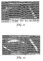
- the 2" inch (5 cm) disc was die cut from the sheet and allowed to take on its natural shape, it was observed that the disc lay substantially flat, as shown on the left-hand side of FIG. 11 .
- FIG. 13 is a graph of the curvature of the resulting multi-layers webs (ordinate) versus the biaxial strain (abscissa) that was induced by stretching during curing of the coating.
- a coating experiment was performed generally as described in Example 1, except that the coating was performed on a 0.92 mil (24 ⁇ m) thick roll of PET commercially available from DuPont Teijin Films of Hopewell, VA.
- the 2" inch (5 cm) disc was die cut from the sheet and allowed to take on its natural shape, it was observed that the disc curled upon itself into a tight cylinder of about a 5-mm radius, as shown on the right hand side of FIG. 12 .
- a coating experiment was performed generally as described in Example 3, except that the tentering function was engaged to provide a strain of 0.9 % in the cross-machine direction and a web line tension of 51 lbs (227 N; 5.1 PLI (894 N/m) based on the 10-inch-wide (0.254-m-wide) web) was used to provide a 0.9 % strain in the machine direction.
- a web line tension 51 lbs (227 N; 5.1 PLI (894 N/m) based on the 10-inch-wide (0.254-m-wide) web
Landscapes
- Engineering & Computer Science (AREA)
- Mechanical Engineering (AREA)
- Life Sciences & Earth Sciences (AREA)
- Wood Science & Technology (AREA)
- Chemical & Material Sciences (AREA)
- Health & Medical Sciences (AREA)
- Chemical Kinetics & Catalysis (AREA)
- Medicinal Chemistry (AREA)
- Polymers & Plastics (AREA)
- Organic Chemistry (AREA)
- Application Of Or Painting With Fluid Materials (AREA)
- Treatment Of Fiber Materials (AREA)
Claims (10)
- Verfahren zur Herstellung einer mehrschichtigen Bahn (20, 110, 310) mit einer gewünschten Krümmung, wobei das Verfahren Folgendes aufweist:Bereitstellen einer beschichteten Bahn (14, 104, 304), wobei die beschichtete Bahn eine Beschichtung (16, 106, 306) aufweist, die auf eine Bahn (11, 101,301) unbestimmter Länge aufgebracht ist,Härten der Beschichtung, um eine mehrschichtige Bahn (20, 110, 310) zu bilden, wobei die mehrschichtige Bahn eine durch das Härten der Beschichtung hervorgerufene Dehnung aufweist, undStrecken der Bahn während des Härtens der Beschichtung, um in der Bahn eine entgegengesetzte Dehnung hervorzurufen, die der durch das Härten hervorgerufenen Dehnung mindestens teilweise derart entgegenwirkt, dass die entstandene mehrschichtige Bahn eine gewünschte Krümmung aufweist, wobei die entgegengesetzte Dehnung kleiner als die Streckdehnung der Bahn ist,wobei das Strecken der Bahn Folgendes aufweist:Führen der Bahn über eine Rolle (344) und eine Endplatte (346), die dafür eingerichtet sind, sich um eine Rotationsachse zu drehen, wobei die Endplatte angrenzend an ein Ende der Rolle angebracht und in Bezug zur Rotationsachse in einem Winkel ausgerichtet ist, wobei die Endplatte (346) eine außen umlaufende Oberfläche (347) aufweist, undFesthalten eines Seitenendes (342) der Bahn derart zwischen einer in der außen umlaufenden Oberfläche (347) der Endplatte (348) gebildeten Rille (354, 356) und einem Riemen, der derart bemessen ist, dass er in einem Abschnitt der Rille aufgenommen wird, damit die Bahn quer zur Maschinenrichtung gestreckt wird, wenn sie über die Rolle und die Endplatte geführt wird, wobei sich die Rille um die Endplatte umlaufend erstreckt.
- Verwenden eines Bahnbearbeitungssystems (300) zur Herstellung einer mehrschichtigen Bahn mit einer gewünschten Krümmung, wobei das Bahnbearbeitungssystem Folgendes aufweist:einen Härtungsabschnitt (322), der dafür gestaltet ist, eine Beschichtung (16, 106, 306) zu härten, die auf eine Bahn (11, 101, 301) unbestimmter Länge aufgebracht ist, um eine mehrschichtige Bahn zu bilden, undeinen Bahnstreckabschnitt (324), der dafür gestaltet ist, die Bahn quer zur Maschinenrichtung zu strecken, um weniger als etwa 10 % Dehnung in der Bahn hervorzurufen, wobei sich der Bahnstreckabschnitt nahe des Härtungsabschnittes befindet und im Wesentlichen derart mit diesem übereinstimmt, dass die Bahn während des Härtens der Beschichtung gestreckt wird, wobei die Dehnung unter der Dehnungsgrenze der Bahn liegt.
- Bahnbearbeitungssystem (300) zur Herstellung einer mehrschichtigen Bahn mit einer gewünschten Krümmung, wobei das Bahnbearbeitungssystem Folgendes aufweist:einen Härtungsabschnitt (322), der dafür gestaltet ist, eine Beschichtung (16, 106, 306) zu härten, die auf eine Bahn (11, 101, 301) unbestimmter Länge aufgebracht ist, um eine mehrschichtige Bahn zu bilden, undeinen Bahnstreckabschnitt (324), der dafür gestaltet ist, die Bahn zu strecken, um weniger als etwa 10 % Dehnung in der Bahn hervorzurufen, wobei sich der Bahnstreckabschnitt (324) nahe des Härtungsabschnittes (322) befindet und im Wesentlichen derart mit diesem übereinstimmt, dass die Bahn während des Härtens der Beschichtung gestreckt wird, wobei die Dehnung unter der Dehnungsgrenze der Bahn liegt, wobei der Bahnstreckabschnitt (324) ein Spannrahmensystem (341) aufweist, das Folgendes aufweist:eine Rolle (344), die um eine Rotationsachse drehbar ist,eine Endplatte (346), die mit der Rolle (344) gekoppelt und um die Rotationsachse drehbar ist, wobei die Endplatte in Bezug zur Rotationsachse in einem nicht rechten Winkel ausgerichtet ist, wobei die Endplatte eine außen umlaufende Oberfläche (347) aufweist, die in Kontakt mit der Bahn angeordnet ist,eine Rille (354, 356), die in der außen umlaufenden Oberfläche der Endplatte definiert ist, wobei sich die Rille umlaufend erstreckt, undeinen Riemen (358), der derart bemessen ist, dass er in der Rille aufgenommen wird, so dass ein Seitenende der Bahn zwischen der Rille und dem Riemen festgehalten wird, wenn die Bahn durch den Bahndehnungsabschnitt bewegt wird.
- Bahnbearbeitungssystem nach Anspruch 3, ferner eine Riementransportanordnung (350) aufweisend, die dafür eingerichtet ist, den Riemen (358) derart in die und aus der Rille zu bewegen, dass der Riemen über einen Abschnitt der Endplatte in der Rille angeordnet ist, in welchem die Bahn gestreckt wird.
- Bahnbearbeitungssystem nach Anspruch 3, wobei die Rille eine erste Rille (354) ist und wobei das Bahnbearbeitungssystem ferner Folgendes aufweist:eine zweite Rille (356), die in der außen umlaufenden Oberfläche der Endplatte definiert ist, wobei sich die zweite Rille umlaufend erstreckt und von der ersten Rille (354) seitlich beabstandet ist, undeine Riementransportanordnung (350), die dafür gestaltet ist, den Riemen (358) zwischen einer ersten Position, in welcher der Riemen in der ersten Rille aufgenommen ist, und einer zweiten Position, in welcher der Riemen in der zweiten Rille aufgenommen ist, zu verschieben.
- Bahnbearbeitungssystem nach Anspruch 5, wobei die Riementransportanordnung (350) Folgendes aufweist:eine erste Rolle (430), die angrenzend an die außen umlaufende Oberfläche der Endplatte über der ersten umlaufenden Rille angeordnet ist,eine zweite Rolle (432), die entfernt von der außen umlaufenden Oberfläche der Endplatte angeordnet ist, undeine dritte Rolle (434), die angrenzend an die außen umlaufende Oberfläche der Endplatte über der zweiten umlaufenden Rille angeordnet ist,wobei die zweite Rolle (432) in Bezug zur ersten und zur dritten Rolle derart in einem Winkel ausgerichtet ist, dass der Riemen zwischen der ersten Rille und der zweiten Rille verschoben wird, wenn der Riemen über die zweite Rolle läuft.
- Bahnbearbeitungssystem nach einem der Ansprüche 3 bis 6, wobei das Bahnbearbeitungssystem ferner eine Endplattenneigeanordnung (352) aufweist, die dafür gestaltet ist, die Endplatte in Bezug zur Rotationsachse in einem nicht rechten Winkel auszurichten.
- Bahnbearbeitungssystem nach Anspruch 7, wobei die Endplattenneigeanordnung (352) Folgendes aufweist:einen Stift, der derart mit der Endplatte gekoppelt und drehbar von der Endplatte isoliert ist, wobei der Stift eine zweite Rotationsachse aufweist, die im Wesentlichen senkrecht zur Rotationsachse der Endplatte ausgerichtet ist, dass die Endplatte, wenn sie um die zweite Rotationsachse geschwenkt wird, in Bezug zu ihrer Rotationsachse in einem nicht rechten Winkel ausgerichtet wird, undeinen Neigeauslöser, der dafür gestaltet ist, das Schwenken der Endplatte um die zweite Rotationsachse auszulösen.
- Bahnbearbeitungssystem nach Anspruch 8, wobei die Endplatte eine erste Endplatte ist, wobei das Bahnbearbeitungssystem ferner eine zweite Endplatte aufweist, die angrenzend an ein Seitenende der Rolle gegenüber der ersten Endplatte angeordnet ist, und wobei der Neigeauslöser Folgendes aufweist:eine Zugstange mit einem ersten Ende, das an die erste Endplatte gekoppelt ist, und einem zweiten Ende, das an die zweite Endplatte gekoppelt ist, wobei die Zugstange derart für eine Längenänderung eingerichtet ist, dass beim Verändern der Zugstangenlänge der Abschnitt der ersten Endplatte, der an das erste Ende der Zugstange gekoppelt ist, und der Abschnitt der zweiten Endplatte, der an das zweite Ende der Zugstange gekoppelt ist, in Bezug zueinander bewegt werden.
- Bahnbearbeitungssystem nach Anspruch 7, wobei die Endplattenneigeanordnung Folgendes aufweist:einen Ring, der an die Endplatte gekoppelt ist, undmehrere Tonnenrollenlager, die zwischen dem Ring und der Endplatte angeordnet sind, wobei die Tonnenrollenlager derart ausgerichtet sind, dass sie das Drehen der Endplatte um den Ring um die Rotationsachse und das seitliche Schwenken in Bezug zum Ring ermöglichen.
Applications Claiming Priority (3)
| Application Number | Priority Date | Filing Date | Title |
|---|---|---|---|
| US82736806P | 2006-09-28 | 2006-09-28 | |
| US82737406P | 2006-09-28 | 2006-09-28 | |
| PCT/US2007/079492 WO2008039822A1 (en) | 2006-09-28 | 2007-09-26 | System and method for controlling curl in multi-layer webs |
Publications (2)
| Publication Number | Publication Date |
|---|---|
| EP2089458A1 EP2089458A1 (de) | 2009-08-19 |
| EP2089458B1 true EP2089458B1 (de) | 2011-09-21 |
Family
ID=38962061
Family Applications (1)
| Application Number | Title | Priority Date | Filing Date |
|---|---|---|---|
| EP07843204A Not-in-force EP2089458B1 (de) | 2006-09-28 | 2007-09-26 | Verfahren, system und dessen verwendung zur bekämpfung der rollneigung bei mehrschichtigen bahnen |
Country Status (4)
| Country | Link |
|---|---|
| US (2) | US8647556B2 (de) |
| EP (1) | EP2089458B1 (de) |
| AT (1) | ATE525422T1 (de) |
| WO (1) | WO2008039822A1 (de) |
Families Citing this family (14)
| Publication number | Priority date | Publication date | Assignee | Title |
|---|---|---|---|---|
| US7384586B2 (en) | 2004-03-23 | 2008-06-10 | 3M Innovative Properties Company | Method for flexing a web |
| US8871298B2 (en) | 2006-02-08 | 2014-10-28 | 3M Innovative Properties Company | Method for manufacturing on a film substrate at a temperature above its glass transition |
| EP2089458B1 (de) | 2006-09-28 | 2011-09-21 | 3M Innovative Properties Company | Verfahren, system und dessen verwendung zur bekämpfung der rollneigung bei mehrschichtigen bahnen |
| US7998534B2 (en) | 2006-09-28 | 2011-08-16 | 3M Innovative Properties Company | System and method for controlling curl in multi-layer webs |
| JP4519184B2 (ja) * | 2008-07-08 | 2010-08-04 | 欧文印刷株式会社 | 筆記用紙、及び筆記用紙の製造方法 |
| US20130216728A1 (en) * | 2012-02-16 | 2013-08-22 | Christopher Hurren | Continuous Low Vacuum Coating Apparatus |
| WO2016106043A1 (en) * | 2014-12-23 | 2016-06-30 | 3M Innovative Properties Company | Edge contact substrate transport method and apparatus |
| US11633905B2 (en) * | 2016-06-15 | 2023-04-25 | Flooring Industries Limited, Sarl | Long decorative material with embossing in register with pattern and rolling method and device therefor |
| CN105904822A (zh) * | 2016-06-15 | 2016-08-31 | 朱彩琴 | 压纹与花纹重合的长装饰材料及滚压方法和设备 |
| CN112172298A (zh) * | 2016-06-15 | 2021-01-05 | 浙江天振科技股份有限公司 | 压纹与花纹重合的长塑料层及滚压方法和设备 |
| US11633904B2 (en) * | 2016-06-15 | 2023-04-25 | Flooring Industries Limited, Sarl | Long plastic layer with embossing in register with pattern and rolling method and device therefor |
| CN107936276B (zh) * | 2017-12-14 | 2020-11-27 | 电子科技大学 | 基于流延及拉伸复合工艺的热释电聚合物薄膜制备方法 |
| CN110644727A (zh) | 2019-09-25 | 2020-01-03 | 浙江永裕竹业股份有限公司 | 一种在线同步对花共挤spc地板及其生产工艺 |
| CN116715068B (zh) * | 2023-06-27 | 2025-10-14 | 宜兴博雅新材料科技有限公司 | 一种多孔淀粉活性包装膜生产用收卷系统及方法 |
Citations (1)
| Publication number | Priority date | Publication date | Assignee | Title |
|---|---|---|---|---|
| WO2007110484A1 (en) * | 2006-03-28 | 2007-10-04 | Conenor Oy | Transverse stretching device |
Family Cites Families (190)
| Publication number | Priority date | Publication date | Assignee | Title |
|---|---|---|---|---|
| USRE16384E (en) | 1926-07-13 | Gaxxhdxbxhg | ||
| US2141318A (en) | 1938-12-27 | Rubber container manufacture | ||
| US478255A (en) | 1892-07-05 | Iftrls peters co | ||
| US236068A (en) | 1880-12-28 | Machine for winding dry enameled paper | ||
| US751527A (en) | 1904-02-09 | Apparatus for dividing | ||
| US273040A (en) | 1883-02-27 | Feedeeick h | ||
| US16384A (en) | 1857-01-13 | Improvement in locomotive-lamps | ||
| US1469875A (en) | 1923-10-09 | Leander philip beaukegard | ||
| US751227A (en) * | 1904-02-02 | Electric cut-out | ||
| US754797A (en) | 1903-09-24 | 1904-03-15 | Joseph H Ostrander | Felt-spreader. |
| US1167036A (en) | 1913-01-15 | 1916-01-04 | Charles Tagliabue Mfg Co | Thermostatic regulation for heated rollers. |
| US1191297A (en) | 1915-05-24 | 1916-07-18 | Flintkote Mfg Company | Machine for punching roof material. |
| US1238742A (en) | 1916-01-31 | 1917-09-04 | Ind Service And Equipment Company | Machine for stretching felt. |
| US1288643A (en) | 1917-08-22 | 1918-12-24 | Charles W Mayer | Stretching device for web-carrying rolls. |
| US1432832A (en) | 1920-05-24 | 1922-10-24 | Bluford W Brockett | Apron control |
| US1481866A (en) | 1921-11-10 | 1924-01-29 | Penn Rubber Products Corp | Method of and apparatus for covering cores |
| US1691023A (en) | 1925-12-30 | 1928-11-06 | Glen M Dye | Print-flattening device |
| US1654946A (en) | 1927-05-12 | 1928-01-03 | Charles M Sinks | Automatic paper-straightening attachment for adding machines |
| US1792596A (en) | 1928-09-08 | 1931-02-17 | Delphos Bending Company | Dry-wood-bending machine |
| US2070505A (en) | 1929-10-24 | 1937-02-09 | Charles J Beck | Decurling device |
| US1891782A (en) | 1929-12-09 | 1932-12-20 | Antcne Wayne Julien | Laundry flat piece spreader |
| US1880451A (en) | 1930-02-15 | 1932-10-04 | Eastman Kodak Co | Method for flattening prints |
| US2184744A (en) | 1933-04-29 | 1939-12-26 | Tri State Cap & Cap Machinery | Reeling mechanism |
| US2028700A (en) | 1934-06-20 | 1936-01-21 | All Steel Products Mfg Company | Tractor mounted winch with drive transmission |
| US2137887A (en) | 1934-07-14 | 1938-11-22 | Charles W Abbott | Method and apparatus for conduit construction |
| US2066872A (en) | 1934-10-09 | 1937-01-05 | Adams Gilbert Edward | Control system for strip mills and the like |
| US2037825A (en) | 1934-11-22 | 1936-04-21 | Ivers Lee Co | Package indicia means |
| GB456832A (en) * | 1935-02-11 | 1935-08-14 | Kodak Ltd | Improvements in or relating to cellulose organic derivative sheeting |
| US2027564A (en) | 1935-05-01 | 1936-01-14 | Stein Jacob | Rolling machine |
| US2152101A (en) | 1935-10-28 | 1939-03-28 | Robert P Scherer | Method and apparatus for making capsules by submerged filling action |
| US2334022A (en) | 1937-04-22 | 1943-11-09 | Henry D Minich | Rubber hydrohalide film |
| US2259362A (en) | 1940-03-14 | 1941-10-14 | Wingfoot Corp | Laminating and stretching |
| US2370811A (en) | 1940-06-28 | 1945-03-06 | Warren S D Co | Conditioning and finishing absorbent webs |
| US2307817A (en) | 1940-09-26 | 1943-01-12 | Du Pont | Polymeric product and process |
| US2398822A (en) | 1940-10-28 | 1946-04-23 | Nat Automotive Fibres Inc | Tension device for sheet material |
| US2403482A (en) | 1941-07-02 | 1946-07-09 | William S Cloud | Method and apparatus for wrapping articles |
| US2411774A (en) | 1941-07-15 | 1946-11-26 | Constance D Gundelfinger | Method and apparatus for manufacture of continuous filament and like structures |
| US2348162A (en) | 1941-08-25 | 1944-05-02 | Champion Paper & Fibre Co | Web spreader |
| US2339070A (en) | 1941-10-24 | 1944-01-11 | Smithe Machine Co Inc F L | Sheet decurling apparatus |
| US2293178A (en) | 1942-01-09 | 1942-08-18 | Cameron Machine Co | Art of severing thermoplastic webs |
| US2373040A (en) | 1942-03-28 | 1945-04-03 | Charles Bruning Co Inc | Combined printing and developing machine |
| US2335190A (en) | 1942-07-29 | 1943-11-23 | Henry D Minich | Stretched laminated product and process for making it |
| US2412187A (en) | 1943-08-17 | 1946-12-03 | Plax Corp | Process and apparatus for producing continuous sheet of biaxially oriented organic polymer |
| US2434111A (en) | 1944-02-24 | 1948-01-06 | Us Rubber Co | Method of manufacturing elastic fabrics |
| US2468697A (en) | 1944-06-01 | 1949-04-26 | Plax Corp | Method of deep drawing organic plastic sheets |
| US2547836A (en) | 1945-11-06 | 1951-04-03 | Fred B Pfeiffer | Apparatus for working sheet material |
| US2454999A (en) | 1946-05-23 | 1948-11-30 | Bendix Westinghouse Automotive | Combined brake and steering mechanism |
| US2531619A (en) | 1946-06-28 | 1950-11-28 | Beech Nut Packing Co | Machine for decurling labels |
| US2490781A (en) | 1946-08-22 | 1949-12-13 | William S Cloud | Method and apparatus for preparing and utilizing sheet material for packaging purposes |
| US2597877A (en) | 1946-09-04 | 1952-05-27 | Interchem Corp | Web handling device |
| US2559365A (en) | 1946-10-02 | 1951-07-03 | Earl F Middleton | Apparatus for reforming thermoplastic sheets |
| US2505146A (en) | 1946-12-14 | 1950-04-25 | Polaroid Corp | Process and apparatus for stretching continuous sheet materials |
| US2559705A (en) | 1947-07-08 | 1951-07-10 | Gustave W Borkland | Apparatus for drawing thermoplastic sheets |
| US2545868A (en) | 1947-10-11 | 1951-03-20 | Plax Corp | Method of and apparatus for manufacturing plastic sheets |
| US2483339A (en) | 1948-01-06 | 1949-09-27 | Gardner Ind Associates Inc | Apparatus for laterally stretching continuous sheets |
| US2660218A (en) | 1948-04-02 | 1953-11-24 | Gen Mills Inc | Welding apparatus |
| US2618012A (en) | 1948-05-14 | 1952-11-18 | American Viscose Corp | Method and apparatus for two-way stretching a continuous sheet |
| US2600295A (en) | 1948-12-04 | 1952-06-10 | Universal Match Corp | Photoengraving equipment |
| US2540986A (en) | 1949-08-01 | 1951-02-06 | Dow Chemical Co | Apparatus for preshrinking crystalline vinylidene chloride copolymer film |
| US2578899A (en) | 1949-10-22 | 1951-12-18 | Du Pont | Superstretching polyester structures |
| US2582165A (en) | 1950-04-05 | 1952-01-08 | Milprint Inc | Expansible tube tensilizing apparatus |
| US2574200A (en) * | 1950-05-23 | 1951-11-06 | Us Rubber Co | Method of making stretchable woven fabrics |
| US2702406A (en) | 1950-12-13 | 1955-02-22 | Energized Materials Corp | Apparatus for stretching sheet material |
| US2658432A (en) | 1951-02-01 | 1953-11-10 | John R Baumgartner | Paper decurling apparatus |
| US2976924A (en) | 1951-12-29 | 1961-03-28 | Black Clawson Co | Paper machinery |
| US2745134A (en) | 1952-05-24 | 1956-05-15 | Boston Woven Hose & Rubber Co | Apparatus for tensioning strip material |
| US2698982A (en) | 1952-09-10 | 1955-01-11 | Deering Milliken Res Trust | Control system for web handling machines |
| US2737089A (en) | 1953-10-21 | 1956-03-06 | John R Baumgartner | Apparatus for decurling a web |
| US2893053A (en) | 1955-06-29 | 1959-07-07 | E G Staude Mfg Company Inc | Decurling apparatus |
| US2918891A (en) | 1957-11-15 | 1959-12-29 | Klabunde Otto | Boat reciprocating paddle device |
| US2918897A (en) | 1958-07-28 | 1959-12-29 | Mercury Engineering Corp | Apparatus for decurling a web |
| US3215558A (en) * | 1959-02-16 | 1965-11-02 | Edward E Dascher | Method of coating metal foils with a polymerizable resinous coating |
| US3076492A (en) | 1959-10-30 | 1963-02-05 | Standard Packaging Corp | Apparatus for removing the curl from sheets |
| US3044228A (en) | 1960-04-22 | 1962-07-17 | Kimberly Clark Co | Cellulosic product and method for making same |
| BE673668A (de) * | 1964-12-28 | |||
| US3344493A (en) | 1965-02-19 | 1967-10-03 | Henry E Telgheider | Spreader roll |
| US3373288A (en) | 1965-08-26 | 1968-03-12 | Web Press Eng Inc | Photosensitive web shifting apparatus |
| US3366298A (en) | 1965-11-22 | 1968-01-30 | Procter & Gamble | Method and apparatus for web tension control |
| DE1685288B1 (de) * | 1967-04-08 | 1972-05-31 | Franz Fesl | Ski-bzw. Bergstiefel mit einem spannbaren Stuetzteil fuer das Fusslaengsgewoelbe |
| GB1205679A (en) | 1967-10-21 | 1970-09-16 | Ricoh Kk | Improvements in and relating to apparatus for handling strip material |
| US3482343A (en) | 1968-01-22 | 1969-12-09 | Kaino J Hamu | Frame for stressing sheet material |
| US3510036A (en) | 1968-03-29 | 1970-05-05 | Bobst Champlain Inc | Inserter and splicer with register control for a reprinted web |
| US3498878A (en) | 1968-05-29 | 1970-03-03 | Westvaco Corp | Magnetic curl breaker |
| US3567093A (en) | 1969-06-03 | 1971-03-02 | Michigan Oven Co | Fluid cushion turning roll for moving web |
| US3774831A (en) | 1969-06-26 | 1973-11-27 | Steel Corp | Steering roll assembly for continuous strip mill |
| US3604652A (en) | 1969-07-02 | 1971-09-14 | Addressograph Multigraph | Roll sheeter for printing machine |
| GB1373627A (en) | 1970-12-11 | 1974-11-13 | Ici Ltd | Coated films |
| GB1384381A (en) | 1971-03-27 | 1975-02-19 | Masson Scott Thrissell Eng Ltd | Curl corrector apparatus |
| GB1333663A (en) | 1971-04-16 | 1973-10-10 | Ilford Ltd | Photographic silver halide material |
| BE795702A (fr) | 1972-02-22 | 1973-06-18 | Royon Rene | Dispositif de reglage pour l'enroulement et le deroulement de materiaux a carreaux |
| US3724732A (en) | 1972-03-01 | 1973-04-03 | Rockford Servo Corp | Web sensing and guiding apparatus |
| US3890547A (en) | 1972-03-31 | 1975-06-17 | Norman Keck | Speed control device |
| US3854441A (en) | 1972-06-02 | 1974-12-17 | Bolton Emerson | Apparatus for applying barrier coating substances to sheet materials |
| US3976528A (en) | 1972-06-05 | 1976-08-24 | Cadillac Products, Inc. | Laminating method |
| US3833973A (en) * | 1972-06-16 | 1974-09-10 | Kimberly Clark Co | Simultaneous continuous biaxial web stretcher |
| US3913729A (en) | 1972-08-11 | 1975-10-21 | Cambridge Wire Cloth | Belt aligner |
| US3939025A (en) | 1972-08-18 | 1976-02-17 | E. I. Dupont De Nemours & Co. | Method of making a polyethylene terephthalate laminate |
| US4060236A (en) | 1973-05-10 | 1977-11-29 | Carstedt Howard B | Automatic sheet decurler |
| CH611435A5 (de) | 1974-06-05 | 1979-05-31 | Ciba Geigy Ag | |
| US3974952A (en) | 1974-09-10 | 1976-08-17 | Eastman Kodak Company | Web tracking apparatus |
| US4141735A (en) | 1975-03-31 | 1979-02-27 | Eastman Kodak Company | Process for reducing core-set curling tendency and core-set curl of polymeric film elements |
| JPS51127988A (en) | 1975-04-30 | 1976-11-08 | Ishikawajima Harima Heavy Ind Co Ltd | Tension control device having looper and this looper |
| US4002047A (en) | 1975-07-07 | 1977-01-11 | Baldwin-Gegenheimer Corporation | Sheet material decurling apparatus |
| US4013284A (en) | 1975-10-14 | 1977-03-22 | Eastern Graphic Products, Inc. | Decurler device |
| US4187113A (en) | 1975-11-05 | 1980-02-05 | Imperial Chemical Industries Limited | Voided films of polyester with polyolefin particles |
| NO139293C (no) | 1976-02-13 | 1979-02-07 | Elopak As | Kartonglaminat for bruk i beholdere for matvarer, saerlig flytende matvarer, og fremgangsmaate til fremstilling av et slikt kartonglaminat |
| US4069081A (en) | 1976-08-04 | 1978-01-17 | Sealtran Corporation | Method for protective film lamination with curl control |
| US4069959A (en) | 1976-10-27 | 1978-01-24 | Butler Automatic, Inc. | Web guide apparatus |
| DE2649051C2 (de) | 1976-10-28 | 1979-01-04 | Roland Offsetmaschinenfabrik Faber & Schleicher Ag, 6050 Offenbach | Vorrichtung zum Glätten von Bogen mittels Saugluft |
| DE2648986B1 (de) | 1976-10-28 | 1978-04-13 | Roland Offsetmaschf | Bogenglaetter an Druckmaschinen |
| US4182472A (en) | 1978-07-13 | 1980-01-08 | W. R. Grace & Co. | Contactless turning guide for running webs |
| DE2953637A1 (en) * | 1979-04-17 | 1982-01-28 | A Horike | Abrasion-resistant laminate film |
| JPS55156840A (en) | 1979-05-25 | 1980-12-06 | Olympus Optical Co Ltd | Specimen detector |
| DE3008775C2 (de) | 1980-03-07 | 1984-03-22 | Erhardt & Leimer Kg, 8900 Augsburg | Bahnlaufregelvorrichtung |
| US4300891A (en) | 1980-03-27 | 1981-11-17 | Bemiss Robert P | Apparatus for decurling a continuous web |
| US4322802A (en) | 1980-04-10 | 1982-03-30 | Lewis Jr Clarence A | Control apparatus for adjusting the position of a workpiece |
| US4360356A (en) | 1980-10-15 | 1982-11-23 | The Standard Register Company | Decurler apparatus |
| US4457254A (en) * | 1981-02-19 | 1984-07-03 | Mobil Oil Corporation | Film coating and biaxial orienting apparatus |
| US4389455A (en) | 1981-08-21 | 1983-06-21 | Fuji Photo Film Co., Ltd. | Photographic resin coated paper |
| DE3268297D1 (en) | 1981-09-25 | 1986-02-13 | Nissan Motor | Optical weft sensor for a loom |
| JPS5862080A (ja) | 1981-10-09 | 1983-04-13 | Canon Inc | プリンタ−の紙送り装置 |
| JPS6044310A (ja) | 1983-08-23 | 1985-03-09 | Inoue Mtp Co Ltd | 装飾用モ−ルの製造方法 |
| JPS6053949A (ja) | 1983-09-05 | 1985-03-28 | Fuji Photo Film Co Ltd | 写真印画紙の製法 |
| JPS60158028A (ja) | 1984-01-17 | 1985-08-19 | 冨士シ−ル工業株式会社 | ラベルの装着方法および装着装置 |
| US4539072A (en) | 1984-01-31 | 1985-09-03 | Beloit Corporation | Curl neutralizer |
| US4598849A (en) | 1984-03-23 | 1986-07-08 | Beloit Corporation | Web guiding and decurling apparatus |
| NZ211704A (en) | 1984-04-16 | 1987-07-31 | Tetra Pak Int | Laminated packaging material containing aluminium foil and manufacture thereof |
| US5290672A (en) | 1984-11-24 | 1994-03-01 | The Wiggins Teape Group Limited | Base paper for photographic prints |
| US4685230A (en) | 1986-06-20 | 1987-08-11 | Mason Iii William H | Adjustable biaxial stretcher |
| JPS63171755A (ja) | 1987-01-08 | 1988-07-15 | Canon Inc | シ−ト材巻きぐせ除去装置 |
| JPH0745181B2 (ja) | 1987-04-01 | 1995-05-17 | 富士写真フイルム株式会社 | ラミネ−ト物の製造方法 |
| JPH01285557A (ja) | 1988-05-10 | 1989-11-16 | Kobayashi Seisakusho:Kk | シートカール矯正装置 |
| US4952281A (en) | 1988-05-10 | 1990-08-28 | Kobayashi Engineering Works, Ltd. | Sheet curls reformer |
| US4862565A (en) | 1988-05-10 | 1989-09-05 | Damour Lawrence R | Spreader roll for wrinkle-free traveling web |
| US4925520A (en) | 1988-08-11 | 1990-05-15 | Curt G. Joa, Inc. | Apparatus for applying an elastic waistband transversely of a longitudinally moving web |
| US5043036A (en) | 1990-03-30 | 1991-08-27 | Minnesota Mining And Manufacturing Company | Width stretching device |
| DE69123511T2 (de) | 1990-08-23 | 1997-04-03 | Nippon Petrochemicals Co Ltd | Streckmaschine |
| JPH04121355A (ja) | 1990-09-12 | 1992-04-22 | Fuji Photo Film Co Ltd | フイルムの巻癖除去装置 |
| US5244861A (en) | 1992-01-17 | 1993-09-14 | Eastman Kodak Company | Receiving element for use in thermal dye transfer |
| EP0568268A2 (de) | 1992-04-27 | 1993-11-03 | Konica Corporation | Träger für fotografisches Material |
| US5536561A (en) * | 1993-03-23 | 1996-07-16 | Rexham Graphics Inc. | Straight webs and process of making |
| US5466519A (en) | 1993-04-28 | 1995-11-14 | Fuji Photo Film Co., Ltd. | Support for a photographic printing paper and a manufacturing process therefor |
| EP0658505B1 (de) | 1993-12-16 | 1999-11-10 | Eastman Kodak Company | Berührungsfreier Saugkasten und Verfahren zu dessen Betrieb |
| CA2125807A1 (en) | 1994-03-14 | 1995-09-15 | Edward Heerman Ruscher | Apparatus and method for stretching an elastomeric material in a cross machine direction |
| US5517737A (en) | 1994-06-06 | 1996-05-21 | The Procter & Gamble Company | Apparatus for continuously stretching or continuously releasing stretching forces from a web using two pairs of opposing non-planar belts |
| KR0162706B1 (ko) | 1994-06-20 | 1998-12-01 | 사이카와 겐조오 | 규제된 신축성 복합체 |
| US5967394A (en) | 1994-11-04 | 1999-10-19 | Roll Systems, Inc. | Method and apparatus for pinless feeding of web to a utilization device |
| KR19980702975A (ko) | 1995-03-15 | 1998-09-05 | 애브리데니슨코포레이션 | 제어된 정전기력을 가진 웹 이송기 및 그 방법 |
| US5677050A (en) | 1995-05-19 | 1997-10-14 | Minnesota Mining And Manufacturing Company | Retroreflective sheeting having an abrasion resistant ceramer coating |
| US5738907A (en) * | 1995-08-04 | 1998-04-14 | Eltech Systems Corporation | Conductive metal porous sheet production |
| JP3679485B2 (ja) | 1996-01-17 | 2005-08-03 | 富士写真フイルム株式会社 | ウエブのカール測定方法および装置、カール修正方法および装置 |
| GB9604241D0 (en) | 1996-02-28 | 1996-05-01 | Rockwool Int | Production of a lapped product from a web, and apparatus for this |
| IT1285604B1 (it) | 1996-03-12 | 1998-06-18 | Gd Spa | Metodo ed unita' per l'alimentazione in continuo di un materiale in nastro ad una macchina utilizzatrice |
| CA2214486C (en) * | 1996-09-04 | 2006-06-06 | Consolidated Papers, Inc. | Method and apparatus for minimizing web-fluting in heat-set, web-offset printing presses |
| US5853965A (en) | 1997-05-23 | 1998-12-29 | Eastman Kodak Company | Photographic element with bonding layer on oriented sheet |
| US5866282A (en) | 1997-05-23 | 1999-02-02 | Eastman Kodak Company | Composite photographic material with laminated biaxially oriented polyolefin sheets |
| US5888643A (en) | 1997-05-23 | 1999-03-30 | Eastman Kodak Company | Controlling bending stiffness in photographic paper |
| US5874205A (en) | 1997-05-23 | 1999-02-23 | Eastman Kodak Company | Photographic element with indicia on oriented polymer back sheet |
| AU8624598A (en) | 1997-06-10 | 1998-12-30 | Rockwool International A/S | Process and apparatus for transporting a web |
| US6362020B1 (en) | 1998-01-30 | 2002-03-26 | Canon Kabushiki Kaisha | Process of forming deposited film, process of producing semiconductor element substrate, and process of producing photovoltaic element |
| DE19808518C1 (de) | 1998-02-27 | 1999-08-05 | Rockwool Mineralwolle | Verfahren und Vorrichtung zur Beschichtung und/oder Imprägnierung von Mineralwolleprodukten |
| US6489015B1 (en) | 1998-11-17 | 2002-12-03 | Dai Nippon Printing Co., Ltd. | Hardcoat film and antireflection film |
| US6273984B1 (en) | 1998-11-20 | 2001-08-14 | Eastman Kodak Company | Lamination with curl control |
| US6030742A (en) | 1998-11-23 | 2000-02-29 | Eastman Kodak Company | Superior photographic elements including biaxially oriented polyolefin sheets |
| JP2000168045A (ja) | 1998-12-02 | 2000-06-20 | Fuji Mach Mfg Co Ltd | スクリーン印刷用スキージおよびスクリーン印刷方法 |
| US6152345A (en) | 1999-03-23 | 2000-11-28 | Eastman Kodak Company | Method for controlling width-wise expansion of a conveyed web |
| JP2000275969A (ja) | 1999-03-24 | 2000-10-06 | Toshiba Tec Corp | 画像形成装置 |
| JP2000351499A (ja) | 1999-06-09 | 2000-12-19 | Mutoh Ind Ltd | インクジェットプリンタにおける用紙送り装置 |
| US6680084B1 (en) | 1999-06-10 | 2004-01-20 | Simex Technologies Inc. | Formation of oriented multilayer polymeric films |
| JP2001018551A (ja) * | 1999-07-07 | 2001-01-23 | Riso Kagaku Corp | 感熱孔版原紙及びその製造方法 |
| US6238448B1 (en) | 1999-08-16 | 2001-05-29 | R & D Technology, Inc. | Grinding stones |
| JP4191855B2 (ja) | 1999-08-24 | 2008-12-03 | 新日本石油株式会社 | 横延伸不織布の製造方法及び横延伸装置 |
| US6670545B2 (en) * | 1999-10-20 | 2003-12-30 | Chemque, Inc. | Conductive coating on a non-conductive flexible substrate |
| JP4245271B2 (ja) | 2000-02-03 | 2009-03-25 | 富士通コンポーネント株式会社 | タッチパネル用導電膜付きフィルムの製造方法、製造装置、および製造されたフィルム |
| US6686031B2 (en) | 2000-02-23 | 2004-02-03 | Fuji Photo Film Co., Ltd. | Hard coat film and display device having same |
| IT1314760B1 (it) | 2000-05-10 | 2003-01-03 | Rifinizione S Giovanni Spa | Apparecchiatura per distendere manufatti nastriformi |
| JP3824474B2 (ja) * | 2000-07-19 | 2006-09-20 | リンテック株式会社 | 2軸延伸剥離フィルムのインライン製造方法 |
| JP5009463B2 (ja) * | 2001-05-21 | 2012-08-22 | 三菱樹脂株式会社 | 塗布フィルム |
| CN100421926C (zh) | 2001-09-11 | 2008-10-01 | 美国杜邦泰津胶片合伙人有限公司 | 用于柔性电子器件和光电子器件的热稳定聚萘二甲酸乙二醇酯膜 |
| US6820671B2 (en) | 2001-10-05 | 2004-11-23 | Paragon Trade Brands, Inc. | Apparatus and method for assembling absorbent garments |
| DE10159603A1 (de) | 2001-12-05 | 2003-06-26 | Behr Gmbh & Co | Beschichtungsverfahren sowie Vorrichtung hierfür |
| DE10248324A1 (de) * | 2002-10-17 | 2004-05-06 | Basf Coatings Ag | Thermisch und mit aktinischer Strahlung härtbarer Beschichtungsstoff und Verfahren zum Beschichten miktoporöser Oberflächen |
| US20040235380A1 (en) | 2003-05-21 | 2004-11-25 | Rene Kapik | Cross-directionally stretched barrier fabrics and methods of making same |
| US7455802B2 (en) | 2003-12-23 | 2008-11-25 | Xerox Corporation | Stress release method and apparatus |
| KR101142628B1 (ko) | 2003-12-24 | 2012-05-10 | 코니카 미놀타 어드밴스드 레이어즈 인코포레이티드 | 연신 셀룰로오스에스테르 필름, 하드 코팅 필름, 반사 방지필름, 광학 보상 필름 및 이들을 이용한 편광판 및 표시장치 |
| US7384586B2 (en) | 2004-03-23 | 2008-06-10 | 3M Innovative Properties Company | Method for flexing a web |
| US7399173B2 (en) | 2004-03-23 | 2008-07-15 | 3M Innovative Properties Company | Apparatus for flexing a web |
| US7867531B2 (en) * | 2005-04-04 | 2011-01-11 | Curwood, Inc. | Myoglobin blooming agent containing shrink films, packages and methods for packaging |
| EP2089458B1 (de) | 2006-09-28 | 2011-09-21 | 3M Innovative Properties Company | Verfahren, system und dessen verwendung zur bekämpfung der rollneigung bei mehrschichtigen bahnen |
| US7998534B2 (en) | 2006-09-28 | 2011-08-16 | 3M Innovative Properties Company | System and method for controlling curl in multi-layer webs |
-
2007
- 2007-09-26 EP EP07843204A patent/EP2089458B1/de not_active Not-in-force
- 2007-09-26 US US11/861,769 patent/US8647556B2/en not_active Expired - Fee Related
- 2007-09-26 AT AT07843204T patent/ATE525422T1/de not_active IP Right Cessation
- 2007-09-26 WO PCT/US2007/079492 patent/WO2008039822A1/en not_active Ceased
-
2013
- 2013-12-20 US US14/135,993 patent/US10384231B2/en active Active
Patent Citations (1)
| Publication number | Priority date | Publication date | Assignee | Title |
|---|---|---|---|---|
| WO2007110484A1 (en) * | 2006-03-28 | 2007-10-04 | Conenor Oy | Transverse stretching device |
Also Published As
| Publication number | Publication date |
|---|---|
| EP2089458A1 (de) | 2009-08-19 |
| ATE525422T1 (de) | 2011-10-15 |
| WO2008039822A1 (en) | 2008-04-03 |
| US10384231B2 (en) | 2019-08-20 |
| US20140109826A1 (en) | 2014-04-24 |
| US8647556B2 (en) | 2014-02-11 |
| US20080081164A1 (en) | 2008-04-03 |
Similar Documents
| Publication | Publication Date | Title |
|---|---|---|
| EP2089458B1 (de) | Verfahren, system und dessen verwendung zur bekämpfung der rollneigung bei mehrschichtigen bahnen | |
| EP2069081B1 (de) | System und verfahren zur kräuselungskontrolle bei mehrschichtigem bahnmaterial | |
| EP2346668B1 (de) | Foliendehnvorrichtung | |
| CN105084083B (zh) | 一种简易的宽幅超薄膜的平行展开覆膜装置与工艺 | |
| WO2011026078A2 (en) | Apparatus for gaseous vapor deposition | |
| US8524003B2 (en) | Loaded film cassette for gaseous vapor deposition | |
| US8551249B2 (en) | Film cassette for gaseous vapor deposition | |
| US11628542B2 (en) | Method and apparatus for producing endless abrasive articles and a produced abrasive article | |
| US20120009293A1 (en) | Molding machine and method for forming optical film | |
| EP3613568B1 (de) | Verbundstoffformungsvorrichtung und verbundstoffformungsverfahren | |
| KR101790345B1 (ko) | 필름 연신 장치 및 방법 | |
| EP4467492A1 (de) | Nachgiebiges system mit rippe | |
| US8534591B2 (en) | Apparatus and method for loading a film cassette for gaseous vapor deposition | |
| WO2016152685A1 (ja) | ラビングされた帯状基材の製造方法、及びラビング装置 | |
| KR20120073250A (ko) | 가스 증착용 필름 카세트의 언로딩을 위한 장치 및 방법 | |
| CN203805319U (zh) | 添加制造装置 | |
| JP5162642B2 (ja) | 塗膜付きフィルムの製造方法、及び塗布装置 | |
| US10459377B2 (en) | Peeling member and manufacturing method for the same | |
| WO2019094459A1 (en) | Composite structures, forming apparatuses and related systems and methods | |
| KR20220136234A (ko) | 연신 필름의 제조 방법 | |
| WO2021251060A1 (ja) | 巻取装置、フィルムロールの製造システム、および、フィルムロールの製造方法 | |
| KR20220134456A (ko) | 연신 필름의 제조 방법 | |
| US20110047798A1 (en) | Method for making a film cassette for gaseous vapor deposition | |
| HK1171481A (en) | Film cassette for gaseous vapor deposition | |
| KR20180105859A (ko) | 코어의 열변형을 방지하도록 형성되는 롤 장치 |
Legal Events
| Date | Code | Title | Description |
|---|---|---|---|
| PUAI | Public reference made under article 153(3) epc to a published international application that has entered the european phase |
Free format text: ORIGINAL CODE: 0009012 |
|
| 17P | Request for examination filed |
Effective date: 20090417 |
|
| AK | Designated contracting states |
Kind code of ref document: A1 Designated state(s): AT BE BG CH CY CZ DE DK EE ES FI FR GB GR HU IE IS IT LI LT LU LV MC MT NL PL PT RO SE SI SK TR |
|
| 17Q | First examination report despatched |
Effective date: 20091112 |
|
| DAX | Request for extension of the european patent (deleted) | ||
| RTI1 | Title (correction) |
Free format text: METHOD, SYSTEM AND ITS USE FOR CONTROLLING CURL IN MULTI-LAYER WEBS |
|
| GRAP | Despatch of communication of intention to grant a patent |
Free format text: ORIGINAL CODE: EPIDOSNIGR1 |
|
| GRAS | Grant fee paid |
Free format text: ORIGINAL CODE: EPIDOSNIGR3 |
|
| GRAA | (expected) grant |
Free format text: ORIGINAL CODE: 0009210 |
|
| AK | Designated contracting states |
Kind code of ref document: B1 Designated state(s): AT BE BG CH CY CZ DE DK EE ES FI FR GB GR HU IE IS IT LI LT LU LV MC MT NL PL PT RO SE SI SK TR |
|
| REG | Reference to a national code |
Ref country code: GB Ref legal event code: FG4D |
|
| REG | Reference to a national code |
Ref country code: CH Ref legal event code: EP |
|
| REG | Reference to a national code |
Ref country code: IE Ref legal event code: FG4D |
|
| REG | Reference to a national code |
Ref country code: DE Ref legal event code: R096 Ref document number: 602007017417 Country of ref document: DE Effective date: 20111201 |
|
| REG | Reference to a national code |
Ref country code: NL Ref legal event code: VDEP Effective date: 20110921 |
|
| PG25 | Lapsed in a contracting state [announced via postgrant information from national office to epo] |
Ref country code: LT Free format text: LAPSE BECAUSE OF FAILURE TO SUBMIT A TRANSLATION OF THE DESCRIPTION OR TO PAY THE FEE WITHIN THE PRESCRIBED TIME-LIMIT Effective date: 20110921 Ref country code: SE Free format text: LAPSE BECAUSE OF FAILURE TO SUBMIT A TRANSLATION OF THE DESCRIPTION OR TO PAY THE FEE WITHIN THE PRESCRIBED TIME-LIMIT Effective date: 20110921 Ref country code: FI Free format text: LAPSE BECAUSE OF FAILURE TO SUBMIT A TRANSLATION OF THE DESCRIPTION OR TO PAY THE FEE WITHIN THE PRESCRIBED TIME-LIMIT Effective date: 20110921 |
|
| LTIE | Lt: invalidation of european patent or patent extension |
Effective date: 20110921 |
|
| PG25 | Lapsed in a contracting state [announced via postgrant information from national office to epo] |
Ref country code: AT Free format text: LAPSE BECAUSE OF FAILURE TO SUBMIT A TRANSLATION OF THE DESCRIPTION OR TO PAY THE FEE WITHIN THE PRESCRIBED TIME-LIMIT Effective date: 20110921 Ref country code: SI Free format text: LAPSE BECAUSE OF FAILURE TO SUBMIT A TRANSLATION OF THE DESCRIPTION OR TO PAY THE FEE WITHIN THE PRESCRIBED TIME-LIMIT Effective date: 20110921 Ref country code: GR Free format text: LAPSE BECAUSE OF FAILURE TO SUBMIT A TRANSLATION OF THE DESCRIPTION OR TO PAY THE FEE WITHIN THE PRESCRIBED TIME-LIMIT Effective date: 20111222 Ref country code: LV Free format text: LAPSE BECAUSE OF FAILURE TO SUBMIT A TRANSLATION OF THE DESCRIPTION OR TO PAY THE FEE WITHIN THE PRESCRIBED TIME-LIMIT Effective date: 20110921 Ref country code: CY Free format text: LAPSE BECAUSE OF FAILURE TO SUBMIT A TRANSLATION OF THE DESCRIPTION OR TO PAY THE FEE WITHIN THE PRESCRIBED TIME-LIMIT Effective date: 20110921 |
|
| REG | Reference to a national code |
Ref country code: AT Ref legal event code: MK05 Ref document number: 525422 Country of ref document: AT Kind code of ref document: T Effective date: 20110921 |
|
| PG25 | Lapsed in a contracting state [announced via postgrant information from national office to epo] |
Ref country code: BE Free format text: LAPSE BECAUSE OF FAILURE TO SUBMIT A TRANSLATION OF THE DESCRIPTION OR TO PAY THE FEE WITHIN THE PRESCRIBED TIME-LIMIT Effective date: 20110921 |
|
| PG25 | Lapsed in a contracting state [announced via postgrant information from national office to epo] |
Ref country code: CZ Free format text: LAPSE BECAUSE OF FAILURE TO SUBMIT A TRANSLATION OF THE DESCRIPTION OR TO PAY THE FEE WITHIN THE PRESCRIBED TIME-LIMIT Effective date: 20110921 Ref country code: SK Free format text: LAPSE BECAUSE OF FAILURE TO SUBMIT A TRANSLATION OF THE DESCRIPTION OR TO PAY THE FEE WITHIN THE PRESCRIBED TIME-LIMIT Effective date: 20110921 Ref country code: IS Free format text: LAPSE BECAUSE OF FAILURE TO SUBMIT A TRANSLATION OF THE DESCRIPTION OR TO PAY THE FEE WITHIN THE PRESCRIBED TIME-LIMIT Effective date: 20120121 Ref country code: MC Free format text: LAPSE BECAUSE OF NON-PAYMENT OF DUE FEES Effective date: 20110930 |
|
| REG | Reference to a national code |
Ref country code: CH Ref legal event code: PL |
|
| PG25 | Lapsed in a contracting state [announced via postgrant information from national office to epo] |
Ref country code: EE Free format text: LAPSE BECAUSE OF FAILURE TO SUBMIT A TRANSLATION OF THE DESCRIPTION OR TO PAY THE FEE WITHIN THE PRESCRIBED TIME-LIMIT Effective date: 20110921 Ref country code: NL Free format text: LAPSE BECAUSE OF FAILURE TO SUBMIT A TRANSLATION OF THE DESCRIPTION OR TO PAY THE FEE WITHIN THE PRESCRIBED TIME-LIMIT Effective date: 20110921 Ref country code: PL Free format text: LAPSE BECAUSE OF FAILURE TO SUBMIT A TRANSLATION OF THE DESCRIPTION OR TO PAY THE FEE WITHIN THE PRESCRIBED TIME-LIMIT Effective date: 20110921 Ref country code: PT Free format text: LAPSE BECAUSE OF FAILURE TO SUBMIT A TRANSLATION OF THE DESCRIPTION OR TO PAY THE FEE WITHIN THE PRESCRIBED TIME-LIMIT Effective date: 20120123 Ref country code: RO Free format text: LAPSE BECAUSE OF FAILURE TO SUBMIT A TRANSLATION OF THE DESCRIPTION OR TO PAY THE FEE WITHIN THE PRESCRIBED TIME-LIMIT Effective date: 20110921 Ref country code: IT Free format text: LAPSE BECAUSE OF FAILURE TO SUBMIT A TRANSLATION OF THE DESCRIPTION OR TO PAY THE FEE WITHIN THE PRESCRIBED TIME-LIMIT Effective date: 20110921 |
|
| REG | Reference to a national code |
Ref country code: IE Ref legal event code: MM4A |
|
| PLBE | No opposition filed within time limit |
Free format text: ORIGINAL CODE: 0009261 |
|
| STAA | Information on the status of an ep patent application or granted ep patent |
Free format text: STATUS: NO OPPOSITION FILED WITHIN TIME LIMIT |
|
| PG25 | Lapsed in a contracting state [announced via postgrant information from national office to epo] |
Ref country code: CH Free format text: LAPSE BECAUSE OF NON-PAYMENT OF DUE FEES Effective date: 20110930 Ref country code: LI Free format text: LAPSE BECAUSE OF NON-PAYMENT OF DUE FEES Effective date: 20110930 Ref country code: IE Free format text: LAPSE BECAUSE OF NON-PAYMENT OF DUE FEES Effective date: 20110926 Ref country code: DK Free format text: LAPSE BECAUSE OF FAILURE TO SUBMIT A TRANSLATION OF THE DESCRIPTION OR TO PAY THE FEE WITHIN THE PRESCRIBED TIME-LIMIT Effective date: 20110921 |
|
| 26N | No opposition filed |
Effective date: 20120622 |
|
| GBPC | Gb: european patent ceased through non-payment of renewal fee |
Effective date: 20111221 |
|
| REG | Reference to a national code |
Ref country code: FR Ref legal event code: ST Effective date: 20120817 |
|
| REG | Reference to a national code |
Ref country code: DE Ref legal event code: R097 Ref document number: 602007017417 Country of ref document: DE Effective date: 20120622 |
|
| PG25 | Lapsed in a contracting state [announced via postgrant information from national office to epo] |
Ref country code: GB Free format text: LAPSE BECAUSE OF NON-PAYMENT OF DUE FEES Effective date: 20111221 |
|
| PG25 | Lapsed in a contracting state [announced via postgrant information from national office to epo] |
Ref country code: MT Free format text: LAPSE BECAUSE OF FAILURE TO SUBMIT A TRANSLATION OF THE DESCRIPTION OR TO PAY THE FEE WITHIN THE PRESCRIBED TIME-LIMIT Effective date: 20110921 |
|
| PG25 | Lapsed in a contracting state [announced via postgrant information from national office to epo] |
Ref country code: FR Free format text: LAPSE BECAUSE OF NON-PAYMENT OF DUE FEES Effective date: 20111121 Ref country code: ES Free format text: LAPSE BECAUSE OF FAILURE TO SUBMIT A TRANSLATION OF THE DESCRIPTION OR TO PAY THE FEE WITHIN THE PRESCRIBED TIME-LIMIT Effective date: 20120101 |
|
| PG25 | Lapsed in a contracting state [announced via postgrant information from national office to epo] |
Ref country code: LU Free format text: LAPSE BECAUSE OF NON-PAYMENT OF DUE FEES Effective date: 20110926 |
|
| PG25 | Lapsed in a contracting state [announced via postgrant information from national office to epo] |
Ref country code: BG Free format text: LAPSE BECAUSE OF FAILURE TO SUBMIT A TRANSLATION OF THE DESCRIPTION OR TO PAY THE FEE WITHIN THE PRESCRIBED TIME-LIMIT Effective date: 20111221 |
|
| PG25 | Lapsed in a contracting state [announced via postgrant information from national office to epo] |
Ref country code: TR Free format text: LAPSE BECAUSE OF FAILURE TO SUBMIT A TRANSLATION OF THE DESCRIPTION OR TO PAY THE FEE WITHIN THE PRESCRIBED TIME-LIMIT Effective date: 20110921 |
|
| PG25 | Lapsed in a contracting state [announced via postgrant information from national office to epo] |
Ref country code: HU Free format text: LAPSE BECAUSE OF FAILURE TO SUBMIT A TRANSLATION OF THE DESCRIPTION OR TO PAY THE FEE WITHIN THE PRESCRIBED TIME-LIMIT Effective date: 20110921 |
|
| PGFP | Annual fee paid to national office [announced via postgrant information from national office to epo] |
Ref country code: DE Payment date: 20200916 Year of fee payment: 14 |
|
| REG | Reference to a national code |
Ref country code: DE Ref legal event code: R119 Ref document number: 602007017417 Country of ref document: DE |
|
| PG25 | Lapsed in a contracting state [announced via postgrant information from national office to epo] |
Ref country code: DE Free format text: LAPSE BECAUSE OF NON-PAYMENT OF DUE FEES Effective date: 20220401 |