EP2092200B1 - Hydraulisches zweikreissystem und zusammenschaltventilanordnunq - Google Patents
Hydraulisches zweikreissystem und zusammenschaltventilanordnunq Download PDFInfo
- Publication number
- EP2092200B1 EP2092200B1 EP07802290A EP07802290A EP2092200B1 EP 2092200 B1 EP2092200 B1 EP 2092200B1 EP 07802290 A EP07802290 A EP 07802290A EP 07802290 A EP07802290 A EP 07802290A EP 2092200 B1 EP2092200 B1 EP 2092200B1
- Authority
- EP
- European Patent Office
- Prior art keywords
- circuit
- pressure
- control
- valve
- circuit system
- Prior art date
- Legal status (The legal status is an assumption and is not a legal conclusion. Google has not performed a legal analysis and makes no representation as to the accuracy of the status listed.)
- Not-in-force
Links
- 238000006073 displacement reaction Methods 0.000 claims description 15
- 230000000903 blocking effect Effects 0.000 claims description 3
- 230000004913 activation Effects 0.000 claims 1
- 230000001105 regulatory effect Effects 0.000 claims 1
- 238000005086 pumping Methods 0.000 abstract 2
- 230000003213 activating effect Effects 0.000 abstract 1
- 230000011664 signaling Effects 0.000 description 12
- 238000010586 diagram Methods 0.000 description 2
- 239000012530 fluid Substances 0.000 description 2
- 238000010276 construction Methods 0.000 description 1
- 238000011161 development Methods 0.000 description 1
- 230000018109 developmental process Effects 0.000 description 1
- 238000004519 manufacturing process Methods 0.000 description 1
- 238000010079 rubber tapping Methods 0.000 description 1
- 238000011144 upstream manufacturing Methods 0.000 description 1
Images

Classifications
-
- F—MECHANICAL ENGINEERING; LIGHTING; HEATING; WEAPONS; BLASTING
- F15—FLUID-PRESSURE ACTUATORS; HYDRAULICS OR PNEUMATICS IN GENERAL
- F15B—SYSTEMS ACTING BY MEANS OF FLUIDS IN GENERAL; FLUID-PRESSURE ACTUATORS, e.g. SERVOMOTORS; DETAILS OF FLUID-PRESSURE SYSTEMS, NOT OTHERWISE PROVIDED FOR
- F15B11/00—Servomotor systems without provision for follow-up action; Circuits therefor
- F15B11/16—Servomotor systems without provision for follow-up action; Circuits therefor with two or more servomotors
-
- F—MECHANICAL ENGINEERING; LIGHTING; HEATING; WEAPONS; BLASTING
- F15—FLUID-PRESSURE ACTUATORS; HYDRAULICS OR PNEUMATICS IN GENERAL
- F15B—SYSTEMS ACTING BY MEANS OF FLUIDS IN GENERAL; FLUID-PRESSURE ACTUATORS, e.g. SERVOMOTORS; DETAILS OF FLUID-PRESSURE SYSTEMS, NOT OTHERWISE PROVIDED FOR
- F15B11/00—Servomotor systems without provision for follow-up action; Circuits therefor
- F15B11/16—Servomotor systems without provision for follow-up action; Circuits therefor with two or more servomotors
- F15B11/17—Servomotor systems without provision for follow-up action; Circuits therefor with two or more servomotors using two or more pumps
-
- E—FIXED CONSTRUCTIONS
- E02—HYDRAULIC ENGINEERING; FOUNDATIONS; SOIL SHIFTING
- E02F—DREDGING; SOIL-SHIFTING
- E02F9/00—Component parts of dredgers or soil-shifting machines, not restricted to one of the kinds covered by groups E02F3/00 - E02F7/00
- E02F9/20—Drives; Control devices
- E02F9/22—Hydraulic or pneumatic drives
-
- E—FIXED CONSTRUCTIONS
- E02—HYDRAULIC ENGINEERING; FOUNDATIONS; SOIL SHIFTING
- E02F—DREDGING; SOIL-SHIFTING
- E02F9/00—Component parts of dredgers or soil-shifting machines, not restricted to one of the kinds covered by groups E02F3/00 - E02F7/00
- E02F9/20—Drives; Control devices
- E02F9/22—Hydraulic or pneumatic drives
- E02F9/2221—Control of flow rate; Load sensing arrangements
- E02F9/2232—Control of flow rate; Load sensing arrangements using one or more variable displacement pumps
-
- E—FIXED CONSTRUCTIONS
- E02—HYDRAULIC ENGINEERING; FOUNDATIONS; SOIL SHIFTING
- E02F—DREDGING; SOIL-SHIFTING
- E02F9/00—Component parts of dredgers or soil-shifting machines, not restricted to one of the kinds covered by groups E02F3/00 - E02F7/00
- E02F9/20—Drives; Control devices
- E02F9/22—Hydraulic or pneumatic drives
- E02F9/2221—Control of flow rate; Load sensing arrangements
- E02F9/2239—Control of flow rate; Load sensing arrangements using two or more pumps with cross-assistance
-
- F—MECHANICAL ENGINEERING; LIGHTING; HEATING; WEAPONS; BLASTING
- F15—FLUID-PRESSURE ACTUATORS; HYDRAULICS OR PNEUMATICS IN GENERAL
- F15B—SYSTEMS ACTING BY MEANS OF FLUIDS IN GENERAL; FLUID-PRESSURE ACTUATORS, e.g. SERVOMOTORS; DETAILS OF FLUID-PRESSURE SYSTEMS, NOT OTHERWISE PROVIDED FOR
- F15B11/00—Servomotor systems without provision for follow-up action; Circuits therefor
- F15B11/16—Servomotor systems without provision for follow-up action; Circuits therefor with two or more servomotors
- F15B11/161—Servomotor systems without provision for follow-up action; Circuits therefor with two or more servomotors with sensing of servomotor demand or load
- F15B11/165—Servomotor systems without provision for follow-up action; Circuits therefor with two or more servomotors with sensing of servomotor demand or load for adjusting the pump output or bypass in response to demand
-
- F—MECHANICAL ENGINEERING; LIGHTING; HEATING; WEAPONS; BLASTING
- F15—FLUID-PRESSURE ACTUATORS; HYDRAULICS OR PNEUMATICS IN GENERAL
- F15B—SYSTEMS ACTING BY MEANS OF FLUIDS IN GENERAL; FLUID-PRESSURE ACTUATORS, e.g. SERVOMOTORS; DETAILS OF FLUID-PRESSURE SYSTEMS, NOT OTHERWISE PROVIDED FOR
- F15B13/00—Details of servomotor systems ; Valves for servomotor systems
- F15B13/02—Fluid distribution or supply devices characterised by their adaptation to the control of servomotors
- F15B13/04—Fluid distribution or supply devices characterised by their adaptation to the control of servomotors for use with a single servomotor
- F15B13/0401—Valve members; Fluid interconnections therefor
- F15B13/0402—Valve members; Fluid interconnections therefor for linearly sliding valves, e.g. spool valves
-
- F—MECHANICAL ENGINEERING; LIGHTING; HEATING; WEAPONS; BLASTING
- F15—FLUID-PRESSURE ACTUATORS; HYDRAULICS OR PNEUMATICS IN GENERAL
- F15B—SYSTEMS ACTING BY MEANS OF FLUIDS IN GENERAL; FLUID-PRESSURE ACTUATORS, e.g. SERVOMOTORS; DETAILS OF FLUID-PRESSURE SYSTEMS, NOT OTHERWISE PROVIDED FOR
- F15B2211/00—Circuits for servomotor systems
- F15B2211/20—Fluid pressure source, e.g. accumulator or variable axial piston pump
- F15B2211/205—Systems with pumps
- F15B2211/2053—Type of pump
- F15B2211/20546—Type of pump variable capacity
-
- F—MECHANICAL ENGINEERING; LIGHTING; HEATING; WEAPONS; BLASTING
- F15—FLUID-PRESSURE ACTUATORS; HYDRAULICS OR PNEUMATICS IN GENERAL
- F15B—SYSTEMS ACTING BY MEANS OF FLUIDS IN GENERAL; FLUID-PRESSURE ACTUATORS, e.g. SERVOMOTORS; DETAILS OF FLUID-PRESSURE SYSTEMS, NOT OTHERWISE PROVIDED FOR
- F15B2211/00—Circuits for servomotor systems
- F15B2211/20—Fluid pressure source, e.g. accumulator or variable axial piston pump
- F15B2211/205—Systems with pumps
- F15B2211/20576—Systems with pumps with multiple pumps
-
- F—MECHANICAL ENGINEERING; LIGHTING; HEATING; WEAPONS; BLASTING
- F15—FLUID-PRESSURE ACTUATORS; HYDRAULICS OR PNEUMATICS IN GENERAL
- F15B—SYSTEMS ACTING BY MEANS OF FLUIDS IN GENERAL; FLUID-PRESSURE ACTUATORS, e.g. SERVOMOTORS; DETAILS OF FLUID-PRESSURE SYSTEMS, NOT OTHERWISE PROVIDED FOR
- F15B2211/00—Circuits for servomotor systems
- F15B2211/20—Fluid pressure source, e.g. accumulator or variable axial piston pump
- F15B2211/265—Control of multiple pressure sources
-
- F—MECHANICAL ENGINEERING; LIGHTING; HEATING; WEAPONS; BLASTING
- F15—FLUID-PRESSURE ACTUATORS; HYDRAULICS OR PNEUMATICS IN GENERAL
- F15B—SYSTEMS ACTING BY MEANS OF FLUIDS IN GENERAL; FLUID-PRESSURE ACTUATORS, e.g. SERVOMOTORS; DETAILS OF FLUID-PRESSURE SYSTEMS, NOT OTHERWISE PROVIDED FOR
- F15B2211/00—Circuits for servomotor systems
- F15B2211/60—Circuit components or control therefor
- F15B2211/605—Load sensing circuits
Definitions
- the invention relates to a junction valve arrangement for a hydraulic two-circuit system for controlling consumers of a mobile device, in particular a tracked device according to the patent claim 1, and a two-circuit system with such a switching valve arrangement.
- the present invention seeks to provide a hydraulic dual-circuit system and a suitable Verschoppelventilan extract with a simple structure.
- connection valve which is designed with at least four control surfaces, wherein two acting in one direction control surfaces of the highest load pressure in a first circle and the pump pressure in the second circle and acting in the other direction control surfaces of the highest Load pressure in this circuit and the pump pressure in the former circle are acted upon.
- two pressure ports and one LS circuit associated with the first circuit may then be connected to an LS output port associated with the second circuit for summing, thereby preventing a higher load pressure acting in one of the circuits from occurring at low pressure medium demand the other circuit is reported with lower load pressure and high pressure medium requirement.
- a valve body of the interconnection valve is biased via a centering spring arrangement into a blocking position.
- check valves are provided in the load pressure lines.
- an LS line of a circuit is in each case connected to an LS output connection assigned to the other circuit connected to the switching valve.
- the acted upon by the pump pressure and the load pressure control surfaces of the valve body are made the same size.
- connection valve is particularly simple in construction, when the pump pressure and the load pressure of a circle in each case act on a spring chamber defining a rear end face and the pump pressure and the load pressure of the other circle on Ringstim vom the valve body.
- a valve body of the Verschaltungsventils is preferably carried out with a central control collar on which two control edges are designed to aufsteuem the connection between the two pressure ports.
- the valve body further has two outer LS control coils, on each of which a control edge for auf excusen the connection between the LS input terminal of the one circuit and the LS output terminal of the other circuit is formed.
- the spring-chamber-side rear surfaces of the two control collars form the above-mentioned rear end faces.
- Such a structure makes it possible to form the valve body symmetrical, so that the manufacture and assembly is particularly simple.
- connection valve is further simplified when the above-described check valves are integrated into the valve housing of the connection valve.
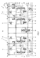
- FIG. 1 shows a circuit diagram of a hydraulic excavator control 1. This is constructed as a two-circuit system with two hydraulic circuits 2, 4, which are each supplied via a variable displacement pump, not shown, with pressure medium.
- the one with the in FIG. 1 shown control excavator has a chassis with two chains whose traction drives on the two circles 2, 4 are independently supplied with pressure medium.
- other consumers of the excavator such as a slewing gear, a stick, a spoon or a boom, are controlled via the two-circuit system.
- the excavator control according FIG. 1 realizing control block is designed in disc design, the two variable displacement pumps, not shown, are connected to pressure ports P 1 and P 2 of the control block.
- This also has a tank connection T and working connections A 1 , B 1 and A 2 , B 2 , to which the drive of the right or left chain is connected.
- the other consumers of the excavator such as the drive of the slewing gear, the hydraulic cylinder for actuating the stem, the spoon or the boom are connected.
- the illustrated control block also has two Load pressure connections, hereinafter referred to LS 1 and LS 2 , tapped via the load in the respective circuit 2, 4 acting load and the flow control valve (not shown) of the variable displacement, which is thus controlled in response to this highest load pressure.
- LS 1 and LS 2 Load pressure connections
- the control of the aforementioned consumer takes place in each case via a proportionally adjustable directional control valve 6, which in each case a pressure compensator 8 is connected downstream.
- the directional control valve 6 has a variable measuring orifice forming a speed part and a directional part, wherein the metering orifice of the pressure compensator 8 is connected upstream and the directional part downstream of the pressure compensator 8 is arranged.
- Each pressure compensator 8 is beauf beat in the closing direction of the load pressure and in the opening direction of the pressure downstream of the orifice of the directional control valve 6 beiller.
- the pressure balance piston adjusts depending on the applied control pressures in a control position in which the pressure drop across the metering orifice of the proportionally adjustable directional control valve 6 is kept contant, so that a load pressure independent Volumenstrom horrurtg is possible.
- Such LS controls are well known, so that can be dispensed with a detailed description of the structure of the directional control valve 6 and the downstream pressure compensator 8.
- the control of the directional control valve 6 takes place in each case via pilot valves 10, 12, via which a control pressure is applied to the frontal control surfaces of a slide of the directional control valve 6. These pilot valves are actuated, for example, as a function of the actuating movement of a joystick.
- each directional valve has two working ports, which are each connected via a working line 18 and 20 with the associated load ports A, B.
- an output connection of the directional control valve 6 is connected via a tank line 22 to the tank connection T of the control block.
- pressure limiting valves are provided in each case for limiting the maximum pressure supplied to the consumer, the pressure limiting valves with suction function delimiting the pressure at the working ports A 2 , B 2 , B 1 and B 3 and A 4 (not illustrated), so that in a lead of the consumer (negative load) pressure medium can be sucked out of the tank to avoid cavitation phenomena.
- a respective connected to the load pressure port LS of the two circuits 2, 4 load pressure signaling line 28, 30 is connected via an LS flow control valve 32 and 34 to the common tank line 22.
- the pressure compensators 8 are designed so that they report in their fully open end position at its input pressure (downstream pressure of the orifice plate) in the load pressure line 28 and 30, so that in this is always the highest load pressure in the respective circuit 2 or 4 ,
- the above-described directional valves with the associated pressure compensator 8, the pilot valves 10, 12 and the pressure relief valves 24, 25 may each be received in a disk or in a common control block.
- an interconnecting valve arrangement 38 is provided in an intermediate disc 36, via which the pressure lines 14, 16 of the two hydraulic circuits 2, 4 can be interconnected in certain operating states, so that the actuated consumers of both variable displacement pumps are connected together Pressure medium to be supplied.
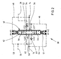
- this has a constructed as a pressure compensating interconnecting valve 40, the pressure compensator slide, hereinafter called valve body 42, with four control surfaces A1, A2, A3, A4 is executed, wherein two acting in one direction control surfaces A1, A2 with the pump pressure of the second circle and the load pressure of the first circle and acting in the other direction control surfaces A3, A4 are applied to the pump pressure of the first circle and the load pressure in the second circle , Accordingly, the control surface A1 via a pressure control line 44 to the pressure line 16 of the second circuit 4 and acting in the same direction control surface A2 via a LS control line 46 to the load pressure signaling line 28 of the first circle.
- control surfaces A3, A4 are connected via a further pressure control line 48 to the pressure line 14 and another LS control line 50 to the load pressure signaling line 30 of the second circle.
- the areas of the control surfaces A1, A2, A4 and A3 are the same.
- the valve body 42 is biased via a Zentrierfederan Aunt 51 in a middle blocking position, in the two connected to the pressure lines 14, 16 pressure ports P1 and P2 and two the first circuit 2 associated ports LS1 and LS1 'and two the second circuit 4 associated ports LS2, LS2 'are shut off.
- the LS input port LS1 is connected via an LS channel 52 and via a check valve 54, which opens in the direction of the port LS1, to the load pressure signaling line 28 of the first circuit 2, to which the LS output port LS1 'is also connected via an LS branch channel 56 ,
- the load pressure signaling line 30 of the second circuit 4 is connected via a further LS channel 58 and a further check valve 60 to the LS input connection LS2 and via a further LS channel 62 to the LS output connection LS2 '.
- the valve body 42 of the Verschschaltventils 40 upwards (see FIG. 2 ) are moved to one of the control positions marked b or down to one of the control positions marked with a.
- control positions a, b the summed from the circle with the higher pressure level to the other circle Pressure fluid flow rate throttled via the Zuschaltventil 40 to the lower pressure level.
- the control position is established when the pressure difference between the pump pressure and the load pressure in the first circuit is approximately equal to that in the second circuit.
- a pressure medium from the second circle 4 is summed to the pressure medium flow rate of the first circle 2, wherein the LS-LS1 and LS2 'are connected to each other, while the two other LS-LS2, LS1' are locked against each other.
- the check valve 54 prevents that at a lower load pressure in the first circuit 2, the higher load pressure of the second circuit 4 is reported in the first circle, so that in accordance with the first circle associated variable displacement pump is not raised in this case. In the case in which the higher load pressure in the first circuit 2 is applied, it is reported via the opening check valve 54 and the two connected LS connections LS1 and LS2 'to the variable displacement pump of the second circuit and this raised accordingly.
- the pressure ports P1 and P2 are connected to one another so that pressure medium from the first circuit is summed to the pressure medium volume flow of the second circuit and the LS ports LS2 and LS1 'are connected to one another, wherein the non-return valve 60 prevents a lower load pressure in the first circuit 2 (in the load pressure signaling line 28) is reported to the load pressure signaling line 30 of the second circuit 4.
- FIG. 3 is a concrete embodiment of a Verschschaltventilan extract 38 according to FIG. 2 shown.
- FIG. 3 shows a longitudinal section through the valve disc 36 or by a the Verschschaltventilan Aunt 38 receiving valve housing.
- a valve bore 64 is formed, in the pressure compensator valve or valve body 42 is guided axially displaceable.
- the valve bore 64 is extended in its central region to two pressure chambers 66, 68, which are separated from one another by a housing web 70.
- the pressure chamber 66 is connected to the pressure port P1 and the pressure chamber 68 to the pressure port P2.
- the valve bore is widened in the radial direction in each case to form LS annular spaces 70, 72 and 74, 76, wherein the outer annular spaces 70, 76 are connected to the load pressure signaling channel 30 and thus in these spaces the h O Last load pressure of the second circle 4 is applied.
- the two inner annular spaces 72, 74 are acted upon in accordance with the load pressure signaling line 28 and thus with the highest load pressure of the first circuit 2.
- the connection of the two other annular spaces 70, 76 to the load pressure signaling line 30 via corresponding channels with integrated check valve 60 (in Fig. 3 not shown).
- the valve body 42 has a central control collar 78 on which two control edges 80, 82 designed with fine control notches are formed. Upon axial displacement of the valve body 42 via one of the control edges 80, 82, the connection between the two pressure chambers 66, 68 opened, which - as mentioned above - are connected to the pressure lines 14 and 16 respectively.
- the pressure chamber 66 is connected to the port P1 and the pressure chamber 68 to the port P2 - for ease of understanding, the terminal designations in the illustration according to FIG. 3 added in parentheses.
- the valve body 42 has on both sides two collars 84, 86 which are each connected via a radially recessed piston neck to an external control collar 88 or 90.
- Each control collar 88, 90 is in one Reduction sleeve 92 and 94 out, respectively, which are inserted into an end-side, step-shaped enlarged end portion of the valve bore 64 and thus reduce the effective guide diameter for the valve body 42 and create a surface difference.
- the control surface A3 limited with the adjacent end face of the Reduzierbuchse 92 a space 96 in which the pressure of the pressure line 14 and thus at the pressure port P1 is applied.
- the two outer control collars 88, 90 are each slightly downgraded by a piston neck 100, 102 in the middle, so that in each case a control edge 104, 106 is formed.
- the two end surfaces of the valve body 42 form the control surfaces A1 and A4 (see FIG. 2 ), which are acted upon by the pressure in the pressure line 16 of the second circle or with the highest load pressure of the second circle.
- end surfaces A1, A4 and the annular end faces A2, A3 are each designed with the same area.
- the valve body 42 is biased by the Zentrierfederan effet 51 in its illustrated mid-position.
- This Zentrierfederan effet 51 also acts as a control spring arrangement, and is the concrete Embodiment with two control springs 108, 110 executed, the spring constant is designed so that it is slightly below the pump Ap.
- the spring force of a control spring 108, 110 corresponds approximately to a pressure of delta-p difference: 3 to 6 bar (determined from experiment).
- the two control springs 108, 110 are each supported on a spring bushing 112, 114 screwed into the valve bore 64 and each engage via a spring plate 116, 118 on the end faces A1, A4 of the valve body 42.
- the control spring 108, 110 assigning, radially enlarged Ringstim lake the Reduzierbuchsen 92, 94 serve as an end stop for the spring plates 116, 118. Through these two end stops and the illustrated center position of the valve body 42 is determined.
- the operating according to the Druckwaagenpririzip interconnecting valve 40 thereby adjusts itself to a control position, so that the funded by the variable displacement pump of the second circuit 4 pressure medium is throttled to the pressure level in the first circuit 2 and the pressure differences (pump pressure-load pressure) in both circuits are approximately equal ,
- the solution according to the invention is characterized by an extremely compact design, which can be realized with little device complexity.
- the interposing valve arrangement has a connection valve with two pressure connections, two LS input and two LS output connections, wherein a valve body of the interposing valve is designed with four control surfaces, two of which act in one direction control surfaces from the highest load pressure in the first circuit and the pump pressure in second circuit and acting in the other direction control surfaces of the highest load pressure in the second circuit and the pump pressure in the first circuit are acted upon.
Landscapes
- Engineering & Computer Science (AREA)
- General Engineering & Computer Science (AREA)
- Physics & Mathematics (AREA)
- Fluid Mechanics (AREA)
- Mechanical Engineering (AREA)
- Mining & Mineral Resources (AREA)
- Civil Engineering (AREA)
- Structural Engineering (AREA)
- Fluid-Pressure Circuits (AREA)
- Operation Control Of Excavators (AREA)
Description
- Die Erfindung betrifft eine Zusammenschaltventilanordnung für ein hydraulisches Zweikreissystem zur Ansteuerung von Verbrauchern eines mobilen Gerätes, insbesondere eines Raupengerätes gemäss dem Patentanspruch 1, und ein Zweikreissystem mit einer derartigen zusammenschaltventilanordnung.
- In der
US 6,170,261 B1 ist ein hydraulisches Zweikreissystem eines mobilen Gerätes, beispielsweise eines Ketten- oder Raupengeräts offenbart. Bei derartigen Raupengeräten hat das Fahrwerk zwei Ketten, die jeweils über einen der hydraulischen Kreise getrennt voneinander ansteuerbar sind. An die beiden hydraulischen Kreise des Kettengerätes sind des Weiteren noch ein Drehwerk sowie Aggregate der Ausrüstung, wie beispielsweise der Ausleger, der Löffelstiel und der Löffel angeschlossen. Jeder der beiden hydraulischen Kreise wird von einer Verstellpumpe mit Druckmittel gespeist, die in Abhängigkeit vom jeweils höchsten Lastdruck der Verbraucher im jeweils zugeordneten Kreis angesteuert werden. - Für den Fall, dass neben den beiden Ketten noch zumindest ein Verbraucher der Ausrüstung betätigt werden soll, besteht die Möglichkeit, zur Vermeidung einer Druckmittelunterversorgung beide hydraulischen Kreise zusammenzuschalten. Bei der in der
US 6,170,261 B1 offenbarten Lösung erfolgt diese Zusammenschaltung der beiden hydraulischen Kreise über ein Zusammenschaltventil, über das die mit den beiden Pumpen verbundenen Druckleitungen sowie die Lastdruckmeldeleitungen der beiden Kreise zusammengeschaltet werden. Die Ansteuerung des Zusammen schaltventils erfolgt in Abhängigkeit von der Druckmittelzufuhr zum zusätzlichen Verbraucher. Zusätzlich kann der Bediener manuell eingreifen und die beiden Kreise zusammenschalten. - Nachteilig bei dieser Lösung ist, dass beispielsweise bei der Ansteuerung eines an den einen hydraulischen Kreis angeschlossenen Verbrauchers mit hohem Druckmittelbedarf und geringem Druck und bei Ansteuerung eines an den anderen Kreis angeschlossenen Verbrauchers mit geringem Mengenbedarf und hohem Druck beide Kreise über das Zusammenschaltventil verbunden werden, so dass der höhere Lastdruck des letztgenannten Kreises auch im erstgenannten Kreis anliegt. Aufgrund dieses höheren Lastdruckes wird die Pumpe des ersten Kreises hochgefahren, so dass beide Kreise auf das höhere Druckniveau angehoben werden. Der Druck im erstgenannt hydraulischen Kreis muss dann entsprechend wieder auf das erforderliche Druckniveau heruntergeregelt werden, was erhebliche Energieverluste zur Folge hat. Ein weiterer Nachteil besteht darin, dass bei der Lösung gemäss der
US 6,170,261 B1 ein erheblicher schaltungstechnischer Aufwand zum Abgreifen des Lastdrucks vom zusätzlichen Verbraucher und zur Ansteuerung des Zusammenschaltventils erforderlich ist. - In der
DE 102 55 738 A1 der Anmelderin ist ein verbessertes Zweikreissystem gezeigt, bei dem eine Zusammenschaltventilanordnung mit zwei Druckwaagen ausgeführt ist, von denen jeweils eine einem der Kreise zugeordnet ist und über die in Abhängigkeit vom Lastdruck und vom Pumpendruck im zugeordneten Kreis die Verbindung zum anderen Kreis aufsteuerbar ist. Nachteilig bei dieser Lösung ist, dass die Zusammenschaltventilanordnung einen vergleichsweise komplexen Aufbau hat. - Demgegenüber liegt der Erfindung die Aufgabe zugrunde, ein hydraulisches Zweikreissystem und eine dafür geeignete Zusammenschaltventilanordnung mit einfachem Aufbau zu schaffen.
- Diese Aufgabe wird hinsichtlich des hydraulischen Zweikreissystems mit den Merkmalen des Patentanspruchs 2 und hinsichtlich der Zusammenschaltventilanordnung durch die Merkmale des unabhängigen Patentanspruchs 1 gelöst.
- Erfindungsgemäß ist die zum Summieren der Druckmittelvolumenströme eines Zweikreissystems erforderliche Zusammenschaltventilanordnung im Wesentlichen durch ein Zusammenschaltventil ausgebildet, das mit zumindest vier Steuerflächen ausgeführt ist, wobei zwei in einer Richtung wirkende Steuerflächen vom höchsten Lastdruck in einem ersten Kreis und vom Pumpendruck im zweiten Kreis und die in der anderen Richtung wirkenden Steuerflächen vom höchsten Lastdruck in diesem Kreis und vom Pumpendruck im erstgenannten Kreis beaufschlagt sind. In Abhängigkeit von der resultierenden Steuerdruckdifferenz können dann zum Summieren zwei Druckanschlüsse und ein dem ersten Kreis zugeordneter LS-Eingangsanschluß mit einem dem zweiten Kreis zugeordneten LS-Ausgangsanschluß verbunden werden, wodurch verhindert wird, dass ein im einen der Kreise wirkender höherer Lastdruck bei geringem Druckmittelbedarf in den anderen Kreis mit niedrigerem Lastdruck und hohem Druckmittelbedarf gemeldet wird. Es wird in beiden Kreisen lediglich der den tatsächlichen Anforderungen entsprechende Lastdruck zur jeweils zugeordneten Verstellpumpe gemeldet, so dass in dem Fall, in dem in einem der Kreise ein hoher Druck bei geringem Druckmittelbedarf anliegt, die Verstellpumpe dieses Kreises nicht hochgefahren wird und somit die Energieverluste gegenüber herkömmlichen Lösungen erheblich minimiert sind. Diese Lösung lässt es jedoch zu, dass in dem Fall, in dem in einem der Kreise ein hoher Druck bei hohem Druckmittelbedarf anliegt, dieser hohe Druck in den zweiten Kreis gemeldet wird, falls in diesem ein niedrigerer Lastdruck anliegt.
- Bei einem bevorzugten Ausführungsbeispiel ist ein Ventilkörper des Zusammenschaltventils über eine Zentrierfederanordnung in eine Sperrstellung vorgespannt.
- Um zu verhindern, dass bei geöffnetem Zusammenschaltventil ein höherer Lastdruck von dem zugeschalteten Kreis in den anderen Kreis gemeldet wird, sind in den Lastdruckleitungen Rückschlagventile vorgesehen.
- Gemäß einem Ausführungsbeispiel ist eine LS-Leitung eines Kreises jeweils mit einem dem anderen Kreis zugeordneten LS-Ausgangsanschluß des Zusammenschaltventils verbunden.
- Bei einem besonders bevorzugten Ausführungsbeispiel sind die vom Pumpendruck und dem Lastdruck beaufschlagten Steuerflächen des Ventilkörpers gleich groß ausgeführt.
- Das Zusammenschaltventil ist besonders einfach aufgebaut, wenn der Pumpendruck und der Lastdruck eines Kreises jeweils auf eine einen Federraum begrenzende rückseitige Stirnfläche und der Pumpendruck und der Lastdruck des anderen Kreises auf Ringstimflächen des Ventilkörpers wirken.
- Ein Ventilkörper des Zusammenschaltventils wird vorzugsweise mit einem mittigen Steuerbund ausgeführt, an dem zwei Steuerkanten zum Aufsteuem der Verbindung zwischen den beiden Druckanschlüssen ausgebildet sind. Der Ventilkörper hat desweiteren zwei aussenliegende LS-Steuerbunde, an denen jeweils eine Steuerkante zum Aufsteuern der Verbindung zwischen dem LS-Eingangsanschluß des einen Kreises und dem LS-Ausgangsanschluß des anderen Kreises ausgebildet ist. Die federraumseitigen Rückflächen der beiden Steuerbunde bilden dabei die oben genannten rückseitigen Stirnflächen aus.
- Vorzugsweise ist jeweils zwischen dem mittigen Steuerbund und einem LS-Steuerbund ein weiterer Bund ausgebildet, an den die genannte Ringstimfläche angeordnet ist.
- Ein derartiger Aufbau ermöglicht es, den Ventilkörper symmetrisch auszubilden, so dass die Herstellung und Montage besonders einfach ist.
- Der Aufbau des Zusammenschaltventils ist weiter vereinfacht, wenn die vorstehend beschriebenen Rückschlagventile in das Ventilgehäuse des Zusammenschaltventils integriert sind.
- Sonstige vorteilhafte Weiterbildungen der Erfindung sind Gegenstand weiterer Unteransprüche.
- Ein bevorzugtes Ausführungsbeispiel der Erfindung wird im Folgenden anhand schematischer Zeichnungen näher erläutert:
-
Figur 1 ein Schaltschema eines Steuerblocks zur Ansteuerung eines Raupengerätes; -
Figur 2 ein Schaltsymbol einer Zusammenschaltventilanordnung eines Zwei- oder Mehrkreissystems gemäßFigur 1 und -
Figur 3 eine konkrete Ausführung der Zusammenschaltventilanordnung ausFigur 1 . -
Figur 1 zeigt ein Schaltschema einer hydraulischen Baggersteuerung 1. Diese ist als Zweikreissystem mit zwei hydraulischen Kreisen 2, 4 aufgebaut, die jeweils über eine nicht dargestellte Verstellpumpe mit Druckmittel versorgt werden. Der mit der inFigur 1 dargestellten Steuerung versehene Bagger hat ein Fahrwerk mit zwei Ketten, deren Fahrantriebe über die beiden Kreise 2, 4 unabhängig voneinander mit Druckmittel versorgbar sind. Neben dem Fahrantrieb werden über das Zweikreissystem noch weitere Verbraucher des Baggers, wie beispielsweise ein Drehwerk, ein Stiel, ein Löffel oder ein Ausleger angesteuert. - Der die Baggersteuerung gemäss
Figur 1 realisierende Steuerblock ist in Scheibenbauweise ausgeführt, wobei die beiden nicht dargestellten Verstellpumpen an Druckanschlüsse P1 und P2 des Steuerblocks angeschlossen sind. Dieser hat des Weiteren noch einen Tankanschluss T sowie Arbeitsanschlüsse A1, B1 sowie A2, B2, an die der Antrieb der rechten bzw. linken Kette angeschlossen ist. An weitere Anschlüsse A3, B3 und A4, B4 etc. werden die weiteren Verbraucher des Baggers, wie beispielsweise der Antrieb des Drehwerks, die Hydrozylinder zur Betätigung des Stiels, des Löffels oder des Auslegers angeschlossen. Beim dargestellten Ausführungsbeispiel sei angenommen, dass an die Anschlüsse A2, B2 der Ausleger und an den Anschluss A4, B4 der Löffel angeschlossen sind. - Der dargestellte Steuerblock hat des Weiteren zwei Lastdruckanschlüsse, im folgenden LS1 und LS2 genannt, über die der im jeweiligen Kreis 2, 4 wirkende Lastdruck abgegriffen und zum Förderstromregelventil (nicht dargestellt) der Verstellpumpe geführt wird, die somit in Abhängigkeit von diesem höchsten Lastdruck angesteuert wird.
- Die Ansteuerung der vorgenannten Verbraucher erfolgt jeweils über ein proportional verstellbares Wegeventil 6, dem jeweils eine Druckwaage 8 nachgeschaltet ist. Das Wegeventil 6 hat einen eine veränderliche Messblende ausbildenden Geschwindigkeitsteil und einen Richtungsteil, wobei die Messblende der Druckwaage 8 vorgeschaltet ist und der Richtungsteil stromabwärts der Druckwaage 8 angeordnet ist. Jede Druckwaage 8 ist in Schliessrichtung vom Lastdruck und in Öffnungsrichtung von dem Druck stromabwärts der Messblende des Wegeventils 6 beauf schlagt. Der Druckwaagenkolben stellt sich in Abhängigkeit von den anliegenden Steuerdrücken in eine Regelposition ein, in der der Druckabfall über der Messblende des proportional verstellbaren Wegeventils 6 kontant gehalten wird, so dass eine lastdruckunabhängige Volumenstromsteuerurtg ermöglicht wird. Derartige LS-Steuerungen sind hinlänglich bekannt, so dass auf eine ausführliche Beschreibung des Aufbaus des Wegeventils 6 und der nachgeschalteten Druckwaage 8 verzichtet werden kann. Die Ansteuerung des Wegeventils 6 erfolgt jeweils über Pilotventile 10, 12, über die ein Steuerdruck an die stirnseitigen Steuerflächen eines Schiebers des Wegeventils 6 angelegt wird. Diese Pilotventile werden beispielsweise in Abhängigkeit von der Stellbewegung eines Joysticks betätigt.
- Die Anschlüsse der Wegeventile 6 sind über eine Druckleitung 14, 16 mit dem Druckanschluss P1 bzw. P2 verbunden. Des Weiteren hat jedes Wegeventil zwei Arbeitsanschlüsse, die jeweils über eine Arbeitsleitung 18 bzw. 20 mit den zugeordneten Verbraucheranschlüssen A, B verbunden sind. Zur Rückführung des Druckmittels vom Verbraucher ist ein Ausgangsanschluss des Wegeventils 6 über eine Tankleitung 22 mit dem Tankanschluss T des Steuerblocks verbunden.
- In den Arbeitsleitungen sind zur Begrenzung des maximalen, zum Verbraucher geführten Druckes jeweils noch Druckbegrenzungsventile vorgesehen, wobei die den Druck an den Arbeitsanschlüssen A2, B2, B1 und B3 sowie A4 (nicht dargestellt) begrenzenden Druckbegrenzungsventile mit Nachsaugfunktion ausgeführt sind, so dass bei einem Voreilen des Verbrauchers (negative Last) Druckmittel aus dem Tank nachgesaugt werden kann um Kavitätserscheinungen zu vermeiden. Eine jeweils an den Lastdruckanschluss LS der beiden Kreise 2, 4 angeschlossene Lastdruckmeldeleitung 28, 30 ist über ein LS-Stromregelventil 32 bzw. 34 mit der gemeinsamen Tankleitung 22 verbunden.
- Die Druckwaagen 8 sind so ausgeführt, dass sie in ihrer voll aufgesteuerten Endposition den an ihrem Eingang anliegenden Druck (Druck stromabwärts der Messblende) in die Lastdruckleitung 28 bzw. 30 melden, so dass in dieser stets der höchste Lastdruck im jeweiligen Kreis 2 oder 4 liegt.
- Die vorbeschriebenen Wegeventile mit der zugeordneten Druckwaage 8, den Pilotventilen 10, 12 sowie den Druckbegrenzungsventilen 24, 25 können jeweils in einer Scheibe oder in einem gemeinsamen Steuerblock aufgenommen sein. Zur Verbindung der beiden hydraulischen Kreise 2, 4 ist in einer Zwischenscheibe 36 eine Zusammenschaltventilanordnung 38 vorgesehen, über die bei bestimmten Betriebszuständen die Druckleitungen 14, 16 der beiden hydraulischen Kreise 2, 4 zusammengeschaltet werden können, so dass die angesteuerten Verbraucher von beiden Verstellpumpen gemeinsam mit Druckmittel versorgt werden.
- Der Aufbau der Zusammenschaltventilanordnung wird im Folgenden anhand der
Figuren 2 und3 erläutert. - Gemäß dem in
Figur 2 dargestellten Schaltsymbol der Zusammenschaltventilanordnung 38, hat diese ein als Druckwaage aufgebautes Zusammenschaltventil 40, dessen Druckwaagenschieber, im Folgenden Ventilkörper 42 genannt, mit vier Steuerflächen A1, A2, A3, A4 ausgeführt ist, wobei zwei in einer Richtung wirkende Steuerflächen A1, A2 mit dem Pumpendruck des zweiten Kreises und dem Lastdruck des ersten Kreises und die in der anderen Richtung wirkenden Steuerflächen A3, A4 mit dem Pumpendruck des ersten Kreises und dem Lastdruck im zweiten Kreis beaufschlagt sind. Entsprechend ist die Steuerfläche A1 über eine Drucksteuerleitung 44 mit der Druckleitung 16 des zweiten Kreises 4 und die in gleicher Richtung wirkenden Steuerfläche A2 über eine LS-Steuerleitung 46 mit der Lastdruckmeldeleitung 28 des ersten Kreises verbunden. Die in der Gegenrichtung wirksamen Steuerflächen A3, A4 sind über eine weitere Drucksteuerleitung 48 mit der Druckleitung 14 bzw. eine weitere LS-Steuerleitung 50 mit der Lastdruckmeldeleitung 30 des zweiten Kreises verbunden. Die Flächen der Steuerflächen A1, A2, A4 und A3 sind jeweils gleich. - Der Ventilkörper 42 ist über eine Zentrierfederanordnung 51 in eine mittlere Sperrstellung vorgespannt, in der zwei mit dem Druckleitungen 14, 16 verbundene Druckanschlüsse P1 und P2 sowie zwei dem ersten Kreis 2 zugeordneten Anschlüsse LS1 und LS1' und zwei dem zweiten Kreis 4 zugeordnete Anschlüsse LS2, LS2' abgesperrt sind.
- Der LS-Eingangsanschluss LS1 ist über einen LS-Kanal 52 und über ein in Richtung zum Anschluss LS1 öffnendes Rückschlagventil 54 mit der Lastdruckmeldeleitung 28 des ersten Kreises 2 verbunden, an die auch der LS-Ausgangsanschluss LS1' über einen LS-Zweigkanal 56 angeschlossen ist. Entsprechend ist die Lastdruckmeldeleitung 30 des zweiten Kreises 4 über einen weiteren LS-Kanal 58 und ein weiteres Rückschlagventil 60 mit dem LS-Eingangsanschluss LS2 und über einen weiteren LS-Kanal 62 mit dem LS-Ausgangsanschluss LS2' verbunden. Je nach anliegender Steuerdruckdifferenz kann der Ventilkörper 42 des Zusammenschaltventils 40 nach oben (Ansicht nach
Figur 2 ) in eine der mit b gekennzeichneten Regelpositionen oder nach unten nach eine der mit a gekennzeichneten Regelpositionen verschoben werden. In den Regelpositionen a, b wird der vom Kreis mit dem höheren Druckniveau zum anderen Kreis summierte Druckmittelvolumenstrom über das Zuschaltventil 40 auf das niedrigere Druckniveau abgedrosselt. Die Regelposition stellt sich ein, wenn die Druckdifferenz zwischen Pumpendruck und Lastdruck im ersten Kreis etwa gleich derjenigen im zweiten Kreis ist. In den Regelpositionen a wird Druckmittel vom zweiten Kreis 4 zum Druckmittelvolumenstrom des ersten Kreises 2 summiert, wobei auch die LS-Anschlüsse LS1 und LS2' miteinander verbunden sind, während die beiden anderen LS-Anschlüsse LS2, LS1' gegeneinander gesperrt sind. Das Rückschlagventil 54 verhindert dabei, dass bei einem niedrigeren Lastdruck im ersten Kreis 2 der höhere Lastdruck des zweiten Kreises 4 in den ersten Kreis gemeldet wird, so dass entsprechend die dem ersten Kreis zugeordnete Verstellpumpe in diesem Fall nicht hochgefahren wird. In dem Fall, in dem der höhere Lastdruck im ersten Kreis 2 anliegt, wird diese über das sich öffnende Rückschlagventil 54 und die beiden verbundenen LS-Anschlüsse LS1 und LS2' zur Verstellpumpe des zweiten Kreises gemeldet und diese entsprechend hochgefahren. - Entsprechend werden bei einer Verschiebung in einer der Regelpositionen b die Druckanschlüsse P1 und P2 miteinander verbunden, so dass Druckmittel vom ersten Kreis zum Druckmittelvolumenstrom des zweiten Kreises summiert wird und die LS-Anschlüsse LS2 und LS1' miteinander verbunden sind, wobei das Rückschlagventil 60 verhindert, dass ein niedrigerer Lastdruck im ersten Kreis 2 (in der Lastdruckmeldeleitung 28) in die Lastdruckmeldeleitung 30 des zweiten Kreises 4 gemeldet wird.
- In
Figur 3 ist ein konkretes Ausführungsbeispiel einer Zusammenschaltventilanordnung 38 gemäßFigur 2 dargestellt. - Wie eingangs ausgeführt, kann diese in die Zwischenscheibe 36 des Steuerblocks integriert sein oder aber als eigenes Ventil auf den Steuerblock aufgesetzt werden.
Figur 3 zeigt einen Längsschnitt durch die Ventilscheibe 36 oder durch ein die Zusammenschaltventilanordnung 38 aufnehmendes Ventilgehäuse. In der Ventilscheibe 36 ist eine Ventilbohrung 64 ausgebildet, in der der Druckwaagenschieber oder Ventilkörper 42 axialverschiebbar geführt ist. Die Ventilbohrung 64 ist in ihrem mittleren Bereich zu zwei Druckkammern 66, 68 erweitert, die von einem Gehäusesteg 70 von einander getrennt sind. Die Druckkammer 66 ist dabei mit dem Druckanschluss P1 und die Druckkammer 68 mit dem Druckanschluss P2 verbunden. Zu ihren Endabschnitten hin ist die Ventilbohrung in Radialrichtung jeweils zu LS-Ringräumen 70, 72 und 74, 76 erweitert, wobei die aussenliegenden Ringräume 70, 76 mit dem Lastdruckmeldekanal 30 verbunden sind und somit in diesen Räumen der ho chste Lastdruck des zweiten Kreises 4 anliegt. Die beiden innenliegenden Ringräume 72, 74 sind entsprechend mit der Lastdruckmeldeleitung 28 und somit mit dem höchsten Lastdruck des ersten Kreises 2 beaufschlagt. In der Schnittdarstellung gemäßFigur 3 sind die Lastdruckmeldeleitungen 28, der zum Ringraum 72 führende LS-Kanal 52 und das darin angeordnete Rückschlagventil 54 sowie der zum Ringraum 74 führende LS-Zweigkanal 56 dargestellt. Die Anbindung der beiden anderen Ringräume 70, 76 an die Lastdruckmeldeleitung 30 erfolgt über entsprechende Kanäle mit integriertem Rückschlagventil 60 (inFig. 3 nicht dargestellt). - Der Ventilkörper 42 hat einen mittleren Steuerbund 78 an dem zwei mit Feinsteuerkerben ausgeführte Steuerkanten 80, 82 ausgebildet sind. Bei Axialverschiebung des Ventilkörpers 42 wird über eine der Steuerkanten 80, 82 die Verbindung zwischen den beiden Druckkammern 66, 68 aufgesteuert, die - wie vorstehend erwähnt - an die Druckleitungen 14 bzw. 16 angeschlossen sind. In der Darstellung gemäß
Figur 2 ist die Druckkammer 66 mit dem Anschluss P1 und die Druckkammer 68 mit dem Anschluss P2 verbunden - zum einfacheren Verständnis sind die Anschlussbezeichnungen in der Darstellung gemäßFigur 3 in Klammern hinzugefügt. - Im Axialabstand zum mittleren Steuerbund 78 hat der Ventilkörper 42 beidseitig zwei Bunde 84, 86, die jeweils über einen radial zurückgesetzten Kolbenhals mit einem aussenliegenden Steuerbund 88 bzw. 90 verbunden sind. Jeder Steuerbund 88, 90 ist in einer Reduzierhülse 92 bzw. 94 geführt, die jeweils in einen stirnseitigen, stufenförmig erweiterten Endabschnitt der Ventilbohrung 64 eingesetzt sind und somit den wirksamen Führungsdurchmesser für den Ventilkörper 42 verringern und eine Flächendifferenz schaffen. An den zu den Steuerbunden 88, 90 weisenden Stimflächen der Bunde 84 und 86 ist jeweils eine Ringstirnfläche vorgesehen, die die Steuerflächen A2 bzw. A3 bilden.
- Die Steuerfläche A3 begrenzt mit der benachbarten Stirnfläche der Reduzierbuchse 92 einen Raum 96, in dem der Druck der Druckleitung 14 und somit am Druckanschluss P1 anliegt. Die Ringstimfläche A2 des Bundes 86 begrenzt mit der benachbarten Stirnfläche der Reduzierbuchse 94 einen weiteren Raum 98, in dem entsprechend der Druck in der Druckleitung 16 und somit der Druck am Druckanschluss P2 anliegt. Die beiden aussenliegenden Steuerbunde 88, 90 sind jeweils durch einen Kolbenhals 100, 102 mittig etwas zurückgestuft, so dass jeweils eine Steuerkante 104, 106 gebildet ist. Durch die in
Figur 3 links liegende Steuerkante 104 kann die Verbindung zwischen den Ringräumen 72 und 70 und durch die rechte Steuerkante 106 die Verbindung zwischen den Ringräumen 74, 76 aufgesteuert werden. In der dargestellten Grundposition des Ventilkörpers 42 ist die Verbindung durch die Steuerkanten 104 und 106 abgesperrt. - Die beiden Stirnflächen des Ventilkörpers 42 bilden die Steuerflächen A1 und A4 (siehe
Figur 2 ) aus, die mit dem Druck in der Druckleitung 16 des zweiten Kreises bzw. mit dem höchsten Lastdruck des zweiten Kreises beaufschlagt sind. - In dem dargestellten Ausführungsbeispiel sind die Stirnflächen A1, A4 sowie die Ringstirnflächen A2, A3 jeweils mit gleicher Fläche ausgeführt.
- Wie bereits anhand
Figur 2 erläutert, wird der Ventilkörper 42 durch die Zentrierfederanordnung 51 in seine dargestellte Mittstellung vorgespannt. Diese Zentrierfederanordnung 51 wirkt auch als Regelfederanordnung, und ist beim konkreten Ausführungsbeispiel mit zwei Regelfedern 108, 110 ausgeführt, deren Federkonstante so ausgelegt ist, dass sie etwas unterhalb des Pumpen-Δp liegt. Bei einem Pumpen-Δp von etwa 20 bar, entspricht die Federkraft einer Regelfeder 108, 110 etwa einem Druck von delta-p-Unterschied: 3 bis 6 bar (aus Versuch ermittelt). - Die beiden Regelfedem 108, 110 sind jeweils an einer in die Ventilbohrung 64 eingeschraubten Federbuchse 112, 114 abgestützt und greifen jeweils über einen Federteller 116, 118 an den Stirnflächen A1, A4 des Ventilkörpers 42 an. Die den Regelfedem 108, 110 zuweisenden, radial vergrößerten Ringstimflächen der Reduzierbuchsen 92, 94 dienen dabei als Endanschlag für die Federteller 116, 118. Durch diese beiden Endanschläge ist auch die dargestellte Mittelposition des Ventilkörpers 42 bestimmt.
- Zum besseren Verständnis der Funktion wird im Folgenden ein Betriebszustand der Baggersteuerung erläutert.
- Es sei angenommen, dass der an die Arbeitsanschlüsse A2, B2 angeschlossene Verbraucher, beispielsweise der Stiel, viel Druckmittel benötigt und entsprechend vergleichsweise geringer Pumpendruck im hydraulischen Kreis 2 anliegt. Der an die Arbeitsanschlüsse A4, B4 des zweiten Kreises angeschlossene Verbraucher, beispielsweise der Ausleger, soll dagegen nur eine geringe Druckmittelmenge bei einem vergleichsweise hohen Pumpendruck benötigen. Aufgrund des Druckabfalls im ersten Kreis 2 (niedriger Druck in der Druckleitung 14) wird der Ventilkörper 86 gegen die Kraft der Regelfeder 108 in der Darstellung gemäß
Figur 3 nach links verschoben, so dass über die Steuerkante 80 mit ihren Feinsteuerkerben der Druckmittelströmungspfad zwischen den Druckkammern 86, 66 aufgesteuert wird und entsprechend Druckmittel vom zweiten Kreis 4 zum ersten Kreis 1 summiert wird (Druckmittelströmung von P1 nach P2 des Zusammenschaltventils 40). Parallel dazu wird über die Steuerkante 104 die Verbindung zwischen den beiden LS-Ringräumen 70, 72 aufgesteuert, so dass die Verbindung zwischen dem LS-Eingangsanschluss LS1 und dem LS-Ausgangsanschluss LS2' geöffnet ist. Durch das Rückschlagventil 54 wird verhindert, dass ein höherer Lastdruck im zweiten Kreis 4 in den ersten Kreis 2 gemeldet wird, der Druckmittel von dem zweiten Kreis aufnimmt. Das nach dem Druckwaagenpririzip arbeitende Zusammenschaltventil 40 stellt sich dabei in eine Regelposition ein, so dass das von der Verstellpumpe des zweiten Kreises 4 geförderte Druckmittel auf das Druckniveau im ersten Kreis 2 abgedrosselt wird und die Druckdifferenzen (Pumpendruck-Lastdruck) in beiden Kreisen etwa gleich sind. - Die Energieeinsparung für diesen Fall berechnet sich wie folgt:
PStiel = 60 bar QStiel= 300l/min PAusleger = 140 bar QAusleger= 100l/min 2-Kreis: QPumpe1 = QPumpe2 = 200l/min 1-Kreis: QP(1-Kreis) = 400l/min 

=> Leistungseinsparung für dieses Bsp.: 28.6%
- Bei einer Summierung vom ersten Kreis 2 in den zweiten Kreis 4 wird entsprechend der Ventilkörper 42 in der Darstellung gemäß
Figur 3 nach rechts verschoben, so dass über die Steuerkante 82 die Verbindung vom Druckraum 66 zum Druckraum 68 und somit der Druckmittelströmungspfad vom Druckanschluss P1 zum Druckanschluss P2 aufgesteuert wird. Gleichzeitig wird über die Steuerkante 106 die Verbindung zwischen den beiden LS-Ringräumen 74, 76 aufgesteuert, wobei ein höherer Lastdruck in dem Druckmittel empfangenden Kreis 4 an die Verstellpumpe des ersten Kreises 2 gemeldet wird, diese entsprechend hochgefahren wird. Sollte der Lastdruck im zweiten Kreis 4 niedriger sein, so verhindert das Rückschlagventil 60, dass der höhere Lastdruck in den Kreis gemeldet wird. - Die erfindungsgemäße Lösung zeichnet sich durch einen äußerst kompakten Aufbau aus, der sich mit geringem vorrichtungstechnischen Aufwand realisieren lässt.
- Offenbart sind ein hydraulisches Zweikreissystem zur Ansteuerung von Verbrauchern eines mobilen Gerätes beispielsweise eines Raupengerätes und einefür ein derartiges Zweikreissystem geeignete Zusammenschaltventilanordnung, über die die beiden Kreise zum Summieren zusammengeschaltet werden können. Erfindungsgemäß hat die Zusammenschaltventilanordnung ein Zusammenschaltventil mit zwei Druckanschlüssen, zwei LS-Eingangs- und zwei LS-Ausgangsanschlüssen, wobei ein Ventilkörper des Zusammenschaltventils mit vier Steuerflächen ausgeführt ist, von denen zwei in einer Richtung wirkende Steuerflächen vom höchsten Lastdruck im ersten Kreis und vom Pumpendruck im zweiten Kreis und die der anderen Richtung wirkenden Steuerflächen vom höchsten Lastdruck im zweiten Kreis und vom Pumpendruck im ersten Kreis beaufschlagt sind.
Claims (12)
- Zusammenschaltventilanordnung (38) für ein hydraulisches Zweikreissystem, mit einem einzigen Zusammenschaltventil (40), das zwei Druckanschlüsse (P1, P2), zwei LS-Eingangs- und zwei LS-Ausgangsanschlüsse (LS1, LS2; LS1', LS2') sowie einen einzigen Ventilkörper (42) hat, der in einer Richtung vom höchsten Lastdruck im ersten Kreis (2) und vom Pumpendruck im zweiten Kreis (4) und in der anderen Richtung vom höchsten Lastdruck im zweiten Kreis (4) und vom Pumpendruck im ersten Kreis (2) beaufschlagbar ist, so dass in Abhängigkeit von der resultierenden, auf den Ventilkörper (42) wirkenden Steuerdruckdifferenz die beiden Druckanschlüsse (P1, P2) und ein einem Kreis zugeordneter LS-Eingangsanschluss (LS1, LS2) mit einem dem anderen Kreis zugeordneten LS-Ausgangsanschluss (LS1', LS2') verbindbar sind.
- Hydraulisches Zweikreissystem zur Ansteuerung von Verbrauchern eines mobilen Gerätes, insbesondere eines Raupengerätes, wobei jeder hydraulische Kreis (2, 4) eine Verstellpumpe aufweist, über die die zugeordneten Verbraucher mit Druckmittel versorgbar sind, mit einer zusammenchaltventilanordnung (38) nach Anspruch 1, wobei die beiden kreise (2, 4) über die Zusammenschaltventilanordnung (38) derart miteinander verbindbar sind, dass die Verstellpumpe des einen Kreises (2, 4) Druckmittel in den anderen Kreis (4, 2) fördert, wobei die Verstellpumpen jeweils in Abhängigkeit vom Lastdruck im zugeordneten Kreis (2, 4) ansteuerbar sind.
- Zweikreissystem nach Anspruch 2, wobei der Ventilkörper (42) über eine Zentrierfederanordnung (51) in eine Sperrstellung vorgespannt ist.
- Zweikreissystem nach einem der vorhergehenden Ansprüche 2 oder 3, wobei jeweils in einer zum LS-Eingangsanschluss (LS1, LS2) führenden LS-Leitung (52, 62) ein zu diesem Anschluss hin öffnendes Rückschlagventil (54, 60) angeordnet ist.
- Zweikreissystem nach Patentanspruch 4, wobei die LS-Leitung (52, 62) eines Kreises (2, 4) jeweils mit einem dem anderen Kreis (2, 4) zugeordneten LS-Ausgangsanschluss (LS1', LS2') verbindbar ist.
- Zweikreissystem nach einem der vorhergehenden Patentansprüche 2 bis 5, wobei die mit den Pumpendrücken und den Lastdrücken beaufschlagten Steuerftächen(A1, A2, A3, A4) des Ventilkörpers (42) gleich groß sind.
- Zweikreissystem nach Anspruch 6, wobei der Pumpendruck und der Lastdruck eines Kreises (2) jeweils auf eine einen Federraum begrenzende rückseitige Stirnfläche (A1, A4) und der Pumpendruck und der Lastendruck des anderen Kreises (4) jeweils auf eine Ringstimfläche (A2, A3) des Ventilkörpers (86) wirken.
- Zweikreissystem nach Patentanspruch 7, mit einem mittigen Steuerbund (78), an dem zwei Steuerkanten (80, 82) zum Aufsteuern der Verbindung zwischen den beiden Druckanschlüssen (P1, P2) augebildet sind, und mit zwei aussenliegenden LS-Steuerbunden (88, 90), an denen jeweils eine Steuerkante (104, 106) zum Aufsteuem der Verbindung zwischen einem LS-Eingangsanschluss (LS1, LS2) eines Kreises (2, 4) mit dem LS-Ausgangsanschluss (LS1', LS2') des anderen Kreises (2, 4) ausgebildet ist und deren federraumseitige Rückflächen die Stirnflächen (A1, A4) ausbilden.
- Zweikreissystem nach Patentanspruch 8, wobei jeweils zwischen dem Steuerbund (78) und einem LS-Steuerbund (90, 92) ein Bund (84, 86) ausgebildet ist, an dem die Ringstimfläche (A2, A3) vorgesehen ist.
- Zweikreissystem nach einem der Patentansprüche 8, oder 9, wobei der Ventilkörper (42) mit Bezug zum mittigen Steuerbund (78) symmetrisch ausgebildet ist.
- Zweikreissystem nach einem der auf Patentanspruch 4 bezogenen Ansprüche, wobei die Rückschlagventile (54, 60) in einem Ventilgehäuse des Zusammenschaltventils (40) angeordnet sind.
- Zweikreissystem nach einem der auf Anspruch 3, bezogenen Ansprüche, wobei die Zentrierfederanordnung (2) Regelfedem (108, 110) hat, deren Druckäquivalent etwas geringer als das Pumpen-Δp ist.
Applications Claiming Priority (2)
| Application Number | Priority Date | Filing Date | Title |
|---|---|---|---|
| DE102006053897A DE102006053897A1 (de) | 2006-11-15 | 2006-11-15 | Hydraulisches Zweikreissystem und Zusammenschaltventilanordnung |
| PCT/EP2007/007962 WO2008058584A1 (de) | 2006-11-15 | 2007-09-13 | Hydraulisches zweikreissystem und zusammenschaltventilanordnung |
Publications (2)
| Publication Number | Publication Date |
|---|---|
| EP2092200A1 EP2092200A1 (de) | 2009-08-26 |
| EP2092200B1 true EP2092200B1 (de) | 2011-11-09 |
Family
ID=38791990
Family Applications (1)
| Application Number | Title | Priority Date | Filing Date |
|---|---|---|---|
| EP07802290A Not-in-force EP2092200B1 (de) | 2006-11-15 | 2007-09-13 | Hydraulisches zweikreissystem und zusammenschaltventilanordnunq |
Country Status (8)
| Country | Link |
|---|---|
| US (1) | US8347617B2 (de) |
| EP (1) | EP2092200B1 (de) |
| JP (1) | JP5156754B2 (de) |
| KR (1) | KR101432564B1 (de) |
| CN (1) | CN101542133B (de) |
| AT (1) | ATE532968T1 (de) |
| DE (1) | DE102006053897A1 (de) |
| WO (1) | WO2008058584A1 (de) |
Cited By (1)
| Publication number | Priority date | Publication date | Assignee | Title |
|---|---|---|---|---|
| DE102020200412A1 (de) * | 2020-01-15 | 2021-07-15 | Robert Bosch Gesellschaft mit beschränkter Haftung | Hydrostatisches Antriebssystem mit einer Druckwaage die zwei parallel wirkende Steuerflächen aufweist |
Families Citing this family (9)
| Publication number | Priority date | Publication date | Assignee | Title |
|---|---|---|---|---|
| DE102008038793A1 (de) * | 2008-04-24 | 2009-10-29 | Robert Bosch Gmbh | Hydraulisches Zweikreissystem und Verfahren zum Ansteuern von Verbrauchern eines Zweikreissystems |
| US20130098011A1 (en) * | 2011-10-21 | 2013-04-25 | Michael L. Knussman | Hydraulic system having multiple closed-loop circuits |
| US8910474B2 (en) * | 2011-10-21 | 2014-12-16 | Caterpillar Inc. | Hydraulic system |
| CN102588373B (zh) * | 2012-03-08 | 2015-02-18 | 长沙中联消防机械有限公司 | 工程机械及其支腿液压控制装置 |
| DE102012022018A1 (de) * | 2012-11-12 | 2014-05-15 | Grimme Landmaschinenfabrik Gmbh & Co. Kg | Hydraulische Steueranordnung an Arbeitsorganen einer landwirtschaftlichen Maschine |
| DE102013223288A1 (de) * | 2013-11-15 | 2015-05-21 | Robert Bosch Gmbh | Hydraulische Steueranordnung |
| DE102017200418A1 (de) * | 2017-01-12 | 2018-07-12 | Robert Bosch Gmbh | Ventilbaugruppe zur Zweikreis-Summierung |
| CN112555299B (zh) * | 2020-12-02 | 2022-06-14 | 安徽江淮汽车集团股份有限公司 | 双控电磁阀以及液压离合系统 |
| JP7723588B2 (ja) * | 2021-12-10 | 2025-08-14 | カヤバ株式会社 | 弁装置 |
Family Cites Families (9)
| Publication number | Priority date | Publication date | Assignee | Title |
|---|---|---|---|---|
| US3216441A (en) * | 1961-04-04 | 1965-11-09 | Honeywell Inc | Pressure regulator control system |
| JP2810711B2 (ja) * | 1989-08-25 | 1998-10-15 | 東芝機械株式会社 | ロードセンシング型油圧回路の合流弁装置 |
| DE4100988C2 (de) * | 1991-01-15 | 2001-05-10 | Linde Ag | Hydraulisches Antriebssystem |
| JPH09217390A (ja) * | 1996-02-09 | 1997-08-19 | Hitachi Constr Mach Co Ltd | ロードセンシング制御による油圧駆動装置 |
| JPH1061608A (ja) * | 1996-08-26 | 1998-03-06 | Hitachi Constr Mach Co Ltd | 油圧駆動装置 |
| JPH11218102A (ja) | 1997-11-11 | 1999-08-10 | Komatsu Ltd | 圧油供給装置 |
| DE10255738A1 (de) * | 2002-11-07 | 2004-05-27 | Bosch Rexroth Ag | Hydraulisches Zweikreissystem |
| DE50308813D1 (de) * | 2002-11-07 | 2008-01-24 | Bosch Rexroth Ag | Hydraulisches zweikreisbremssystem |
| CN1314904C (zh) * | 2002-11-29 | 2007-05-09 | 博世力士乐股份有限公司 | 液压双回路系统 |
-
2006
- 2006-11-15 DE DE102006053897A patent/DE102006053897A1/de not_active Withdrawn
-
2007
- 2007-09-13 EP EP07802290A patent/EP2092200B1/de not_active Not-in-force
- 2007-09-13 JP JP2009536612A patent/JP5156754B2/ja not_active Expired - Fee Related
- 2007-09-13 KR KR1020097009848A patent/KR101432564B1/ko not_active Expired - Fee Related
- 2007-09-13 CN CN200780042638XA patent/CN101542133B/zh not_active Expired - Fee Related
- 2007-09-13 WO PCT/EP2007/007962 patent/WO2008058584A1/de not_active Ceased
- 2007-09-13 US US12/513,961 patent/US8347617B2/en not_active Expired - Fee Related
- 2007-09-13 AT AT07802290T patent/ATE532968T1/de active
Cited By (1)
| Publication number | Priority date | Publication date | Assignee | Title |
|---|---|---|---|---|
| DE102020200412A1 (de) * | 2020-01-15 | 2021-07-15 | Robert Bosch Gesellschaft mit beschränkter Haftung | Hydrostatisches Antriebssystem mit einer Druckwaage die zwei parallel wirkende Steuerflächen aufweist |
Also Published As
| Publication number | Publication date |
|---|---|
| DE102006053897A1 (de) | 2008-05-21 |
| JP2010509552A (ja) | 2010-03-25 |
| CN101542133B (zh) | 2013-05-22 |
| US8347617B2 (en) | 2013-01-08 |
| WO2008058584A1 (de) | 2008-05-22 |
| EP2092200A1 (de) | 2009-08-26 |
| JP5156754B2 (ja) | 2013-03-06 |
| US20100037603A1 (en) | 2010-02-18 |
| WO2008058584A8 (de) | 2009-09-11 |
| KR101432564B1 (ko) | 2014-08-22 |
| KR20090108587A (ko) | 2009-10-15 |
| CN101542133A (zh) | 2009-09-23 |
| ATE532968T1 (de) | 2011-11-15 |
Similar Documents
| Publication | Publication Date | Title |
|---|---|---|
| EP2092200B1 (de) | Hydraulisches zweikreissystem und zusammenschaltventilanordnunq | |
| EP2171285B1 (de) | Hydraulische steueranordnung | |
| EP1915538B1 (de) | Schaltung zur ansteuerung eines doppeltwirkenden hydraulischen antriebszylinders | |
| DE10258517B3 (de) | Hydraulische Ventilanordnung | |
| EP2320094B1 (de) | Ventilbaugruppe | |
| DE10336334B3 (de) | Hydraulisches Steuersystem für Baumaschinenen, insbesondere für Bagger | |
| DE19831595B4 (de) | Hydraulische Schaltung | |
| EP2636908A2 (de) | Steueranordnung | |
| EP2153072A1 (de) | Ventilanordnung mit individualdruckwaage und senkbremsventil | |
| EP0935713A1 (de) | Ventilanordnung und verfahren zur ansteuerung einer derartigen ventilanordnung | |
| DE102008064064A1 (de) | Hydraulische Steueranordnung | |
| DE4496042C2 (de) | Wegeventil für eine hydraulische Schaltung | |
| EP1629156B1 (de) | Hydraulische steueranordnung | |
| EP1558849B1 (de) | Hydraulisches zweikreisbremssystem | |
| EP0115590A2 (de) | Hydraulische Steuereinrichtung | |
| EP1691083B1 (de) | Hydraulische Steueranordnung | |
| DE102015209657A1 (de) | Hydraulische Ventilanordnung, hydraulischer Ventilblock mit einer derartigen Ventilanordnung, und hydraulischer Antrieb damit | |
| DE102005059238B4 (de) | Steuerventileinrichtung zur Steuerung eines Verbrauchers | |
| DE10255738A1 (de) | Hydraulisches Zweikreissystem | |
| DE102005059239B4 (de) | Ventileinrichtung | |
| DE102008064136A1 (de) | Hydraulische Steueranordnung | |
| DE102005033222B4 (de) | LUDV-Ventilanordnung | |
| WO2006105765A1 (de) | Wegeventil und damit ausgeführte ls-steueranordnung | |
| EP1729014B1 (de) | Steuerblock und Steuerblocksektion | |
| DE19610181B4 (de) | Hydraulische Steuervorrichtung für einen hydraulischen Verbraucher mit ziehender Last |
Legal Events
| Date | Code | Title | Description |
|---|---|---|---|
| PUAI | Public reference made under article 153(3) epc to a published international application that has entered the european phase |
Free format text: ORIGINAL CODE: 0009012 |
|
| 17P | Request for examination filed |
Effective date: 20090615 |
|
| AK | Designated contracting states |
Kind code of ref document: A1 Designated state(s): AT BE BG CH CY CZ DE DK EE ES FI FR GB GR HU IE IS IT LI LT LU LV MC MT NL PL PT RO SE SI SK TR |
|
| DAX | Request for extension of the european patent (deleted) | ||
| GRAP | Despatch of communication of intention to grant a patent |
Free format text: ORIGINAL CODE: EPIDOSNIGR1 |
|
| GRAS | Grant fee paid |
Free format text: ORIGINAL CODE: EPIDOSNIGR3 |
|
| GRAA | (expected) grant |
Free format text: ORIGINAL CODE: 0009210 |
|
| AK | Designated contracting states |
Kind code of ref document: B1 Designated state(s): AT BE BG CH CY CZ DE DK EE ES FI FR GB GR HU IE IS IT LI LT LU LV MC MT NL PL PT RO SE SI SK TR |
|
| REG | Reference to a national code |
Ref country code: GB Ref legal event code: FG4D Free format text: NOT ENGLISH |
|
| REG | Reference to a national code |
Ref country code: CH Ref legal event code: EP |
|
| REG | Reference to a national code |
Ref country code: IE Ref legal event code: FG4D Free format text: LANGUAGE OF EP DOCUMENT: GERMAN |
|
| REG | Reference to a national code |
Ref country code: DE Ref legal event code: R096 Ref document number: 502007008640 Country of ref document: DE Effective date: 20120105 |
|
| REG | Reference to a national code |
Ref country code: NL Ref legal event code: VDEP Effective date: 20111109 |
|
| LTIE | Lt: invalidation of european patent or patent extension |
Effective date: 20111109 |
|
| PG25 | Lapsed in a contracting state [announced via postgrant information from national office to epo] |
Ref country code: IS Free format text: LAPSE BECAUSE OF FAILURE TO SUBMIT A TRANSLATION OF THE DESCRIPTION OR TO PAY THE FEE WITHIN THE PRESCRIBED TIME-LIMIT Effective date: 20120309 Ref country code: LT Free format text: LAPSE BECAUSE OF FAILURE TO SUBMIT A TRANSLATION OF THE DESCRIPTION OR TO PAY THE FEE WITHIN THE PRESCRIBED TIME-LIMIT Effective date: 20111109 |
|
| PG25 | Lapsed in a contracting state [announced via postgrant information from national office to epo] |
Ref country code: PT Free format text: LAPSE BECAUSE OF FAILURE TO SUBMIT A TRANSLATION OF THE DESCRIPTION OR TO PAY THE FEE WITHIN THE PRESCRIBED TIME-LIMIT Effective date: 20120309 Ref country code: PL Free format text: LAPSE BECAUSE OF FAILURE TO SUBMIT A TRANSLATION OF THE DESCRIPTION OR TO PAY THE FEE WITHIN THE PRESCRIBED TIME-LIMIT Effective date: 20111109 Ref country code: SE Free format text: LAPSE BECAUSE OF FAILURE TO SUBMIT A TRANSLATION OF THE DESCRIPTION OR TO PAY THE FEE WITHIN THE PRESCRIBED TIME-LIMIT Effective date: 20111109 Ref country code: GR Free format text: LAPSE BECAUSE OF FAILURE TO SUBMIT A TRANSLATION OF THE DESCRIPTION OR TO PAY THE FEE WITHIN THE PRESCRIBED TIME-LIMIT Effective date: 20120210 Ref country code: SI Free format text: LAPSE BECAUSE OF FAILURE TO SUBMIT A TRANSLATION OF THE DESCRIPTION OR TO PAY THE FEE WITHIN THE PRESCRIBED TIME-LIMIT Effective date: 20111109 Ref country code: LV Free format text: LAPSE BECAUSE OF FAILURE TO SUBMIT A TRANSLATION OF THE DESCRIPTION OR TO PAY THE FEE WITHIN THE PRESCRIBED TIME-LIMIT Effective date: 20111109 Ref country code: NL Free format text: LAPSE BECAUSE OF FAILURE TO SUBMIT A TRANSLATION OF THE DESCRIPTION OR TO PAY THE FEE WITHIN THE PRESCRIBED TIME-LIMIT Effective date: 20111109 |
|
| REG | Reference to a national code |
Ref country code: IE Ref legal event code: FD4D |
|
| PG25 | Lapsed in a contracting state [announced via postgrant information from national office to epo] |
Ref country code: CY Free format text: LAPSE BECAUSE OF FAILURE TO SUBMIT A TRANSLATION OF THE DESCRIPTION OR TO PAY THE FEE WITHIN THE PRESCRIBED TIME-LIMIT Effective date: 20111109 |
|
| PG25 | Lapsed in a contracting state [announced via postgrant information from national office to epo] |
Ref country code: SK Free format text: LAPSE BECAUSE OF FAILURE TO SUBMIT A TRANSLATION OF THE DESCRIPTION OR TO PAY THE FEE WITHIN THE PRESCRIBED TIME-LIMIT Effective date: 20111109 Ref country code: DK Free format text: LAPSE BECAUSE OF FAILURE TO SUBMIT A TRANSLATION OF THE DESCRIPTION OR TO PAY THE FEE WITHIN THE PRESCRIBED TIME-LIMIT Effective date: 20111109 Ref country code: BG Free format text: LAPSE BECAUSE OF FAILURE TO SUBMIT A TRANSLATION OF THE DESCRIPTION OR TO PAY THE FEE WITHIN THE PRESCRIBED TIME-LIMIT Effective date: 20120209 Ref country code: IE Free format text: LAPSE BECAUSE OF FAILURE TO SUBMIT A TRANSLATION OF THE DESCRIPTION OR TO PAY THE FEE WITHIN THE PRESCRIBED TIME-LIMIT Effective date: 20111109 Ref country code: CZ Free format text: LAPSE BECAUSE OF FAILURE TO SUBMIT A TRANSLATION OF THE DESCRIPTION OR TO PAY THE FEE WITHIN THE PRESCRIBED TIME-LIMIT Effective date: 20111109 Ref country code: EE Free format text: LAPSE BECAUSE OF FAILURE TO SUBMIT A TRANSLATION OF THE DESCRIPTION OR TO PAY THE FEE WITHIN THE PRESCRIBED TIME-LIMIT Effective date: 20111109 |
|
| PG25 | Lapsed in a contracting state [announced via postgrant information from national office to epo] |
Ref country code: IT Free format text: LAPSE BECAUSE OF FAILURE TO SUBMIT A TRANSLATION OF THE DESCRIPTION OR TO PAY THE FEE WITHIN THE PRESCRIBED TIME-LIMIT Effective date: 20111109 Ref country code: RO Free format text: LAPSE BECAUSE OF FAILURE TO SUBMIT A TRANSLATION OF THE DESCRIPTION OR TO PAY THE FEE WITHIN THE PRESCRIBED TIME-LIMIT Effective date: 20111109 |
|
| PLBE | No opposition filed within time limit |
Free format text: ORIGINAL CODE: 0009261 |
|
| STAA | Information on the status of an ep patent application or granted ep patent |
Free format text: STATUS: NO OPPOSITION FILED WITHIN TIME LIMIT |
|
| 26N | No opposition filed |
Effective date: 20120810 |
|
| REG | Reference to a national code |
Ref country code: DE Ref legal event code: R097 Ref document number: 502007008640 Country of ref document: DE Effective date: 20120810 |
|
| PG25 | Lapsed in a contracting state [announced via postgrant information from national office to epo] |
Ref country code: ES Free format text: LAPSE BECAUSE OF FAILURE TO SUBMIT A TRANSLATION OF THE DESCRIPTION OR TO PAY THE FEE WITHIN THE PRESCRIBED TIME-LIMIT Effective date: 20120220 Ref country code: MC Free format text: LAPSE BECAUSE OF NON-PAYMENT OF DUE FEES Effective date: 20120930 |
|
| REG | Reference to a national code |
Ref country code: CH Ref legal event code: PL |
|
| PG25 | Lapsed in a contracting state [announced via postgrant information from national office to epo] |
Ref country code: FI Free format text: LAPSE BECAUSE OF FAILURE TO SUBMIT A TRANSLATION OF THE DESCRIPTION OR TO PAY THE FEE WITHIN THE PRESCRIBED TIME-LIMIT Effective date: 20111109 |
|
| PG25 | Lapsed in a contracting state [announced via postgrant information from national office to epo] |
Ref country code: LI Free format text: LAPSE BECAUSE OF NON-PAYMENT OF DUE FEES Effective date: 20120930 Ref country code: CH Free format text: LAPSE BECAUSE OF NON-PAYMENT OF DUE FEES Effective date: 20120930 |
|
| REG | Reference to a national code |
Ref country code: AT Ref legal event code: MM01 Ref document number: 532968 Country of ref document: AT Kind code of ref document: T Effective date: 20120913 |
|
| PG25 | Lapsed in a contracting state [announced via postgrant information from national office to epo] |
Ref country code: MT Free format text: LAPSE BECAUSE OF FAILURE TO SUBMIT A TRANSLATION OF THE DESCRIPTION OR TO PAY THE FEE WITHIN THE PRESCRIBED TIME-LIMIT Effective date: 20111109 |
|
| PG25 | Lapsed in a contracting state [announced via postgrant information from national office to epo] |
Ref country code: AT Free format text: LAPSE BECAUSE OF NON-PAYMENT OF DUE FEES Effective date: 20120913 |
|
| PG25 | Lapsed in a contracting state [announced via postgrant information from national office to epo] |
Ref country code: TR Free format text: LAPSE BECAUSE OF FAILURE TO SUBMIT A TRANSLATION OF THE DESCRIPTION OR TO PAY THE FEE WITHIN THE PRESCRIBED TIME-LIMIT Effective date: 20111109 |
|
| PG25 | Lapsed in a contracting state [announced via postgrant information from national office to epo] |
Ref country code: LU Free format text: LAPSE BECAUSE OF NON-PAYMENT OF DUE FEES Effective date: 20120913 |
|
| PG25 | Lapsed in a contracting state [announced via postgrant information from national office to epo] |
Ref country code: HU Free format text: LAPSE BECAUSE OF FAILURE TO SUBMIT A TRANSLATION OF THE DESCRIPTION OR TO PAY THE FEE WITHIN THE PRESCRIBED TIME-LIMIT Effective date: 20070913 |
|
| PGFP | Annual fee paid to national office [announced via postgrant information from national office to epo] |
Ref country code: BE Payment date: 20140917 Year of fee payment: 8 |
|
| REG | Reference to a national code |
Ref country code: FR Ref legal event code: PLFP Year of fee payment: 10 |
|
| PGFP | Annual fee paid to national office [announced via postgrant information from national office to epo] |
Ref country code: GB Payment date: 20160921 Year of fee payment: 10 |
|
| PGFP | Annual fee paid to national office [announced via postgrant information from national office to epo] |
Ref country code: FR Payment date: 20160922 Year of fee payment: 10 |
|
| PG25 | Lapsed in a contracting state [announced via postgrant information from national office to epo] |
Ref country code: BE Free format text: LAPSE BECAUSE OF NON-PAYMENT OF DUE FEES Effective date: 20150930 |
|
| GBPC | Gb: european patent ceased through non-payment of renewal fee |
Effective date: 20170913 |
|
| REG | Reference to a national code |
Ref country code: FR Ref legal event code: ST Effective date: 20180531 |
|
| PG25 | Lapsed in a contracting state [announced via postgrant information from national office to epo] |
Ref country code: GB Free format text: LAPSE BECAUSE OF NON-PAYMENT OF DUE FEES Effective date: 20170913 |
|
| PG25 | Lapsed in a contracting state [announced via postgrant information from national office to epo] |
Ref country code: FR Free format text: LAPSE BECAUSE OF NON-PAYMENT OF DUE FEES Effective date: 20171002 |
|
| PGFP | Annual fee paid to national office [announced via postgrant information from national office to epo] |
Ref country code: DE Payment date: 20201121 Year of fee payment: 14 |
|
| REG | Reference to a national code |
Ref country code: DE Ref legal event code: R119 Ref document number: 502007008640 Country of ref document: DE |
|
| PG25 | Lapsed in a contracting state [announced via postgrant information from national office to epo] |
Ref country code: DE Free format text: LAPSE BECAUSE OF NON-PAYMENT OF DUE FEES Effective date: 20220401 |