EP2092854A1 - Im Boden verdeckbare Sitzinstallation - Google Patents
Im Boden verdeckbare Sitzinstallation Download PDFInfo
- Publication number
- EP2092854A1 EP2092854A1 EP08251474A EP08251474A EP2092854A1 EP 2092854 A1 EP2092854 A1 EP 2092854A1 EP 08251474 A EP08251474 A EP 08251474A EP 08251474 A EP08251474 A EP 08251474A EP 2092854 A1 EP2092854 A1 EP 2092854A1
- Authority
- EP
- European Patent Office
- Prior art keywords
- floor
- seats
- swivelling
- pillars
- raised
- Prior art date
- Legal status (The legal status is an assumption and is not a legal conclusion. Google has not performed a legal analysis and makes no representation as to the accuracy of the status listed.)
- Granted
Links
Images


Classifications
-
- A—HUMAN NECESSITIES
- A47—FURNITURE; DOMESTIC ARTICLES OR APPLIANCES; COFFEE MILLS; SPICE MILLS; SUCTION CLEANERS IN GENERAL
- A47C—CHAIRS; SOFAS; BEDS
- A47C1/00—Chairs adapted for special purposes
- A47C1/12—Theatre, auditorium or similar chairs
- A47C1/126—Theatre, auditorium or similar chairs stowable in floor or wall
-
- A—HUMAN NECESSITIES
- A47—FURNITURE; DOMESTIC ARTICLES OR APPLIANCES; COFFEE MILLS; SPICE MILLS; SUCTION CLEANERS IN GENERAL
- A47C—CHAIRS; SOFAS; BEDS
- A47C1/00—Chairs adapted for special purposes
- A47C1/12—Theatre, auditorium or similar chairs
Definitions
- the present invention relates to the installation of seats in enclosed spaces, such as performance spaces, sports halls, etc., where the option is needed to be able to change the seating arrangements, such that the seats may be arranged, wholly or in part, in a position of use on the floor of the enclosed space or in a concealed position such that the surface of the floor is clear.
- the invention proposes an installation which enables the seats in an enclosed space to be cleared away in a position under the floor where they take up only a little height, so advantageously overcoming the disadvantages of the conventional installations used in this way.
- low pillars are arranged over the base floor of the enclosed space in which it is to be used, there being fitted on said pillars swivellably mounted seat assemblies and, in turn, also swivellably mounted covering flaps, by means of which a raised access floor is formed, underneath which the seat assemblies may be concealed in a lowered position.
- the seat assemblies are preferably arranged on a load-bearing structural beam, which is connected to a number of pillars of the installation by means of respective arms articulated thereto with the possibility of swivelling, with manual or motorised actuation, between a raised seat position and a lowered seat position, cylinders of gas being provided to assist in the swivelling movements and to prevent abrupt shocks.
- each seat assembly has one or more locking devices, by means of which the seats are locked in the raised position, all the locking devices of each seat assembly being connected for simultaneous unlocking actuation thereof to lower the seats.
- the flaps which cover the seats when concealed in the lowered position are in turn articulated to the pillars of the installation, said flaps having a number of independent parts fixed to the mounting pillars, in association with which fixed parts said flaps form a number of recesses which enable swivelling between a raised position and a lowered position of the above-mentioned flaps, while the fixed parts in turn have a zone capable of swivelling, which zone allows passage of the arms providing swivelling mounting of the corresponding seat assembly for swivelling said assembly into the raised position.
- the covering flaps together form a raised access floor, through which may extend the arms of the support structure for the seat assemblies in the raised position, said flaps forming a free, clear surface when the seat assemblies are lowered into the stowed position underneath, wherein the successive flaps may be continuously flush, if the installation is mounted on level floors, or indeed staggered to form a stepped surface, if the installation is mounted on inclined floors.
- seat assemblies mounted swivellingly on the associated pillars, and the respective covering flaps may be arranged in modular blocks capable of being mounted as a whole in the installations used, wherein said modular blocks may be incorporated into raised structures, so that the seats may be situated at selected heights for use, for example to form tiers of stepped seats.
- swivelling of the seat assemblies and of the flaps that make up the raised access floor between their respective lowered and raised positions may be brought about by manual actuation, but automatic actuation may also be provided, by means of any system that allows said swivelling of the seat assemblies and of the flaps to be actuated in automated manner.
- the invention provides a seating installation for enclosed spaces that require the possibility of arranging the seats in a position of use and of clearing them away such that the surface of the floor is clear, of the type that allows the seats to be concealed under a raised access floor.
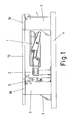
- the seats (1) belonging thereto are arranged in assemblies of several seats (1) fitted on a structural supporting beam (2), said assemblies being mounted in articulated manner on an arrangement of low pillars (3) fixed to the base floor (4) of the relevant enclosed space.
- the seat assemblies (1) are mounted on the pillars (3) by means of a number of arms (5) which are firmly connected to the structural beam (2), said arms (5) being connected to the corresponding mounting pillars (3) by means of an articulation (6).
- each seat assembly (1) may swivel between a lowered position and a raised position, pivoting on the articulations (6) of the arms (5) relative to the pillars (3), a number of gas cylinders (7) being provided to assist with the raising and lowering movements, these additionally cushioning the final strokes of said movements so as to prevent abrupt shocks.
- the catch (8) enters the orifice (12) in the link (11), so bringing about locking, which ensures that the seat assembly (1) is held in said raised position, which is the position of use, preventing said assembly from being able to swivel accidentally downwards as a result of the forces exerted on the seats (1) by users.
- the catch (8) may move backwards, releasing the lock relative to the link (11), the result being that the corresponding seat assembly (1) becomes free and is thus able to be swivelled into the lowered position.
- Each seat assembly (1) may have one or more locking devices, one locking device preferably being provided on each mounting pillar (3) so as reliably to ensure that the seat assembly is held in the raised use position. All the locking devices of each seat assembly (1) are arranged, in such a case, with their levers (10) connected by means of a bar (13), such that acting on the lever (10) of any one of the locking devices brings about actuation of all of them so as to release the seat assembly (1) in order to be able to swivel it downwards.
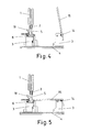
- said flaps (15) form a raised access floor on the pillars (3) of the installation, underneath which are stowed the seat assemblies (1) when said assemblies are in the lowered position, such that in this position the surface of the floor of the enclosed space is totally clear.
- raising the flaps (15) opens up the space for stowing the corresponding seat assemblies (1), it then being possible to swivel said assemblies into the raised position for use of the seats (1), such that, when the seat assemblies (1) are in said raised position, the flaps (15) may swivel back into the lowered position, in which the floor is closed, the supports for the seat assemblies (1) projecting therethrough, said seat assemblies thus being in the position of use above the closed floor.
- the point of articulation (6) of the arms (5) on the pillars (3) of the installation is displaced laterally relative to the longitudinal axis of said arms (5), such that, when the seat assemblies (1) are in the lowered position, the end of the arms (5) is positioned below the respective articulation point (6) , so resulting in an arrangement which allows the system to be compact, with minimal space separating the rows of seats (1) of the installation, and the seat assemblies (1) to be so situated in the lowered position that the covering raised access floor made up of the flaps (15) is positioned at a minimal height relative to the base floor (4).
- the flaps (15) have independent parts (16) which are fastened fixedly to the above-mentioned pillars (3), in such a way that in said areas the flaps (15) define a number of recesses (17), thanks to which the flaps (15) may swivel on the pillars (3) without obstacles arising thereon which would impede said swivelling, as may be seen from the series of Figures 6 to 8 .
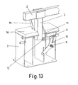
- the above-mentioned fixed parts (16) of the flaps (15) nevertheless have a number of zones (18) which are capable of swivelling, in association with the position of the arms (5) of the support structure of the seat assemblies (1), such that, when said seat assemblies (1) are swivelled into the raised position, the arms (5) force the above-mentioned zones (18) to swivel, said arms (5) thus being able to move out into the raised position as shown in the series of Figures 11 to 13 , whereas, when the seat assemblies (1) are in the concealed position beneath the raised access floor, said zones (18) remain lowered, forming a totally closed surface of the raised access floor, as shown in Figures 6 and 11 .
- the installation formed in this way may be arranged on a horizontal base floor (4), in which case the flaps (15) that form the raised access floor for stowing away the seat assemblies (1) therebelow form a continuous flush surface, as shown in Figure 14 ; however, it is also possible, without modifying essential features, for the installation to be arranged on an inclined base floor (4), in which case the flaps (15) that form the raised access floor may define a stepped surface of horizontal sections, as shown in Figure 15 .
- the seat assemblies (1) together with the associated mounting pillars (3) and the respective flaps (15), take the form of modular assemblies in the manner of structural units, which facilitate mounting of the installation, since it is merely necessary to position said modular assemblies at the sites at which the installation is to be located, it being possible to incorporate the modular assemblies into raised structures so as to adapt the height of the installation as convenient, for example to form stepped tiers of seats capable of being arranged in the position of use or of being cleared away in a concealed arrangement.
- the swivelling arrangement of the seat assemblies (1), as well as of the flaps (15), for movement between the respective lowered and raised positions may be achieved by mounting with manual actuation, but an arrangement with automatic actuation may also be provided, using any motorised, pneumatic or hydraulic system, or any other currently existing system, which permits automation of said swivelling movements of the seat assemblies (1) and of the flaps (15).
Landscapes
- Health & Medical Sciences (AREA)
- Dentistry (AREA)
- General Health & Medical Sciences (AREA)
- Seats For Vehicles (AREA)
- Body Structure For Vehicles (AREA)
- Chairs For Special Purposes, Such As Reclining Chairs (AREA)
Applications Claiming Priority (1)
| Application Number | Priority Date | Filing Date | Title |
|---|---|---|---|
| ES200800496A ES2350130B1 (es) | 2008-02-22 | 2008-02-22 | Instalacion de butacas ocultables bajo el suelo. |
Publications (2)
| Publication Number | Publication Date |
|---|---|
| EP2092854A1 true EP2092854A1 (de) | 2009-08-26 |
| EP2092854B1 EP2092854B1 (de) | 2015-06-17 |
Family
ID=40673339
Family Applications (1)
| Application Number | Title | Priority Date | Filing Date |
|---|---|---|---|
| EP08251474.6A Ceased EP2092854B1 (de) | 2008-02-22 | 2008-04-21 | Im Boden verdeckbare Sitzinstallation |
Country Status (3)
| Country | Link |
|---|---|
| US (1) | US7699388B2 (de) |
| EP (1) | EP2092854B1 (de) |
| ES (1) | ES2350130B1 (de) |
Families Citing this family (6)
| Publication number | Priority date | Publication date | Assignee | Title |
|---|---|---|---|---|
| JP5287301B2 (ja) * | 2009-01-30 | 2013-09-11 | 富士通株式会社 | ディスクリプタ転送装置、i/oコントローラ、及びディスクリプタ転送方法 |
| US10137806B2 (en) | 2015-04-17 | 2018-11-27 | Kyle J Neighbors | Vehicle load floor access panel system |
| US9469349B1 (en) * | 2015-05-22 | 2016-10-18 | Fca Us Llc | Vehicle floor assembly |
| US9352695B1 (en) * | 2015-05-22 | 2016-05-31 | Fca Us Llc | Vehicle floor assembly |
| US10160391B2 (en) | 2017-01-27 | 2018-12-25 | Fca Us Llc | Vehicle floor assembly with electromagnetic latch |
| CN109288291A (zh) * | 2018-09-29 | 2019-02-01 | 北京大倪实业有限公司 | 一种地面隐藏式举臂结构 |
Citations (9)
| Publication number | Priority date | Publication date | Assignee | Title |
|---|---|---|---|---|
| BE400899A (de) * | ||||
| US1173351A (en) * | 1915-04-16 | 1916-02-29 | Thomas E Herington | Chair. |
| GB262140A (en) * | 1925-11-30 | 1927-06-30 | Simon Konstantinowsky | Arrangements for quick transformation of localities used for theatres, cinema-halls and the like, into a suitable dance hall and vice versa |
| FR2545706A1 (fr) * | 1983-05-11 | 1984-11-16 | Vitour Pierre | Systeme de sieges escamotables |
| JPS62281909A (ja) * | 1986-05-30 | 1987-12-07 | カヤバ工業株式会社 | 折り畳み椅子の収納装置 |
| JPH01227708A (ja) * | 1988-03-08 | 1989-09-11 | Kayaba Ind Co Ltd | 折り畳み椅子の収納装置 |
| JPH0311848U (de) * | 1989-06-23 | 1991-02-06 | ||
| FR2659839A1 (fr) * | 1990-03-21 | 1991-09-27 | Rolof Richard | Siege escamotable dans un coffre. |
| CN2631321Y (zh) * | 2003-06-03 | 2004-08-11 | 丰国勋 | 地埋椅 |
Family Cites Families (8)
| Publication number | Priority date | Publication date | Assignee | Title |
|---|---|---|---|---|
| JP2560476B2 (ja) * | 1989-06-09 | 1996-12-04 | 日本電気株式会社 | 通信制御装置 |
| US5195795A (en) * | 1992-04-01 | 1993-03-23 | Cannera Raymond C | Automotive vehicle seat assembly fully retractable below the vehicle's floor |
| CN2231321Y (zh) * | 1995-10-11 | 1996-07-17 | 张庭宝 | 安全摇把 |
| CN1129384C (zh) * | 2000-06-10 | 2003-12-03 | 丰国勋 | 一种排椅翻放定位装置 |
| US7484785B2 (en) * | 2003-06-05 | 2009-02-03 | Intier Automotive Inc. | Automatic tumble and slide vehicle seat assembly |
| US6983985B2 (en) * | 2004-06-07 | 2006-01-10 | Daimlerchrysler Corporation | Seat and storage bin cover assembly |
| FR2877283B1 (fr) * | 2004-10-29 | 2007-01-26 | Faurecia Sieges Automobile | Siege escamotable dans le plancher |
| US7452019B1 (en) * | 2007-06-05 | 2008-11-18 | Toyota Motor Engineering & Manufacturing North America, Inc. | Sliding and stowing motor vehicle seat |
-
2008
- 2008-02-22 ES ES200800496A patent/ES2350130B1/es not_active Expired - Fee Related
- 2008-04-21 EP EP08251474.6A patent/EP2092854B1/de not_active Ceased
- 2008-07-07 US US12/168,262 patent/US7699388B2/en active Active
Patent Citations (9)
| Publication number | Priority date | Publication date | Assignee | Title |
|---|---|---|---|---|
| BE400899A (de) * | ||||
| US1173351A (en) * | 1915-04-16 | 1916-02-29 | Thomas E Herington | Chair. |
| GB262140A (en) * | 1925-11-30 | 1927-06-30 | Simon Konstantinowsky | Arrangements for quick transformation of localities used for theatres, cinema-halls and the like, into a suitable dance hall and vice versa |
| FR2545706A1 (fr) * | 1983-05-11 | 1984-11-16 | Vitour Pierre | Systeme de sieges escamotables |
| JPS62281909A (ja) * | 1986-05-30 | 1987-12-07 | カヤバ工業株式会社 | 折り畳み椅子の収納装置 |
| JPH01227708A (ja) * | 1988-03-08 | 1989-09-11 | Kayaba Ind Co Ltd | 折り畳み椅子の収納装置 |
| JPH0311848U (de) * | 1989-06-23 | 1991-02-06 | ||
| FR2659839A1 (fr) * | 1990-03-21 | 1991-09-27 | Rolof Richard | Siege escamotable dans un coffre. |
| CN2631321Y (zh) * | 2003-06-03 | 2004-08-11 | 丰国勋 | 地埋椅 |
Also Published As
| Publication number | Publication date |
|---|---|
| ES2350130B1 (es) | 2011-09-14 |
| ES2350130A1 (es) | 2011-01-19 |
| US20090212612A1 (en) | 2009-08-27 |
| US7699388B2 (en) | 2010-04-20 |
| EP2092854B1 (de) | 2015-06-17 |
Similar Documents
| Publication | Publication Date | Title |
|---|---|---|
| EP2092854B1 (de) | Im Boden verdeckbare Sitzinstallation | |
| US10508009B2 (en) | Vehicle storage area lift assembly | |
| EP2358237B1 (de) | Entfernbares sitzsystem | |
| CA2315950C (en) | Improved stowable cantilevered seat | |
| EP0012764A1 (de) | Teleskopisches sitzsystem mit automatisch einklappbaren stühlen. | |
| CN101925486A (zh) | 具有直立机构的折叠和跪置式座椅组件 | |
| EP3078594B1 (de) | Verbesserter unterschiedlich konfigurierbarer fahrzeugsitz | |
| KR20090099565A (ko) | 스탠드 업 및 닐 좌석 | |
| JP2020179974A (ja) | 車両用リフト装置 | |
| EP3335931B1 (de) | Ausfahrbare fussstützenanordnung | |
| US5459964A (en) | Stepped grandstands with telescopic elements | |
| US9321378B2 (en) | Vehicle seat | |
| AU2011317690B2 (en) | Vehicle seat | |
| EP4321434B1 (de) | Armlehnenanordnung für einen fahrgastsitz | |
| US8240764B2 (en) | Adjustable vehicle seat suspension assembly | |
| US6588823B1 (en) | Vehicle seat unit | |
| US1763088A (en) | Vehicle construction | |
| WO2017161447A1 (en) | Removable seats system and method of displacing a seat member between operative and concealed positions in a removable seats system | |
| GB2395694A (en) | Trailer/container having pivotal side pillars | |
| RU239081U1 (ru) | Автоматическое парковочное устройство | |
| JP2003227239A (ja) | 移動観覧席用折り畳み式ステップ | |
| WO2018082803A1 (de) | Sitzsystem sowie mit einem derartigen sitzsystem ausgerüsteter saal | |
| KR20180030578A (ko) | 체어 리프트용 체어 | |
| JPH0715951U (ja) | 椅子収納型床装置 | |
| DE2457997A1 (de) | Bettanordnung in schlafwagenabteilen |
Legal Events
| Date | Code | Title | Description |
|---|---|---|---|
| PUAI | Public reference made under article 153(3) epc to a published international application that has entered the european phase |
Free format text: ORIGINAL CODE: 0009012 |
|
| AK | Designated contracting states |
Kind code of ref document: A1 Designated state(s): AT BE BG CH CY CZ DE DK EE ES FI FR GB GR HR HU IE IS IT LI LT LU LV MC MT NL NO PL PT RO SE SI SK TR |
|
| AX | Request for extension of the european patent |
Extension state: AL BA MK RS |
|
| 17P | Request for examination filed |
Effective date: 20100210 |
|
| AKX | Designation fees paid |
Designated state(s): DE FR GB IT |
|
| 17Q | First examination report despatched |
Effective date: 20120910 |
|
| RAP1 | Party data changed (applicant data changed or rights of an application transferred) |
Owner name: FIGUERAS INTERNATIONAL SEATING S.L. |
|
| GRAP | Despatch of communication of intention to grant a patent |
Free format text: ORIGINAL CODE: EPIDOSNIGR1 |
|
| INTG | Intention to grant announced |
Effective date: 20141029 |
|
| GRAS | Grant fee paid |
Free format text: ORIGINAL CODE: EPIDOSNIGR3 |
|
| RIN1 | Information on inventor provided before grant (corrected) |
Inventor name: FIGURERAS MITJANS, JOSE |
|
| GRAA | (expected) grant |
Free format text: ORIGINAL CODE: 0009210 |
|
| AK | Designated contracting states |
Kind code of ref document: B1 Designated state(s): DE FR GB IT |
|
| REG | Reference to a national code |
Ref country code: GB Ref legal event code: FG4D |
|
| REG | Reference to a national code |
Ref country code: DE Ref legal event code: R096 Ref document number: 602008038583 Country of ref document: DE |
|
| REG | Reference to a national code |
Ref country code: DE Ref legal event code: R097 Ref document number: 602008038583 Country of ref document: DE |
|
| REG | Reference to a national code |
Ref country code: FR Ref legal event code: PLFP Year of fee payment: 9 |
|
| PLBE | No opposition filed within time limit |
Free format text: ORIGINAL CODE: 0009261 |
|
| STAA | Information on the status of an ep patent application or granted ep patent |
Free format text: STATUS: NO OPPOSITION FILED WITHIN TIME LIMIT |
|
| 26N | No opposition filed |
Effective date: 20160318 |
|
| REG | Reference to a national code |
Ref country code: FR Ref legal event code: PLFP Year of fee payment: 10 |
|
| REG | Reference to a national code |
Ref country code: FR Ref legal event code: PLFP Year of fee payment: 11 |
|
| PGFP | Annual fee paid to national office [announced via postgrant information from national office to epo] |
Ref country code: DE Payment date: 20220427 Year of fee payment: 15 |
|
| REG | Reference to a national code |
Ref country code: GB Ref legal event code: 732E Free format text: REGISTERED BETWEEN 20221117 AND 20221123 |
|
| P01 | Opt-out of the competence of the unified patent court (upc) registered |
Effective date: 20230523 |
|
| PGFP | Annual fee paid to national office [announced via postgrant information from national office to epo] |
Ref country code: IT Payment date: 20230419 Year of fee payment: 16 Ref country code: FR Payment date: 20230425 Year of fee payment: 16 |
|
| PGFP | Annual fee paid to national office [announced via postgrant information from national office to epo] |
Ref country code: GB Payment date: 20230427 Year of fee payment: 16 |
|
| REG | Reference to a national code |
Ref country code: DE Ref legal event code: R119 Ref document number: 602008038583 Country of ref document: DE |
|
| PG25 | Lapsed in a contracting state [announced via postgrant information from national office to epo] |
Ref country code: DE Free format text: LAPSE BECAUSE OF NON-PAYMENT OF DUE FEES Effective date: 20231103 |
|
| GBPC | Gb: european patent ceased through non-payment of renewal fee |
Effective date: 20240421 |
|
| PG25 | Lapsed in a contracting state [announced via postgrant information from national office to epo] |
Ref country code: GB Free format text: LAPSE BECAUSE OF NON-PAYMENT OF DUE FEES Effective date: 20240421 |
|
| PG25 | Lapsed in a contracting state [announced via postgrant information from national office to epo] |
Ref country code: FR Free format text: LAPSE BECAUSE OF NON-PAYMENT OF DUE FEES Effective date: 20240430 |
|
| PG25 | Lapsed in a contracting state [announced via postgrant information from national office to epo] |
Ref country code: GB Free format text: LAPSE BECAUSE OF NON-PAYMENT OF DUE FEES Effective date: 20240421 Ref country code: FR Free format text: LAPSE BECAUSE OF NON-PAYMENT OF DUE FEES Effective date: 20240430 |
|
| PG25 | Lapsed in a contracting state [announced via postgrant information from national office to epo] |
Ref country code: IT Free format text: LAPSE BECAUSE OF NON-PAYMENT OF DUE FEES Effective date: 20240421 |