EP2092971B1 - Vorrichtung zum Sieben von Bohrschlamm - Google Patents
Vorrichtung zum Sieben von Bohrschlamm Download PDFInfo
- Publication number
- EP2092971B1 EP2092971B1 EP09006866A EP09006866A EP2092971B1 EP 2092971 B1 EP2092971 B1 EP 2092971B1 EP 09006866 A EP09006866 A EP 09006866A EP 09006866 A EP09006866 A EP 09006866A EP 2092971 B1 EP2092971 B1 EP 2092971B1
- Authority
- EP
- European Patent Office
- Prior art keywords
- basket
- feed
- screen
- flow
- filtrate
- Prior art date
- Legal status (The legal status is an assumption and is not a legal conclusion. Google has not performed a legal analysis and makes no representation as to the accuracy of the status listed.)
- Expired - Lifetime
Links
- 238000012216 screening Methods 0.000 title claims abstract description 27
- 238000005553 drilling Methods 0.000 title abstract description 11
- 239000007787 solid Substances 0.000 claims abstract description 30
- 230000000712 assembly Effects 0.000 claims abstract description 25
- 238000000429 assembly Methods 0.000 claims abstract description 25
- 239000000706 filtrate Substances 0.000 claims abstract description 23
- 230000003068 static effect Effects 0.000 claims description 13
- 239000007788 liquid Substances 0.000 claims description 12
- 239000000203 mixture Substances 0.000 claims description 12
- 238000012545 processing Methods 0.000 claims description 10
- 230000037361 pathway Effects 0.000 claims 2
- 239000012530 fluid Substances 0.000 abstract description 35
- 230000015572 biosynthetic process Effects 0.000 description 4
- 238000005755 formation reaction Methods 0.000 description 4
- 239000002245 particle Substances 0.000 description 4
- 230000000717 retained effect Effects 0.000 description 4
- 230000008901 benefit Effects 0.000 description 3
- VTYYLEPIZMXCLO-UHFFFAOYSA-L Calcium carbonate Chemical compound [Ca+2].[O-]C([O-])=O VTYYLEPIZMXCLO-UHFFFAOYSA-L 0.000 description 2
- 238000000034 method Methods 0.000 description 2
- 238000011144 upstream manufacturing Methods 0.000 description 2
- 238000013459 approach Methods 0.000 description 1
- 229910000019 calcium carbonate Inorganic materials 0.000 description 1
- 230000008878 coupling Effects 0.000 description 1
- 238000010168 coupling process Methods 0.000 description 1
- 238000005859 coupling reaction Methods 0.000 description 1
- 238000005520 cutting process Methods 0.000 description 1
- 230000003247 decreasing effect Effects 0.000 description 1
- 238000006073 displacement reaction Methods 0.000 description 1
- 238000001035 drying Methods 0.000 description 1
- 229910052500 inorganic mineral Inorganic materials 0.000 description 1
- 238000012423 maintenance Methods 0.000 description 1
- 239000000463 material Substances 0.000 description 1
- 239000011707 mineral Substances 0.000 description 1
- 238000012986 modification Methods 0.000 description 1
- 230000004048 modification Effects 0.000 description 1
- 239000011236 particulate material Substances 0.000 description 1
- 239000011148 porous material Substances 0.000 description 1
- 230000008569 process Effects 0.000 description 1
- 150000003839 salts Chemical class 0.000 description 1
Images


Classifications
-
- E—FIXED CONSTRUCTIONS
- E21—EARTH OR ROCK DRILLING; MINING
- E21B—EARTH OR ROCK DRILLING; OBTAINING OIL, GAS, WATER, SOLUBLE OR MELTABLE MATERIALS OR A SLURRY OF MINERALS FROM WELLS
- E21B21/00—Methods or apparatus for flushing boreholes, e.g. by use of exhaust air from motor
- E21B21/06—Arrangements for treating drilling fluids outside the borehole
- E21B21/063—Arrangements for treating drilling fluids outside the borehole by separating components
- E21B21/065—Separating solids from drilling fluids
-
- B—PERFORMING OPERATIONS; TRANSPORTING
- B01—PHYSICAL OR CHEMICAL PROCESSES OR APPARATUS IN GENERAL
- B01D—SEPARATION
- B01D33/00—Filters with filtering elements which move during the filtering operation
- B01D33/01—Filters with filtering elements which move during the filtering operation with translationally moving filtering elements, e.g. pistons
- B01D33/03—Filters with filtering elements which move during the filtering operation with translationally moving filtering elements, e.g. pistons with vibrating filter elements
- B01D33/0307—Filters with filtering elements which move during the filtering operation with translationally moving filtering elements, e.g. pistons with vibrating filter elements with bag, cage, hose, tube, sleeve or the like filtering elements
- B01D33/033—Filters with filtering elements which move during the filtering operation with translationally moving filtering elements, e.g. pistons with vibrating filter elements with bag, cage, hose, tube, sleeve or the like filtering elements arranged for outward flow filtration
- B01D33/0338—Filters with filtering elements which move during the filtering operation with translationally moving filtering elements, e.g. pistons with vibrating filter elements with bag, cage, hose, tube, sleeve or the like filtering elements arranged for outward flow filtration open ended
-
- B—PERFORMING OPERATIONS; TRANSPORTING
- B01—PHYSICAL OR CHEMICAL PROCESSES OR APPARATUS IN GENERAL
- B01D—SEPARATION
- B01D33/00—Filters with filtering elements which move during the filtering operation
- B01D33/01—Filters with filtering elements which move during the filtering operation with translationally moving filtering elements, e.g. pistons
- B01D33/03—Filters with filtering elements which move during the filtering operation with translationally moving filtering elements, e.g. pistons with vibrating filter elements
- B01D33/0346—Filters with filtering elements which move during the filtering operation with translationally moving filtering elements, e.g. pistons with vibrating filter elements with flat filtering elements
- B01D33/0376—Filters with filtering elements which move during the filtering operation with translationally moving filtering elements, e.g. pistons with vibrating filter elements with flat filtering elements supported
-
- B—PERFORMING OPERATIONS; TRANSPORTING
- B01—PHYSICAL OR CHEMICAL PROCESSES OR APPARATUS IN GENERAL
- B01D—SEPARATION
- B01D33/00—Filters with filtering elements which move during the filtering operation
- B01D33/35—Filters with filtering elements which move during the filtering operation with multiple filtering elements characterised by their mutual disposition
- B01D33/37—Filters with filtering elements which move during the filtering operation with multiple filtering elements characterised by their mutual disposition in parallel connection
- B01D33/39—Filters with filtering elements which move during the filtering operation with multiple filtering elements characterised by their mutual disposition in parallel connection concentrically or coaxially
-
- B—PERFORMING OPERATIONS; TRANSPORTING
- B07—SEPARATING SOLIDS FROM SOLIDS; SORTING
- B07B—SEPARATING SOLIDS FROM SOLIDS BY SIEVING, SCREENING, SIFTING OR BY USING GAS CURRENTS; SEPARATING BY OTHER DRY METHODS APPLICABLE TO BULK MATERIAL, e.g. LOOSE ARTICLES FIT TO BE HANDLED LIKE BULK MATERIAL
- B07B1/00—Sieving, screening, sifting, or sorting solid materials using networks, gratings, grids, or the like
- B07B1/46—Constructional details of screens in general; Cleaning or heating of screens
-
- B—PERFORMING OPERATIONS; TRANSPORTING
- B07—SEPARATING SOLIDS FROM SOLIDS; SORTING
- B07B—SEPARATING SOLIDS FROM SOLIDS BY SIEVING, SCREENING, SIFTING OR BY USING GAS CURRENTS; SEPARATING BY OTHER DRY METHODS APPLICABLE TO BULK MATERIAL, e.g. LOOSE ARTICLES FIT TO BE HANDLED LIKE BULK MATERIAL
- B07B13/00—Grading or sorting solid materials by dry methods, not otherwise provided for; Sorting articles otherwise than by indirectly controlled devices
- B07B13/14—Details or accessories
- B07B13/16—Feed or discharge arrangements
Definitions
- the present invention relates to vibratory screening apparatus suitable for use with drilling fluids, mineral processing, classification, and dewatering, and the like.
- an initial screen assembly with a mesh size of around 10 to 80 (wires per inch), for example, about 20, and the first and second screen assemblies would have a mesh size of around 40 to 325, conveniently 100 to 250 for example about 200.
- the feed is passed only through the initial coarse screen.
- Fig. 1 shows schematically one embodiment of a vibratory screen apparatus 1 of the invention with an outer housing (indicated schematically) 2, in which is mounted on springs 3, a basket 4.
- the basket is generally box shaped with pairs of circumferentially extending inwardly projecting flanges 5 height on the basket side walls 6, for supporting respective ones of a stack 7 of screen assemblies 8 separated by flow directing trays 9.
- a vibrator unit 10 is secured to the top 11 of the basket. (Alternatively, the vibrator 10 could be mounted on a side of the basket 4, or incorporated into or within the structure of the basket 4.
- the interior 12 of the basket 4 is divided into a series of levels 13 between neighbouring screen assemblies 8 and flow directing trays 9.
- Figs 2A /B, 3A/B and 4A/B show different configurations of the distributor 15 for providing different feed flow arrangements through the screen assemblies 8, which are indicated as A, B and C, respectively, in Figs 2 to 5 .
- FIG 2A shows the inside passage 17 and interior 12 of the basket 14, with an upper flap valve 20' raised to open an upper connecting opening 19' connecting the passage 17 and first level 13 1 above the upper flow deflector tray 9'.
- An intermediate flap valve 20'' is raised to close an intermediate connecting opening 19'' connecting the passage 17 and second level 13 2 between the upper and lower flow deflector trays 9', 9'' whilst simultaneously opening an intermediate level opening 21' in passage 17.
- a lower flap valve 20''' is lowered to open a lower connecting opening 19''' connecting the passage 17 and a fourth level 134 below the lower flow deflector tray 9''.
- Fig. 4A shows the distributor in the inside passage 17 configured so that the upper flap valve 20' is raised as before.
- the intermediate flap valve 20" is lowered so as to open the intermediate connecting opening 19'' whilst simultaneously closing the intermediate level passage opening 21' and the lower flap 20''' is raised to close the lower connecting opening 19''' whilst opening the bottom passage opening 21'''.
- That part 23' of the filtrate 23 from the coarse screen 8' passing into the inside passage 17, is directed onto the first screen 8'' and then out of the bottom opening 21'' of the inside passage 17, by-passing the second screen 8'''.
- the outside passage 18 is configured as in Fig.
- That part 38 of the fluid 33 retained on the second screen 36 is passed through the second deck screen 36 (the solid particulate material 49 retained thereon being "walked up” the screen 36 in the usual way - see Fig. 8B ), as indicated by the double headed arrows 50.
- This part 50 of the fluid flow 33 is then passed through a second deck end wall opening 51 and down a central vertically extending conduit 52 underneath the deflector plates 43.
- a closure panel 53 seals a third deck end wall opening 54, below the second deck end wall opening 51, thereby preventing this part 50 of the fluid flow 33 from entering the third deck 47.
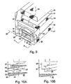
- the module 28 as described above, may be readily reconfigured for serial operation whereby the whole of the fluid is passes through each one of the first, second and third deck screens, 31, 36, 46, as shown in Figs. 9-10 .
- the weir 39 is replaced by a high wall 57 which ensures that the whole of the fluid flow 33 is passed through the second deck screen 36.
- the fluid flow 58 then passes out through the second deck end wall opening 51 into the central vertical conduit 52.
- the bottom opening 55 is sealed by a closure plate 59 whilst the closure panel 53 of the third deck end wall opening 54 is opened so that the fluid flow 58 is routed from the central vertical conduit 52 into the third deck 47 and passed through the screen 46 thereof into the sump 56.
- Figs 11 to 13 show a vibratory screening apparatus 1 of the invention with a generally conventional form of static outer housing 2, in which is mounted on springs 3, and a basket 4 with a vibrator device 10.
- the static housing 2 has a base support 60 which includes a sump 61 for receiving filtrate 62 from the basket 4, and a feed device support portion 63 mounting a feed device 64.
- the feed device 64 comprises a header tank 65 for receiving a liquid and solids mixture feed 66, and having a feed chute 67 extending out therefrom above the basket 4 so as to pass said feed 66 into the basket 4.
- a static flow distributor 24 mounted on the header tank portion 65 of the static housing 2, and coupled to the floating basket 4 via flexible conduits 26.
- the flow distributor 15 is incorporated in the floating basket 4.
Landscapes
- Chemical Kinetics & Catalysis (AREA)
- Engineering & Computer Science (AREA)
- Chemical & Material Sciences (AREA)
- Geology (AREA)
- Mining & Mineral Resources (AREA)
- Life Sciences & Earth Sciences (AREA)
- General Life Sciences & Earth Sciences (AREA)
- Fluid Mechanics (AREA)
- Environmental & Geological Engineering (AREA)
- Physics & Mathematics (AREA)
- Mechanical Engineering (AREA)
- Geochemistry & Mineralogy (AREA)
- Combined Means For Separation Of Solids (AREA)
- Filtration Of Liquid (AREA)
- Separation Of Solids By Using Liquids Or Pneumatic Power (AREA)
- Fertilizers (AREA)
- Treatment Of Sludge (AREA)
- Investigation Of Foundation Soil And Reinforcement Of Foundation Soil By Compacting Or Drainage (AREA)
- Earth Drilling (AREA)
- Non-Silver Salt Photosensitive Materials And Non-Silver Salt Photography (AREA)
- Eye Examination Apparatus (AREA)
- Noodles (AREA)
- Drilling And Exploitation, And Mining Machines And Methods (AREA)
Claims (15)
- Korb (4), geeignet für eine Verwendung in einer Vibrationssiebvorrichtung (1), zur Verwendung beim Entfernen von Feststoffen aus einem zugeführten Gemisch aus Flüssigkeit und Feststoffen, wobei der Korb (4) einen Stapel von wenigstens drei Siebbaugruppen (8', 8", 8''') anbringt, wobei die aufeinandergeschichteten Siebbaugruppen durch einen jeweiligen Durchfluss-Leitboden (9', 9") voneinander getrennt sind,
wobei der Stapel von wenigstens drei Siebbaugruppen (8', 8", 8''') mit einem Durchflussverteiler (15) versehen ist, der so geformt und angeordnet ist, dass er zwischen mehreren unterschiedlichen Durchfluss-Leitkonfigurationen umgeschaltet werden kann, einschließlich von:a) einer Parallelverarbeitungskonfiguration, bei welcher der Durchflussverteiler ein Filtrat von einer primären oberen Siebbaugruppe (8') empfängt und das Filtrat in wenigstens einen ersten Zufuhrstrom und einen zweiten Zufuhrstrom teilt, die Zufuhrströme auf eine jeweilige der ersten (8'') bzw, der zweiten (8''') Siebbaugruppe leitet und das Filtrat von den jeweiligen Durchfluss-Leitböden (9") empfängt, undb) einer Intensivsiebungskonfiguration, bei der die Gesamtheit des Filtrats von einer primären oberen Siebbaugruppe (8') auf eine erste Siebbaugruppe (8'') geleitet wird und die Gesamtheit des Filtrats von der ersten Siebbaugruppe auf eine zweite Siebbaugruppe (8''') geleitet wird. - Korb (4) nach Anspruch 1, wobei die mehreren Durchfluss-Leitkonfigurationen eine Konfiguration mit eingeschränkter Zufuhrkapazität einschließen, bei der die Gesamtheit der Zufuhr auf nur eine von der ersten (8'') und der zweiten (8''') Siebbaugruppe geleitet wird und wobei das Filtrat von derselben ummittelbar aus der Vorrichtung (1) abgelassen wird, ohne durch die andere von der ersten und der zweiten Siebbaugruppe (8'',8''') hindurchzugehen.
- Korb nach Anspruch 1 oder Anspruch 2, wobei wenigstens die primäre Siebbaugruppe (8') eine Maschengröße hat, die sich von wenigstens einer anderen Siebbaugruppe (8",8''') unterscheidet.
- Korb nach einem der Ansprüche 1 bis 3, wobei die erste und die zweite Siebbaugruppe (8'',8''') die gleiche Maschengröße haben.
- Korb nach einem der Ansprüche 1 bis 4, wobei der Durchflussverteiler (15) mehrere Durchflusswege definiert, die mit Durchfluss-Regeleinrichtungen (20), für ein selektives Öffnen oder wenigstens teilweises Schließen von unterschiedlichen Durchgängen (17,18), versehen sind.
- Korb nach einem der Ansprüche 1 bis 5, wobei wenigstens eine Durchfluss-Regeleinrichtung (20) aus der Gruppe ausgewählt ist, die im Wesentlichen aus Klappenventilen (20', 20", 20"'), Hülsenschiebern, Kegelventilen und Verschlussplatten besteht.
- Korb nach Anspruch 5, wobei wenigstens eine Durchfluss-Regeleinrichtung (20) aus einem Wehr (39) besteht, das dafür geformt und angeordnet ist, eine Zufuhr in einen ersten Zufuhrstrom, der über das Wehr hinweggeht, und einen zweiten Zufuhrstrom, der nicht über das Wehr hinweggeht, zu teilen.
- Korb nach Anspruch 7, wobei das Wehr (39) ein Wehr mit veränderlicher Höhe umfasst.
- Korb nach einem der Ansprüche 5 bis 8, wobei der Durchflussverteiler (15) wenigstens eine Wand einschließt, die dafür geformt und angeordnet ist, mehrere seitlich benachbarte Durchflusswege zu definieren.
- Korb nach einem der Ansprüche 1 bis 9, wobei der Durchflussverteiler (15) an dem Korb (4) angebracht ist.
- Korb nach einem der Ansprüche 1 bis 9, wobei der Durchflussverteiler (15) durch flexible Leitungen an den Korb (4) gekoppelt ist.
- Korb nach einem der Ansprüche 1 bis 11, wobei die Durchfluss-Leitböden (9', 9") so geformt und angeordnet sind, dass im Wesentlichen die Gesamtheit des Filtrats von einer Siebbaugruppe (8) unmittelbar über den Durchfluss-Leitboden durch denselben abgefangen werden kann, wodurch die Zufuhr durch den Durchflussverteiler (15) im Wesentlichen vollständig in einen ersten und einen zweiten Zufuhrstrom zu einer jeweiligen der ersten bzw. der zweiten Siebbaugruppe (8",8''') geteilt werden kann.
- Vibrationssiebvorrichtung (1) zur Verwendung beim Entfernen von Feststoffen aus einem zugeführten Gemisch aus Flüssigkeit und Feststoffen, wobei die Vorrichtung einen Korb (4) nach Anspruch 1 umfasst und ferner ein feststehendes äußeres Gehäuse (2) umfasst, wobei das Gehäuse Folgendes umfasst: eine Basisstütze (60), die dafür geformt und angeordnet ist, wenigstens einen Korb (4) auf eine schwimmende Weise anzubringen, so dass er, bei Anwendung der Vorrichtung, in Vibration versetzt werden kann durch eine Vibrationseinrichtung (10), die dafür geformt und angeordnet ist, den Korb (4) in Vibration zu versetzen, wobei die Basisstütze (60) einen Sammelbehälter (61) zum Aufnehmen des Filtrats von dem Korb (4) hat und das Gehäuse (2) eine Zufuhreinrichtung (64) hat, die dafür geformt und angeordnet ist, das zugeführte Gemisch aus Flüssigkeit und Feststoffen zu dem in der Basisstütze (60) angebrachten Korb (4) zu leiten.
- Vibrationssiebvorrichtung (1) nach Anspruch 13, wobei der Korb einen Teil einer Mehrkorbbaugruppe bildet, die mehrere der Körbe umfasst, angebracht in dem feststehenden Gehäuse, und wobei das Gehäuse eine Zufuhr-Verteilungseinrichtung hat, die dafür geformt und angeordnet ist, das zugeführte Gemisch aus Flüssigkeit und Feststoffen zu wenigstens einem der mehreren Körbe zu leiten.
- Vibrationssiebvorrichtung (1) nach Anspruch 13, wobei der Korb (4) ferner eine seitliche Trennwand (68) einschließt, die unabhängige Zufuhr-Verarbeitungsmodule (69, 70) definiert, und wobei das Gehäuse eine Zufuhr- Verteilungseinrichtung (71-74) hat, die dafür geformt und angeordnet ist, das zugeführte Gemisch aus Flüssigkeit und Feststoffen zu wenigstens einem der Korbzufuhr-Verarbeitungsmodule (69, 70) zu leiten.
Applications Claiming Priority (3)
| Application Number | Priority Date | Filing Date | Title |
|---|---|---|---|
| GB0313521A GB0313521D0 (en) | 2003-06-12 | 2003-06-12 | Screening apparatus |
| GB0329920A GB0329920D0 (en) | 2003-12-24 | 2003-12-24 | Screening apparatus |
| EP04736760A EP1631367B1 (de) | 2003-06-12 | 2004-06-14 | Siebvorrichtung |
Related Parent Applications (2)
| Application Number | Title | Priority Date | Filing Date |
|---|---|---|---|
| EP04736760.2 Division | 2004-06-14 | ||
| EP04736760A Division EP1631367B1 (de) | 2003-06-12 | 2004-06-14 | Siebvorrichtung |
Publications (3)
| Publication Number | Publication Date |
|---|---|
| EP2092971A1 EP2092971A1 (de) | 2009-08-26 |
| EP2092971B1 true EP2092971B1 (de) | 2011-02-09 |
| EP2092971B2 EP2092971B2 (de) | 2018-06-20 |
Family
ID=33554143
Family Applications (3)
| Application Number | Title | Priority Date | Filing Date |
|---|---|---|---|
| EP09006866.9A Expired - Lifetime EP2092971B2 (de) | 2003-06-12 | 2004-06-14 | Vorrichtung zum Sieben von Bohrschlamm |
| EP04736760A Revoked EP1631367B1 (de) | 2003-06-12 | 2004-06-14 | Siebvorrichtung |
| EP07020020A Revoked EP1900412B1 (de) | 2003-06-12 | 2004-06-14 | Vorrichtung und Verfahren zum Sieben von Bohrschlamm |
Family Applications After (2)
| Application Number | Title | Priority Date | Filing Date |
|---|---|---|---|
| EP04736760A Revoked EP1631367B1 (de) | 2003-06-12 | 2004-06-14 | Siebvorrichtung |
| EP07020020A Revoked EP1900412B1 (de) | 2003-06-12 | 2004-06-14 | Vorrichtung und Verfahren zum Sieben von Bohrschlamm |
Country Status (7)
| Country | Link |
|---|---|
| US (2) | US7740761B2 (de) |
| EP (3) | EP2092971B2 (de) |
| AT (3) | ATE467451T1 (de) |
| DE (3) | DE602004022665D1 (de) |
| DK (1) | DK2092971T4 (de) |
| NO (2) | NO335550B1 (de) |
| WO (1) | WO2004110589A1 (de) |
Families Citing this family (51)
| Publication number | Priority date | Publication date | Assignee | Title |
|---|---|---|---|---|
| US20050242003A1 (en) | 2004-04-29 | 2005-11-03 | Eric Scott | Automatic vibratory separator |
| US8312995B2 (en) | 2002-11-06 | 2012-11-20 | National Oilwell Varco, L.P. | Magnetic vibratory screen clamping |
| US8453844B2 (en) | 2003-06-12 | 2013-06-04 | Axiom Process Ltd. | Screening system |
| WO2004110589A1 (en) | 2003-06-12 | 2004-12-23 | Axiom Process Limited | Screening apparatus |
| MY148992A (en) * | 2005-12-13 | 2013-06-28 | Mi Llc | Vibratory separator |
| US8613360B2 (en) | 2006-09-29 | 2013-12-24 | M-I L.L.C. | Shaker and degasser combination |
| US20080083566A1 (en) | 2006-10-04 | 2008-04-10 | George Alexander Burnett | Reclamation of components of wellbore cuttings material |
| US7947628B2 (en) | 2006-10-24 | 2011-05-24 | M-I L.L.C. | Method of improving solids separation efficiency |
| GB0714391D0 (en) * | 2007-07-24 | 2007-09-05 | Axiom Process Ltd | Vibratory screening apparatus |
| US8622220B2 (en) | 2007-08-31 | 2014-01-07 | Varco I/P | Vibratory separators and screens |
| BRPI0818499B1 (pt) * | 2007-10-08 | 2019-11-12 | Mi Llc | aparelho para distribuição de um fluido de perfuração, peneira vibratória e método de separação de sólidos |
| CN101965437A (zh) * | 2008-03-07 | 2011-02-02 | M-I有限公司 | 流体分配系统 |
| US20090272702A1 (en) * | 2008-04-30 | 2009-11-05 | Cpc Corporation | Process and apparatus for online rejuvenation of contaminated sulfolane solvent |
| GB2461725B (en) | 2008-07-10 | 2012-06-13 | United Wire Ltd | Improved sifting screen |
| US9073104B2 (en) | 2008-08-14 | 2015-07-07 | National Oilwell Varco, L.P. | Drill cuttings treatment systems |
| US8556083B2 (en) * | 2008-10-10 | 2013-10-15 | National Oilwell Varco L.P. | Shale shakers with selective series/parallel flow path conversion |
| US8113356B2 (en) * | 2008-10-10 | 2012-02-14 | National Oilwell Varco L.P. | Systems and methods for the recovery of lost circulation and similar material |
| US9079222B2 (en) * | 2008-10-10 | 2015-07-14 | National Oilwell Varco, L.P. | Shale shaker |
| CN102341565B (zh) * | 2009-03-06 | 2014-12-17 | M-I有限公司 | 井眼加固材料回收 |
| WO2011113132A1 (en) | 2010-03-18 | 2011-09-22 | Daniel Guy Pomerleau | Optimization of vacuum systems and methods for drying drill cuttings |
| AU2013234389B2 (en) * | 2010-04-30 | 2016-02-11 | National Oilwell Varco, L.P. | Apparatus and method for separating solids from a solids laden drilling fluid |
| CN105064939A (zh) * | 2010-05-12 | 2015-11-18 | 波默洛机械公司 | 模块扩展系统及振荡器系统 |
| GB201010731D0 (en) | 2010-06-25 | 2010-08-11 | Bailey Marshall G | Screening methods and apparatus |
| US8869986B2 (en) | 2010-06-25 | 2014-10-28 | Marshall G. Bailey | Screening methods and apparatus |
| CA2811443C (en) * | 2010-09-15 | 2016-01-12 | M-I L.L.C. | Feeder with screen for shaker |
| GB2483698B (en) * | 2010-09-17 | 2016-02-10 | Drilling Solutions Internat Ltd | Apparatus for and method of recovering clean drilling fluid from fluid contaminated with entrained debris |
| GB201106298D0 (en) * | 2011-04-13 | 2011-05-25 | Bailey Marshall G | Screen assembly |
| CA2836411C (en) * | 2011-05-16 | 2015-11-24 | M-I L.L.C. | Multi-deck shaker |
| GB2507932B (en) | 2011-09-02 | 2017-12-13 | Axiom Process Ltd | Vibratory screening apparatus |
| EP2858762B1 (de) * | 2012-06-11 | 2022-03-23 | M-I L.L.C. | Vibrationsabscheidersieb |
| US20140110357A1 (en) * | 2012-10-23 | 2014-04-24 | Accede Energy Services Ltd. | Shaker table with inertial gas/fluid separation means |
| MX2015010882A (es) * | 2013-02-21 | 2016-06-28 | Mi Llc | Agitadores apilados de doble paso y metodos para el uso de los mismos. |
| US9643111B2 (en) | 2013-03-08 | 2017-05-09 | National Oilwell Varco, L.P. | Vector maximizing screen |
| CN103894341A (zh) * | 2014-03-24 | 2014-07-02 | 李阳春 | 一种油菜籽筛选装置 |
| US10081994B2 (en) | 2015-01-30 | 2018-09-25 | Fp Marangoni Inc. | Screened enclosure with vacuum ports for use in a vacuum-based drilling fluid recovery system |
| CN104612608A (zh) * | 2015-01-30 | 2015-05-13 | 张劲南 | 一种新型泥浆固相控制系统及工艺 |
| WO2017048672A1 (en) | 2015-09-14 | 2017-03-23 | M-I L.L.C. | Clip & seal assembly |
| US20170130541A1 (en) * | 2015-11-11 | 2017-05-11 | M-I L.L.C. | Series and parallel separation device |
| BR102016004243B1 (pt) * | 2016-02-26 | 2019-11-05 | Tmsa Tecnologia Em Movimentacao S A | máquina para limpeza de grãos |
| CA2959851C (en) * | 2016-03-03 | 2026-04-07 | Recover Energy Services Inc. | Gas tight shale shaker for enhanced drilling fluid recovery and drilled solids washing |
| CN106423835B (zh) * | 2016-09-30 | 2019-01-08 | 道真仡佬族苗族自治县渝信有机茶叶有限公司 | 绿茶筛选装置 |
| GB201617435D0 (en) * | 2016-10-14 | 2016-11-30 | Bailey Marshall G | Screening apparatus |
| CN107214068A (zh) * | 2017-06-28 | 2017-09-29 | 四川宏升石油技术开发有限责任公司 | 环保型水泥浆体系的加重剂分级设备 |
| EP3930927B1 (de) * | 2019-02-28 | 2023-10-11 | Dieffenbacher Gmbh Maschinen- Und Anlagenbau | Schirm, insbesondere für staubinduzierte explosionen, und vorzugsweise verwendbar in der holzverarbeitenden industrie |
| CN113710381A (zh) * | 2019-02-28 | 2021-11-26 | 迪芬巴赫机械工程有限公司 | 用于刨花板工厂的筛分件 |
| US11224831B1 (en) * | 2019-03-01 | 2022-01-18 | Del Corporation | Retractable shaker dam assembly and method |
| CN112643924B (zh) * | 2020-12-19 | 2022-10-21 | 重庆市金盾橡胶制品有限公司 | 一种高效率橡胶颗粒多级筛分装置 |
| CN112855054B (zh) * | 2021-03-24 | 2024-06-04 | 西南石油大学 | 一种具有清网功能的磁悬浮驱动旋转振动筛 |
| US11858002B1 (en) | 2022-06-13 | 2024-01-02 | Continental Wire Cloth, LLC | Shaker screen assembly with molded support rail |
| GB2701017A (en) * | 2024-03-06 | 2026-04-08 | Ambipar Response Tank Cleaning S/A | A process for cleaning oil tanks and vessels by treating the flotation generated residues and reusing the washing water |
| CN119634223B (zh) * | 2024-12-30 | 2025-11-21 | 宁夏伯特利活性炭有限公司 | 一种活性炭制备用除杂设备及除杂方法 |
Family Cites Families (47)
| Publication number | Priority date | Publication date | Assignee | Title |
|---|---|---|---|---|
| US957193A (en) * | 1909-03-20 | 1910-05-10 | Gen Electric | Process of preventing surface oxidation of resistance-conductors. |
| US1995435A (en) | 1931-10-13 | 1935-03-26 | Gustave A Overstrom | Vibrating screen |
| US2329333A (en) | 1941-11-10 | 1943-09-14 | Robert J S Carter | Dewatering screen |
| US2576283A (en) * | 1944-07-28 | 1951-11-27 | Sun Oil Co | Process of separating shale cuttings from drilling mud containing plastering agents |
| US2943679A (en) | 1955-07-15 | 1960-07-05 | Pan American Petroleum Corp | Well-servicing compositions and methods |
| US2901109A (en) * | 1957-11-20 | 1959-08-25 | Buehler Ag Geb | Plansifter compartment |
| GB957193A (en) | 1960-10-26 | 1964-05-06 | Parker Ltd Frederick | Improvements relating to screens |
| US3221825A (en) * | 1962-03-15 | 1965-12-07 | Homer I Henderson | Well drilling fluid and a method of using same |
| US3425553A (en) * | 1965-10-23 | 1969-02-04 | Matthew John Slovic | Grading apparatus |
| US3452868A (en) * | 1968-04-03 | 1969-07-01 | Sweco Inc | Parallel flow separator |
| CH499344A (de) * | 1968-11-18 | 1970-11-30 | Buehler Ag Geb | Plansichterabteil |
| US3718963A (en) | 1970-11-25 | 1973-03-06 | J Cutts | Method and apparatus for removing screen wire members from multi-level screen deck assemblies |
| US4116288A (en) | 1977-04-18 | 1978-09-26 | The Brandt Company | Method and apparatus for continuously separating lost circulating material from drilling fluid |
| CH641976A5 (de) * | 1979-01-19 | 1984-03-30 | Buehler Ag Geb | Vorrichtung zur trockenen reinigung von getreide. |
| GB2055597B (en) † | 1979-08-09 | 1983-02-23 | Pa Management Consult | Vibratory screening apparatus for screening liquids |
| US4234416A (en) | 1979-08-23 | 1980-11-18 | Rotex, Inc. | Feed stream splitter for multiple deck screening machine |
| US4460022A (en) | 1980-03-10 | 1984-07-17 | Sherrill John B | Warp stop motion with control bar |
| DE3015665C2 (de) * | 1980-04-23 | 1982-07-22 | Gebr. Schmidt, 8432 Beilngries | Sortiervorrichtung |
| US4319991A (en) * | 1980-10-24 | 1982-03-16 | Midwestern Industries, Inc. | Material separating machine |
| US4340469A (en) | 1981-01-23 | 1982-07-20 | Spokane Crusher Mfg. Co. | Vibratory screen apparatus |
| US4735712A (en) | 1982-07-25 | 1988-04-05 | Herren Harold L | Method of producing wear layer on screen rail and screen rail having wear layer so produced |
| US4576713A (en) * | 1984-07-19 | 1986-03-18 | Carter-Day Company | Feed stream splitter for multiple deck screening machine |
| US4634535A (en) * | 1985-03-25 | 1987-01-06 | Lott W Gerald | Drilling mud cleaning method and apparatus |
| DE3520614A1 (de) * | 1985-06-08 | 1986-12-11 | Mogensen Gmbh & Co Kg, 2000 Wedel | Vibrations-siebmaschine mit integrierter verteil- und segregationseinrichtung |
| US4940535A (en) * | 1988-11-28 | 1990-07-10 | Amoco Corporation | Solids flow distribution apparatus |
| DE4210770C2 (de) | 1992-04-01 | 1994-12-01 | Friedhelm Kaufmann | Siebvorrichtung |
| US5341939A (en) | 1993-02-22 | 1994-08-30 | Corrosion Engineering, Inc. | Multiple deck vibrating screen apparatus |
| US5593582A (en) * | 1993-04-19 | 1997-01-14 | Roff, Jr.; John W. | Two for one shale shaker |
| SE507468C2 (sv) | 1993-05-10 | 1998-06-08 | Svedala Arbra Ab | Vibrationssikt |
| US5614094A (en) | 1994-05-13 | 1997-03-25 | Deister Machine Co., Inc. | Vibrating screen unit |
| GB9507371D0 (en) | 1995-04-10 | 1995-05-31 | Rig Technology Ltd | Improved shale shaker |
| US5641070A (en) | 1995-04-26 | 1997-06-24 | Environmental Procedures, Inc. | Shale shaker |
| US5816413A (en) | 1995-09-08 | 1998-10-06 | W.S. Tyler, Canada | Wire screen deck having replaceable modular screen panels |
| EP0932454B1 (de) | 1996-10-15 | 2001-12-12 | Rig Technology Limited | Verbesserte vibrationssiebmaschine |
| GB2318401B (en) | 1996-10-15 | 1999-03-17 | Rig Technology Ltd | Improved vibratory screening machine |
| US6155428A (en) | 1996-10-15 | 2000-12-05 | Rig Technology Limited | Vibratory screening machine |
| US5853583A (en) * | 1997-03-31 | 1998-12-29 | Kem-Tron Technologies, Inc. | Multi-functional linear motion shaker for processing drilling mud |
| US6024228A (en) | 1997-10-09 | 2000-02-15 | Tuboscope Nu-Tec/Gnt | Bypass diverter box for drilling mud separation unit |
| US6179128B1 (en) | 1998-10-02 | 2001-01-30 | Tuboscope I/P, Inc. | Tension clamp and screen system |
| US6530482B1 (en) † | 2000-04-26 | 2003-03-11 | Michael D. Wiseman | Tandem shale shaker |
| CA2322304C (en) * | 2000-10-04 | 2009-01-27 | Surface To Surface Inc. | Apparatus and method for recycling drilling slurry |
| GB0119523D0 (en) * | 2001-08-10 | 2001-10-03 | Ever 1529 Ltd | Screen system |
| US7111739B2 (en) * | 2002-07-26 | 2006-09-26 | Sizetec, Inc. | Wet fine particle sizing and separating apparatus |
| US7571817B2 (en) * | 2002-11-06 | 2009-08-11 | Varco I/P, Inc. | Automatic separator or shaker with electromagnetic vibrator apparatus |
| US6848583B2 (en) * | 2002-11-27 | 2005-02-01 | Varco I/P, Inc. | Drilling fluid treatment |
| WO2004110589A1 (en) * | 2003-06-12 | 2004-12-23 | Axiom Process Limited | Screening apparatus |
| MY148992A (en) * | 2005-12-13 | 2013-06-28 | Mi Llc | Vibratory separator |
-
2004
- 2004-06-14 WO PCT/GB2004/002544 patent/WO2004110589A1/en not_active Ceased
- 2004-06-14 DE DE602004022665T patent/DE602004022665D1/de not_active Expired - Lifetime
- 2004-06-14 EP EP09006866.9A patent/EP2092971B2/de not_active Expired - Lifetime
- 2004-06-14 DK DK09006866.9T patent/DK2092971T4/en active
- 2004-06-14 DE DE602004031391T patent/DE602004031391D1/de not_active Expired - Lifetime
- 2004-06-14 US US10/561,331 patent/US7740761B2/en not_active Expired - Lifetime
- 2004-06-14 DE DE602004027175T patent/DE602004027175D1/de not_active Expired - Lifetime
- 2004-06-14 AT AT07020020T patent/ATE467451T1/de not_active IP Right Cessation
- 2004-06-14 AT AT04736760T patent/ATE439899T1/de not_active IP Right Cessation
- 2004-06-14 EP EP04736760A patent/EP1631367B1/de not_active Revoked
- 2004-06-14 AT AT09006866T patent/ATE497820T1/de not_active IP Right Cessation
- 2004-06-14 EP EP07020020A patent/EP1900412B1/de not_active Revoked
-
2006
- 2006-01-11 NO NO20060176A patent/NO335550B1/no not_active IP Right Cessation
-
2009
- 2009-07-01 US US12/495,901 patent/US7896162B2/en not_active Expired - Lifetime
- 2009-12-04 NO NO20093476A patent/NO335738B1/no not_active IP Right Cessation
Also Published As
| Publication number | Publication date |
|---|---|
| EP1900412A2 (de) | 2008-03-19 |
| NO335550B1 (no) | 2014-12-29 |
| EP2092971A1 (de) | 2009-08-26 |
| US7896162B2 (en) | 2011-03-01 |
| NO20060176L (no) | 2006-03-06 |
| NO20093476L (no) | 2006-03-06 |
| US20090308819A1 (en) | 2009-12-17 |
| US7740761B2 (en) | 2010-06-22 |
| ATE467451T1 (de) | 2010-05-15 |
| EP2092971B2 (de) | 2018-06-20 |
| EP1900412A3 (de) | 2008-04-23 |
| ATE497820T1 (de) | 2011-02-15 |
| DK2092971T3 (da) | 2011-05-23 |
| DE602004022665D1 (de) | 2009-10-01 |
| US20060144779A1 (en) | 2006-07-06 |
| DE602004031391D1 (de) | 2011-03-24 |
| DE602004027175D1 (de) | 2010-06-24 |
| DK2092971T4 (en) | 2018-10-01 |
| NO335738B1 (no) | 2015-02-02 |
| EP1631367B1 (de) | 2009-08-19 |
| WO2004110589A1 (en) | 2004-12-23 |
| EP1900412B1 (de) | 2010-05-12 |
| ATE439899T1 (de) | 2009-09-15 |
| EP1631367A1 (de) | 2006-03-08 |
Similar Documents
| Publication | Publication Date | Title |
|---|---|---|
| EP2092971B1 (de) | Vorrichtung zum Sieben von Bohrschlamm | |
| US8453844B2 (en) | Screening system | |
| US5853583A (en) | Multi-functional linear motion shaker for processing drilling mud | |
| US6530482B1 (en) | Tandem shale shaker | |
| CN103153488B (zh) | 用于将固体从含有固体的钻井流体分离的泥浆振动筛和方法 | |
| EP1960080B1 (de) | Schwingungsscheider | |
| US10711545B2 (en) | Shale shaker with stair-stepped arrangements of screens and methods of using same, and methods of retrofitting shale shakers | |
| US8807343B2 (en) | Screening method and apparatus | |
| US8869986B2 (en) | Screening methods and apparatus | |
| US20130319955A1 (en) | Screen assembly | |
| WO1996033792A1 (en) | Shale shaker | |
| CN103687677B (zh) | 多筛板振动筛 | |
| CA2348409A1 (en) | A screen for use in a shale shaker and method for using same | |
| NO337845B1 (no) | Fremgangsmåte for å resirkulere faste bestanddeler i et boreslamfluid | |
| AU2013234390B2 (en) | Apparatus and method for separating solids from a solids laden drilling fluid |
Legal Events
| Date | Code | Title | Description |
|---|---|---|---|
| PUAI | Public reference made under article 153(3) epc to a published international application that has entered the european phase |
Free format text: ORIGINAL CODE: 0009012 |
|
| AC | Divisional application: reference to earlier application |
Ref document number: 1631367 Country of ref document: EP Kind code of ref document: P |
|
| AK | Designated contracting states |
Kind code of ref document: A1 Designated state(s): AT BE BG CH CY CZ DE DK EE ES FI FR GB GR HU IE IT LI LU MC NL PL PT RO SE SI SK TR |
|
| 17P | Request for examination filed |
Effective date: 20090824 |
|
| GRAP | Despatch of communication of intention to grant a patent |
Free format text: ORIGINAL CODE: EPIDOSNIGR1 |
|
| GRAS | Grant fee paid |
Free format text: ORIGINAL CODE: EPIDOSNIGR3 |
|
| GRAA | (expected) grant |
Free format text: ORIGINAL CODE: 0009210 |
|
| AC | Divisional application: reference to earlier application |
Ref document number: 1631367 Country of ref document: EP Kind code of ref document: P |
|
| AK | Designated contracting states |
Kind code of ref document: B1 Designated state(s): AT BE BG CH CY CZ DE DK EE ES FI FR GB GR HU IE IT LI LU MC NL PL PT RO SE SI SK TR |
|
| REG | Reference to a national code |
Ref country code: GB Ref legal event code: FG4D |
|
| REG | Reference to a national code |
Ref country code: CH Ref legal event code: EP |
|
| REG | Reference to a national code |
Ref country code: IE Ref legal event code: FG4D |
|
| REF | Corresponds to: |
Ref document number: 602004031391 Country of ref document: DE Date of ref document: 20110324 Kind code of ref document: P |
|
| REG | Reference to a national code |
Ref country code: DE Ref legal event code: R096 Ref document number: 602004031391 Country of ref document: DE Effective date: 20110324 |
|
| REG | Reference to a national code |
Ref country code: DK Ref legal event code: T3 |
|
| REG | Reference to a national code |
Ref country code: NL Ref legal event code: T3 |
|
| PG25 | Lapsed in a contracting state [announced via postgrant information from national office to epo] |
Ref country code: ES Free format text: LAPSE BECAUSE OF FAILURE TO SUBMIT A TRANSLATION OF THE DESCRIPTION OR TO PAY THE FEE WITHIN THE PRESCRIBED TIME-LIMIT Effective date: 20110520 Ref country code: GR Free format text: LAPSE BECAUSE OF FAILURE TO SUBMIT A TRANSLATION OF THE DESCRIPTION OR TO PAY THE FEE WITHIN THE PRESCRIBED TIME-LIMIT Effective date: 20110510 Ref country code: PT Free format text: LAPSE BECAUSE OF FAILURE TO SUBMIT A TRANSLATION OF THE DESCRIPTION OR TO PAY THE FEE WITHIN THE PRESCRIBED TIME-LIMIT Effective date: 20110609 Ref country code: SE Free format text: LAPSE BECAUSE OF FAILURE TO SUBMIT A TRANSLATION OF THE DESCRIPTION OR TO PAY THE FEE WITHIN THE PRESCRIBED TIME-LIMIT Effective date: 20110209 |
|
| PG25 | Lapsed in a contracting state [announced via postgrant information from national office to epo] |
Ref country code: SI Free format text: LAPSE BECAUSE OF FAILURE TO SUBMIT A TRANSLATION OF THE DESCRIPTION OR TO PAY THE FEE WITHIN THE PRESCRIBED TIME-LIMIT Effective date: 20110209 Ref country code: FI Free format text: LAPSE BECAUSE OF FAILURE TO SUBMIT A TRANSLATION OF THE DESCRIPTION OR TO PAY THE FEE WITHIN THE PRESCRIBED TIME-LIMIT Effective date: 20110209 Ref country code: CY Free format text: LAPSE BECAUSE OF FAILURE TO SUBMIT A TRANSLATION OF THE DESCRIPTION OR TO PAY THE FEE WITHIN THE PRESCRIBED TIME-LIMIT Effective date: 20110209 Ref country code: PL Free format text: LAPSE BECAUSE OF FAILURE TO SUBMIT A TRANSLATION OF THE DESCRIPTION OR TO PAY THE FEE WITHIN THE PRESCRIBED TIME-LIMIT Effective date: 20110209 Ref country code: BG Free format text: LAPSE BECAUSE OF FAILURE TO SUBMIT A TRANSLATION OF THE DESCRIPTION OR TO PAY THE FEE WITHIN THE PRESCRIBED TIME-LIMIT Effective date: 20110509 Ref country code: AT Free format text: LAPSE BECAUSE OF FAILURE TO SUBMIT A TRANSLATION OF THE DESCRIPTION OR TO PAY THE FEE WITHIN THE PRESCRIBED TIME-LIMIT Effective date: 20110209 Ref country code: BE Free format text: LAPSE BECAUSE OF FAILURE TO SUBMIT A TRANSLATION OF THE DESCRIPTION OR TO PAY THE FEE WITHIN THE PRESCRIBED TIME-LIMIT Effective date: 20110209 |
|
| PG25 | Lapsed in a contracting state [announced via postgrant information from national office to epo] |
Ref country code: EE Free format text: LAPSE BECAUSE OF FAILURE TO SUBMIT A TRANSLATION OF THE DESCRIPTION OR TO PAY THE FEE WITHIN THE PRESCRIBED TIME-LIMIT Effective date: 20110209 |
|
| PLBI | Opposition filed |
Free format text: ORIGINAL CODE: 0009260 |
|
| PG25 | Lapsed in a contracting state [announced via postgrant information from national office to epo] |
Ref country code: RO Free format text: LAPSE BECAUSE OF FAILURE TO SUBMIT A TRANSLATION OF THE DESCRIPTION OR TO PAY THE FEE WITHIN THE PRESCRIBED TIME-LIMIT Effective date: 20110209 Ref country code: SK Free format text: LAPSE BECAUSE OF FAILURE TO SUBMIT A TRANSLATION OF THE DESCRIPTION OR TO PAY THE FEE WITHIN THE PRESCRIBED TIME-LIMIT Effective date: 20110209 Ref country code: CZ Free format text: LAPSE BECAUSE OF FAILURE TO SUBMIT A TRANSLATION OF THE DESCRIPTION OR TO PAY THE FEE WITHIN THE PRESCRIBED TIME-LIMIT Effective date: 20110209 |
|
| PLAX | Notice of opposition and request to file observation + time limit sent |
Free format text: ORIGINAL CODE: EPIDOSNOBS2 |
|
| 26 | Opposition filed |
Opponent name: OPENSHAW, PAUL MALCOLM Effective date: 20111109 Opponent name: NATIONAL OILWELL VARCO, L.P. Effective date: 20111108 |
|
| REG | Reference to a national code |
Ref country code: CH Ref legal event code: PL |
|
| REG | Reference to a national code |
Ref country code: DE Ref legal event code: R026 Ref document number: 602004031391 Country of ref document: DE Effective date: 20111108 |
|
| REG | Reference to a national code |
Ref country code: IE Ref legal event code: MM4A |
|
| PLAF | Information modified related to communication of a notice of opposition and request to file observations + time limit |
Free format text: ORIGINAL CODE: EPIDOSCOBS2 |
|
| PG25 | Lapsed in a contracting state [announced via postgrant information from national office to epo] |
Ref country code: CH Free format text: LAPSE BECAUSE OF NON-PAYMENT OF DUE FEES Effective date: 20110630 Ref country code: IE Free format text: LAPSE BECAUSE OF NON-PAYMENT OF DUE FEES Effective date: 20110614 Ref country code: LI Free format text: LAPSE BECAUSE OF NON-PAYMENT OF DUE FEES Effective date: 20110630 |
|
| PLBB | Reply of patent proprietor to notice(s) of opposition received |
Free format text: ORIGINAL CODE: EPIDOSNOBS3 |
|
| PLAB | Opposition data, opponent's data or that of the opponent's representative modified |
Free format text: ORIGINAL CODE: 0009299OPPO |
|
| R26 | Opposition filed (corrected) |
Opponent name: NATIONAL OILWELL VARCO, L.P. Effective date: 20111108 Opponent name: OPENSHAW, PAUL MALCOLM Effective date: 20111109 |
|
| PG25 | Lapsed in a contracting state [announced via postgrant information from national office to epo] |
Ref country code: MC Free format text: LAPSE BECAUSE OF NON-PAYMENT OF DUE FEES Effective date: 20110630 |
|
| PG25 | Lapsed in a contracting state [announced via postgrant information from national office to epo] |
Ref country code: LU Free format text: LAPSE BECAUSE OF NON-PAYMENT OF DUE FEES Effective date: 20110614 |
|
| RAP2 | Party data changed (patent owner data changed or rights of a patent transferred) |
Owner name: AXIOM PROCESS LIMITED |
|
| PG25 | Lapsed in a contracting state [announced via postgrant information from national office to epo] |
Ref country code: TR Free format text: LAPSE BECAUSE OF FAILURE TO SUBMIT A TRANSLATION OF THE DESCRIPTION OR TO PAY THE FEE WITHIN THE PRESCRIBED TIME-LIMIT Effective date: 20110209 |
|
| APBM | Appeal reference recorded |
Free format text: ORIGINAL CODE: EPIDOSNREFNO |
|
| APBP | Date of receipt of notice of appeal recorded |
Free format text: ORIGINAL CODE: EPIDOSNNOA2O |
|
| APAH | Appeal reference modified |
Free format text: ORIGINAL CODE: EPIDOSCREFNO |
|
| APBM | Appeal reference recorded |
Free format text: ORIGINAL CODE: EPIDOSNREFNO |
|
| APBP | Date of receipt of notice of appeal recorded |
Free format text: ORIGINAL CODE: EPIDOSNNOA2O |
|
| APAW | Appeal reference deleted |
Free format text: ORIGINAL CODE: EPIDOSDREFNO |
|
| APAY | Date of receipt of notice of appeal deleted |
Free format text: ORIGINAL CODE: EPIDOSDNOA2O |
|
| APBM | Appeal reference recorded |
Free format text: ORIGINAL CODE: EPIDOSNREFNO |
|
| APBP | Date of receipt of notice of appeal recorded |
Free format text: ORIGINAL CODE: EPIDOSNNOA2O |
|
| PG25 | Lapsed in a contracting state [announced via postgrant information from national office to epo] |
Ref country code: HU Free format text: LAPSE BECAUSE OF FAILURE TO SUBMIT A TRANSLATION OF THE DESCRIPTION OR TO PAY THE FEE WITHIN THE PRESCRIBED TIME-LIMIT Effective date: 20110209 |
|
| APBQ | Date of receipt of statement of grounds of appeal recorded |
Free format text: ORIGINAL CODE: EPIDOSNNOA3O |
|
| APBQ | Date of receipt of statement of grounds of appeal recorded |
Free format text: ORIGINAL CODE: EPIDOSNNOA3O |
|
| REG | Reference to a national code |
Ref country code: FR Ref legal event code: PLFP Year of fee payment: 13 |
|
| PLBP | Opposition withdrawn |
Free format text: ORIGINAL CODE: 0009264 |
|
| REG | Reference to a national code |
Ref country code: FR Ref legal event code: PLFP Year of fee payment: 14 |
|
| APBU | Appeal procedure closed |
Free format text: ORIGINAL CODE: EPIDOSNNOA9O |
|
| REG | Reference to a national code |
Ref country code: FR Ref legal event code: PLFP Year of fee payment: 15 |
|
| PUAH | Patent maintained in amended form |
Free format text: ORIGINAL CODE: 0009272 |
|
| STAA | Information on the status of an ep patent application or granted ep patent |
Free format text: STATUS: PATENT MAINTAINED AS AMENDED |
|
| 27A | Patent maintained in amended form |
Effective date: 20180620 |
|
| AK | Designated contracting states |
Kind code of ref document: B2 Designated state(s): AT BE BG CH CY CZ DE DK EE ES FI FR GB GR HU IE IT LI LU MC NL PL PT RO SE SI SK TR |
|
| REG | Reference to a national code |
Ref country code: DE Ref legal event code: R102 Ref document number: 602004031391 Country of ref document: DE |
|
| REG | Reference to a national code |
Ref country code: DK Ref legal event code: T4 Effective date: 20180926 |
|
| REG | Reference to a national code |
Ref country code: NL Ref legal event code: FP |
|
| PGFP | Annual fee paid to national office [announced via postgrant information from national office to epo] |
Ref country code: FR Payment date: 20200512 Year of fee payment: 17 |
|
| PGFP | Annual fee paid to national office [announced via postgrant information from national office to epo] |
Ref country code: IT Payment date: 20200512 Year of fee payment: 17 Ref country code: NL Payment date: 20200615 Year of fee payment: 17 |
|
| REG | Reference to a national code |
Ref country code: DE Ref legal event code: R082 Ref document number: 602004031391 Country of ref document: DE Representative=s name: MARKS & CLERK (LUXEMBOURG) LLP, LU Ref country code: DE Ref legal event code: R081 Ref document number: 602004031391 Country of ref document: DE Owner name: NATIONAL OILWELL VARCO UK LIMITED, GB Free format text: FORMER OWNER: AXIOM PROCESS LTD., NEWCASTLE UPON TYNE, GB |
|
| REG | Reference to a national code |
Ref country code: GB Ref legal event code: 732E Free format text: REGISTERED BETWEEN 20210624 AND 20210630 |
|
| PGFP | Annual fee paid to national office [announced via postgrant information from national office to epo] |
Ref country code: GB Payment date: 20210728 Year of fee payment: 18 |
|
| REG | Reference to a national code |
Ref country code: NL Ref legal event code: PD Owner name: NATIONAL OILWELL VARCO UK LIMITED; GB Free format text: DETAILS ASSIGNMENT: CHANGE OF OWNER(S), ASSIGNMENT; FORMER OWNER NAME: AXIOM PROCESS LIMITED Effective date: 20211110 |
|
| REG | Reference to a national code |
Ref country code: NL Ref legal event code: MM Effective date: 20210701 |
|
| PG25 | Lapsed in a contracting state [announced via postgrant information from national office to epo] |
Ref country code: NL Free format text: LAPSE BECAUSE OF NON-PAYMENT OF DUE FEES Effective date: 20210701 Ref country code: FR Free format text: LAPSE BECAUSE OF NON-PAYMENT OF DUE FEES Effective date: 20210630 |
|
| PG25 | Lapsed in a contracting state [announced via postgrant information from national office to epo] |
Ref country code: IT Free format text: LAPSE BECAUSE OF NON-PAYMENT OF DUE FEES Effective date: 20210614 |
|
| GBPC | Gb: european patent ceased through non-payment of renewal fee |
Effective date: 20220614 |
|
| PG25 | Lapsed in a contracting state [announced via postgrant information from national office to epo] |
Ref country code: GB Free format text: LAPSE BECAUSE OF NON-PAYMENT OF DUE FEES Effective date: 20220614 |
|
| PGFP | Annual fee paid to national office [announced via postgrant information from national office to epo] |
Ref country code: DK Payment date: 20230613 Year of fee payment: 20 Ref country code: DE Payment date: 20230418 Year of fee payment: 20 |
|
| REG | Reference to a national code |
Ref country code: DE Ref legal event code: R071 Ref document number: 602004031391 Country of ref document: DE |
|
| REG | Reference to a national code |
Ref country code: DK Ref legal event code: EUP Expiry date: 20240614 |