EP2093412A1 - Dispositif de couplage - Google Patents
Dispositif de couplage Download PDFInfo
- Publication number
- EP2093412A1 EP2093412A1 EP08003044A EP08003044A EP2093412A1 EP 2093412 A1 EP2093412 A1 EP 2093412A1 EP 08003044 A EP08003044 A EP 08003044A EP 08003044 A EP08003044 A EP 08003044A EP 2093412 A1 EP2093412 A1 EP 2093412A1
- Authority
- EP
- European Patent Office
- Prior art keywords
- fuel injector
- ring element
- fuel
- ring
- coupling device
- Prior art date
- Legal status (The legal status is an assumption and is not a legal conclusion. Google has not performed a legal analysis and makes no representation as to the accuracy of the status listed.)
- Granted
Links
Images
Classifications
-
- F—MECHANICAL ENGINEERING; LIGHTING; HEATING; WEAPONS; BLASTING
- F02—COMBUSTION ENGINES; HOT-GAS OR COMBUSTION-PRODUCT ENGINE PLANTS
- F02M—SUPPLYING COMBUSTION ENGINES IN GENERAL WITH COMBUSTIBLE MIXTURES OR CONSTITUENTS THEREOF
- F02M61/00—Fuel-injectors not provided for in groups F02M39/00 - F02M57/00 or F02M67/00
- F02M61/14—Arrangements of injectors with respect to engines; Mounting of injectors
-
- F—MECHANICAL ENGINEERING; LIGHTING; HEATING; WEAPONS; BLASTING
- F02—COMBUSTION ENGINES; HOT-GAS OR COMBUSTION-PRODUCT ENGINE PLANTS
- F02M—SUPPLYING COMBUSTION ENGINES IN GENERAL WITH COMBUSTIBLE MIXTURES OR CONSTITUENTS THEREOF
- F02M55/00—Fuel-injection apparatus characterised by their fuel conduits or their venting means; Arrangements of conduits between fuel tank and pump F02M37/00
- F02M55/02—Conduits between injection pumps and injectors, e.g. conduits between pump and common-rail or conduits between common-rail and injectors
- F02M55/025—Common rails
-
- F—MECHANICAL ENGINEERING; LIGHTING; HEATING; WEAPONS; BLASTING
- F02—COMBUSTION ENGINES; HOT-GAS OR COMBUSTION-PRODUCT ENGINE PLANTS
- F02M—SUPPLYING COMBUSTION ENGINES IN GENERAL WITH COMBUSTIBLE MIXTURES OR CONSTITUENTS THEREOF
- F02M69/00—Low-pressure fuel-injection apparatus ; Apparatus with both continuous and intermittent injection; Apparatus injecting different types of fuel
- F02M69/46—Details, component parts or accessories not provided for in, or of interest apart from, the apparatus covered by groups F02M69/02 - F02M69/44
- F02M69/462—Arrangement of fuel conduits, e.g. with valves for maintaining pressure in the pipes after the engine being shut-down
- F02M69/465—Arrangement of fuel conduits, e.g. with valves for maintaining pressure in the pipes after the engine being shut-down of fuel rails
-
- F—MECHANICAL ENGINEERING; LIGHTING; HEATING; WEAPONS; BLASTING
- F02—COMBUSTION ENGINES; HOT-GAS OR COMBUSTION-PRODUCT ENGINE PLANTS
- F02M—SUPPLYING COMBUSTION ENGINES IN GENERAL WITH COMBUSTIBLE MIXTURES OR CONSTITUENTS THEREOF
- F02M2200/00—Details of fuel-injection apparatus, not otherwise provided for
- F02M2200/16—Sealing of fuel injection apparatus not otherwise provided for
-
- F—MECHANICAL ENGINEERING; LIGHTING; HEATING; WEAPONS; BLASTING
- F02—COMBUSTION ENGINES; HOT-GAS OR COMBUSTION-PRODUCT ENGINE PLANTS
- F02M—SUPPLYING COMBUSTION ENGINES IN GENERAL WITH COMBUSTIBLE MIXTURES OR CONSTITUENTS THEREOF
- F02M2200/00—Details of fuel-injection apparatus, not otherwise provided for
- F02M2200/80—Fuel injection apparatus manufacture, repair or assembly
- F02M2200/8023—Fuel injection apparatus manufacture, repair or assembly the assembly involving use of quick-acting mechanisms, e.g. clips
-
- F—MECHANICAL ENGINEERING; LIGHTING; HEATING; WEAPONS; BLASTING
- F02—COMBUSTION ENGINES; HOT-GAS OR COMBUSTION-PRODUCT ENGINE PLANTS
- F02M—SUPPLYING COMBUSTION ENGINES IN GENERAL WITH COMBUSTIBLE MIXTURES OR CONSTITUENTS THEREOF
- F02M2200/00—Details of fuel-injection apparatus, not otherwise provided for
- F02M2200/85—Mounting of fuel injection apparatus
- F02M2200/856—Mounting of fuel injection apparatus characterised by mounting injector to fuel or common rail, or vice versa
-
- F—MECHANICAL ENGINEERING; LIGHTING; HEATING; WEAPONS; BLASTING
- F02—COMBUSTION ENGINES; HOT-GAS OR COMBUSTION-PRODUCT ENGINE PLANTS
- F02M—SUPPLYING COMBUSTION ENGINES IN GENERAL WITH COMBUSTIBLE MIXTURES OR CONSTITUENTS THEREOF
- F02M2200/00—Details of fuel-injection apparatus, not otherwise provided for
- F02M2200/85—Mounting of fuel injection apparatus
- F02M2200/857—Mounting of fuel injection apparatus characterised by mounting fuel or common rail to engine
Definitions
- the invention relates to a coupling device for hydraulically and mechanically coupling a fuel injector to a fuel rail of a combustion engine.
- Coupling devices for hydraulically and mechanically coupling a fuel injector to a fuel rail are in widespread use, in particular for internal combustion engines.
- Fuel can be supplied to an internal combustion engine by the fuel rail assembly through the fuel injector.
- the fuel injectors can be coupled to the fuel injector cups in different manners.
- Known fuel rails comprise a hollow body with recesses in form of fuel injector cups, wherein the fuel injectors are arranged.
- the connection of the fuel injectors to the fuel injector cups that supply the fuel from a fuel tank via a low or high-pressure fuel pump needs to be very precise to get a correct injection angle and a sealing of the fuel.
- the object of the invention is to create a coupling device for hydraulically and mechanically coupling a fuel injector to a fuel rail which is simply to be manufactured and which facilitates a reliable and precise connection between the fuel injector and the fuel injector cup without a resting of the fuel injector on the cylinder head.
- the invention is distinguished by a coupling device for hydraulically and mechanically coupling a fuel injector to a fuel rail of a combustion engine, the coupling device comprising a fuel injector cup having a central longitudinal axis and being designed to be hydraulically coupled to the fuel rail and to engage a fuel inlet portion of the fuel injector, a first ring element being fixedly coupled to the fuel injector cup, and a second ring element being fixedly coupled to the fuel injector.
- One of the ring elements comprises a collar which is arranged radially outside the other of the ring elements and extends from the one of the ring elements in direction of the central longitudinal axis. The collar has a recess facing the central longitudinal axis.
- a circlip is arranged in the recess and is arranged and designed to form a positive fitting coupling between the first ring element and the second ring element.
- the circlip is designed to prevent a movement of the first ring element relative to the second ring element to retain the fuel injector in the fuel injector cup in direction of the central longitudinal axis.
- the coupling device can resist the high fuel pressures in the fuel injector and the fuel injector cup. Furthermore, the use of internal circlips is possible. Additionally, the coupling of the fuel injector with the fuel rail by the ring elements of the fuel injector and the fuel injector cup allows an assembly of the fuel injector and the fuel rail without a further metallic contact between the fuel injector and further parts of the combustion engine. Consequently, a noise transmission between the fuel injector and further parts of the combustion engine can be kept small.
- the collar is fixedly coupled to the second ring element.
- the fuel injector cup comprises a groove, and a first snap ring is arranged in the groove and is designed to fixedly couple the first ring element to the fuel injector cup. This may allow a simple construction of the coupling device which enables to carry out a fast and secure but reversible coupling of the first ring element to the fuel injector cup.
- the groove and the first snap ring are arranged and designed to form a positive fitting coupling between the first ring element and the fuel injector cup which is designed to prevent a movement of the first ring element relative to the fuel injector cup at least in a first direction of the central longitudinal axis.
- the coupling device has a welding seam which is arranged between the first ring element and the fuel injector cup to fixedly couple the first ring element to the fuel injector cup.
- the first ring element is in one part with the fuel injector cup. This has the advantage that a very secure coupling of the fuel injector to the fuel injector cup is possible. Furthermore, a simple machining of the first ring element together with the fuel injector cup is possible.
- the fuel injector comprises a groove
- a second snap ring is arranged in the groove of the fuel injector and is designed to fixedly couple the second ring element to the fuel injector. This may allow a simple construction of the coupling device which enables to carry out a fast and secure but reversible coupling of the second ring element to the fuel injector.
- the groove of the fuel injector and the second snap ring are arranged and designed to form a positive fitting coupling between the second ring element and the fuel injector which is designed to prevent a movement of the second ring element relative to the fuel injector at least in a second direction of the central longitudinal axis opposing the first direction of the central longitudinal.
- a welding seam is arranged between the second ring element and the fuel injector to fixedly couple the second ring element to the fuel injector.
- the second ring element is in one part with the fuel injector. This has the advantage that a very secure coupling of the fuel injector to the fuel injector cup is possible. Furthermore, a simple machining of the second ring element together with the fuel injector is possible.
- one of the ring elements is designed and arranged to enable a screw coupling between the ring elements.
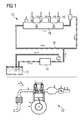
- a fuel feed device 10 is assigned to an internal combustion engine 22 ( figure 1 ) which can be a diesel engine or a gasoline engine. It includes a fuel tank 12 that is connected via a first fuel line to a fuel pump 14. The output of the fuel pump 14 is connected to a fuel inlet 16 of a fuel rail 18. In the fuel rail 18, the fuel is stored for example under a pressure of about 200 bar in the case of a gasoline engine or of about 2,000 bar in the case of a diesel engine. Fuel injectors 20 are connected to the fuel rail 18 and the fuel is fed to the fuel injectors 20 via the fuel rail 18.
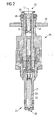
- FIG. 2 shows the fuel injector 20.
- the fuel injector 20 has a fuel injector body 21 and is suitable for injecting fuel into a combustion chamber of the internal combustion engine 22.
- the fuel injector 20 has a fuel inlet portion 24 and a fuel outlet portion 25.
- the fuel injector 20 comprises a valve needle 26 taken in a cavity 29 of the fuel injector body 21.
- an injection nozzle 28 is formed which is closed or opened by an axial movement of the valve needle 26. In a closing position a fuel flow through the injection nozzle 28 is prevented. In an opening position fuel can flow through the injection nozzle 28 into the combustion chamber of the internal combustion engine 22.
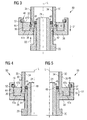
- Figures 3 to 5 show different embodiments of a coupling device 50 which is coupled to the fuel rail 18 of the internal combustion engine 22.
- the coupling device 50 has a fuel injector cup 30, a first ring element 36, a second ring element 38 and a circlip 52.
- the fuel injector cup 30 comprises a central longitudinal axis L, an inner surface 34 and an outer surface 35 and is hydraulically coupled to the fuel rail 18. Furthermore, the fuel injector cup 30 is in engagement with the fuel inlet portion 24 of the fuel injector 20.
- the fuel inlet portion 24 of the fuel injector 20 comprises a sealing ring 48 with an outer surface 49 which is in sealing contact with the inner surface 34 of the fuel injector cup 30.
- the first ring element 36 has a cylindrical shape and is fixedly coupled to the fuel injector cup 30.
- the first ring element 36 has a first contact surface 47a facing the second ring element 38 in axial direction and a second contact surface 47b facing away from the second ring element 38 in axial direction.
- the second ring element 38 has a cylindrical shape and is fixedly coupled to the fuel injector 20.
- the second ring element 38 comprises a collar 44.
- the collar 44 is one piece with the second ring element 38.
- the collar 44 can be a separate part which is fixedly coupled to the second ring element 38.
- the first ring element 36 can comprise the collar 44.
- the collar 44 extends from the second ring element 38 in direction of the central longitudinal axis L.
- the collar 44 has a recess 46 facing the central longitudinal axis L.
- Figure 3 shows an embodiment of the coupling device 50 wherein the fuel injector cup 30 has a groove 32 and the fuel injector 20 has a groove 27.
- the coupling device 50 has a first snap ring 40 which is arranged in the groove 32 of the fuel injector cup 30 and a second snap ring 42 which is arranged in the groove 27 of the fuel injector 20.
- the first ring element 36 is in engagement with the first snap ring 40 and the second ring element 38 is in engagement with the second snap ring 42.
- the first snap ring 40 enables a positive fitting coupling between the first ring element 36 and the fuel injector cup 30 to prevent a movement of the first ring element 36 relative to the fuel injector cup 30 in a first direction D1.
- the second snap ring 42 enables a positive fitting coupling between the second ring element 38 and the fuel injector 20 to prevent a movement of the second ring element 38 relative to the fuel injector 20 in a second direction D2.
- the first direction D1 and the second direction D2 are opposing directions of the central longitudinal axis L.
- the circlip 52 is arranged in the recess 46 and forms a positive fitting coupling between the first ring element 36 and the second ring element 38.
- the circlip 52 prevents a movement of the first ring element 36 relative to the second ring element 38.
- the second ring element 38 is fixedly coupled to the fuel injector 20 and the first ring element 36 is fixedly coupled to the second ring element 38 by the circlip 52, the fuel injector 20 is retained in the fuel injector cup 30 in direction of the central longitudinal axis L.
Landscapes
- Engineering & Computer Science (AREA)
- Chemical & Material Sciences (AREA)
- Combustion & Propulsion (AREA)
- Mechanical Engineering (AREA)
- General Engineering & Computer Science (AREA)
- Fuel-Injection Apparatus (AREA)
Priority Applications (3)
| Application Number | Priority Date | Filing Date | Title |
|---|---|---|---|
| EP08003044A EP2093412B1 (fr) | 2008-02-19 | 2008-02-19 | Dispositif de couplage |
| DE602008004621T DE602008004621D1 (de) | 2008-02-19 | 2008-02-19 | Kupplungsvorrichtung |
| US12/371,708 US8286612B2 (en) | 2008-02-19 | 2009-02-16 | Coupling device |
Applications Claiming Priority (1)
| Application Number | Priority Date | Filing Date | Title |
|---|---|---|---|
| EP08003044A EP2093412B1 (fr) | 2008-02-19 | 2008-02-19 | Dispositif de couplage |
Publications (2)
| Publication Number | Publication Date |
|---|---|
| EP2093412A1 true EP2093412A1 (fr) | 2009-08-26 |
| EP2093412B1 EP2093412B1 (fr) | 2011-01-19 |
Family
ID=39645365
Family Applications (1)
| Application Number | Title | Priority Date | Filing Date |
|---|---|---|---|
| EP08003044A Ceased EP2093412B1 (fr) | 2008-02-19 | 2008-02-19 | Dispositif de couplage |
Country Status (3)
| Country | Link |
|---|---|
| US (1) | US8286612B2 (fr) |
| EP (1) | EP2093412B1 (fr) |
| DE (1) | DE602008004621D1 (fr) |
Cited By (3)
| Publication number | Priority date | Publication date | Assignee | Title |
|---|---|---|---|---|
| EP2375052A1 (fr) * | 2010-04-08 | 2011-10-12 | Continental Automotive GmbH | Ensemble d'injecteur de carburant |
| EP2388468A1 (fr) * | 2010-05-18 | 2011-11-23 | Continental Automotive GmbH | Dispositif de couplage |
| EP2208883B1 (fr) * | 2009-01-19 | 2015-07-22 | Continental Automotive GmbH | Dispositif de couplage |
Families Citing this family (11)
| Publication number | Priority date | Publication date | Assignee | Title |
|---|---|---|---|---|
| EP2093412B1 (fr) | 2008-02-19 | 2011-01-19 | Continental Automotive GmbH | Dispositif de couplage |
| EP2093414B1 (fr) * | 2008-02-19 | 2011-07-20 | Continental Automotive GmbH | Dispositif de couplage |
| DE602008004620D1 (de) * | 2008-02-19 | 2011-03-03 | Continental Automotive Gmbh | Kupplungsvorrichtung |
| EP2093413B1 (fr) * | 2008-02-19 | 2011-01-12 | Continental Automotive GmbH | Dispositif de couplage |
| US9109563B2 (en) * | 2011-03-31 | 2015-08-18 | Denso International America, Inc. | Cradled fuel injector mount assembly |
| US10539105B2 (en) * | 2011-09-08 | 2020-01-21 | Continental Automotive Gmbh | Fuel injector and fuel injector assembly |
| DE102012206890A1 (de) * | 2012-04-26 | 2013-10-31 | Robert Bosch Gmbh | Anordnung mit einem Brennstoffverteiler und mehreren Brennstoffeinspritzventilen |
| US9858058B2 (en) | 2014-03-31 | 2018-01-02 | International Business Machines Corporation | Partition mobility for partitions with extended code |
| USD808789S1 (en) | 2015-01-28 | 2018-01-30 | Eaton Corporation | Valve bracket for mounting fuel system components |
| US11454200B2 (en) * | 2019-11-08 | 2022-09-27 | Delphi Technologies Ip Limited | Fuel system with an arrangement which seals between a fuel injector and a fuel rail socket |
| WO2022014142A1 (fr) * | 2020-07-14 | 2022-01-20 | 日立Astemo株式会社 | Corps accouplé, valeur d'injection de carburant le comprenant, et procédé de fabrication d'un corps accouplé |
Citations (3)
| Publication number | Priority date | Publication date | Assignee | Title |
|---|---|---|---|---|
| FR2637021A1 (fr) * | 1988-09-23 | 1990-03-30 | Peugeot | Dispositif de regulation de la pression du carburant d'un moteur a injection, presentant une grande facilite de montage et de demontage |
| EP1460264A1 (fr) | 2003-03-19 | 2004-09-22 | Peugeot Citroen Automobiles S.A. | Dispositif d'injection de carburant pour moteur à combustion interne, notamment d'un véhicule automobile |
| DE102006042597A1 (de) | 2006-08-31 | 2008-03-20 | GM Global Technology Operations, Inc., Detroit | Isolierungssystem für Komponenten einer Hochdruckkraftstoffzuführung mit Direkteinspritzung und Funkenzündung |
Family Cites Families (67)
| Publication number | Priority date | Publication date | Assignee | Title |
|---|---|---|---|---|
| US749496A (en) * | 1904-01-12 | And herbert stew | ||
| US2950130A (en) * | 1957-09-05 | 1960-08-23 | Schneider Richard | Fluid pressure responsive pipe coupling having identical halves |
| US3260539A (en) * | 1965-02-10 | 1966-07-12 | Donald E Herron | Coupling for fluid conduits |
| US3414297A (en) * | 1965-04-09 | 1968-12-03 | Raphael T Pollia | Pipe coupling containing a detachable flange |
| US3908621A (en) * | 1973-04-25 | 1975-09-30 | Ambac Ind | Hydraulically loaded injector nozzle |
| FI53274A7 (fr) * | 1974-02-22 | 1975-08-23 | Goeran Sundholm | |
| DE2653674A1 (de) * | 1976-11-26 | 1978-06-01 | Bosch Gmbh Robert | Einspritzventil fuer eine brennkraftmaschine |
| DE2829057A1 (de) | 1978-07-01 | 1980-01-10 | Bosch Gmbh Robert | Kraftstoffeinspritzanlage |
| US4213564A (en) * | 1978-07-17 | 1980-07-22 | Hulsing Kenneth L | Fuel injector |
| DE3727797A1 (de) * | 1987-08-20 | 1989-03-02 | Bbc Brown Boveri & Cie | Flanschverbindung |
| JPH0196464A (ja) | 1987-10-07 | 1989-04-14 | Mazda Motor Corp | エンジンの燃料噴射装置 |
| IT8768127A0 (it) * | 1987-12-24 | 1987-12-24 | Weber Srl | Dispositivo di raccordo perfezionato per l alimentazione di un iniettore |
| JPH0754612Y2 (ja) * | 1989-06-06 | 1995-12-18 | 臼井国際産業株式会社 | フユーエルデリバリパイプ |
| DE3919231C2 (de) * | 1989-06-13 | 1997-03-06 | Bosch Gmbh Robert | Kraftstoffeinspritzeinrichtung für Brennkraftmaschinen |
| DE4131537A1 (de) * | 1991-09-21 | 1993-04-01 | Bosch Gmbh Robert | Brennstoffverteiler |
| US5301647A (en) * | 1993-06-14 | 1994-04-12 | Siemens Automotive L.P. | Fuel injector attachment clip |
| KR100301383B1 (ko) * | 1996-07-18 | 2002-07-03 | 오카메 히로무 | 연료분사장치 |
| US5765534A (en) * | 1996-12-10 | 1998-06-16 | Caterpillar Inc. | Loading absorbing jumper tube assembly |
| JP3301354B2 (ja) * | 1996-12-24 | 2002-07-15 | トヨタ自動車株式会社 | 燃料噴射装置 |
| DE19725076A1 (de) * | 1997-06-13 | 1998-12-17 | Bosch Gmbh Robert | Brennstoffeinspritzanlage |
| DE19735665A1 (de) | 1997-06-25 | 1999-01-07 | Bosch Gmbh Robert | Brennstoffeinspritzanlage |
| DE19727543A1 (de) * | 1997-06-28 | 1999-01-07 | Bosch Gmbh Robert | Kraftstoffzuleitungseinrichtung |
| DE19758817B4 (de) * | 1997-12-17 | 2010-08-26 | Dr. Ing. H.C. F. Porsche Aktiengesellschaft | Halterung für ein Brennstoffeinspritzventil am Zylinderkopf einer Brennkraftmaschine |
| GB9727421D0 (en) * | 1997-12-30 | 1998-02-25 | Perkins Ltd | Apparatus and method for connecting a fuel pressure tube to a fuel injector of an internal combustion engine |
| DE19902186A1 (de) * | 1999-01-21 | 2000-07-27 | Bosch Gmbh Robert | Brennstoffeinspritzvorrichtung |
| JP3802702B2 (ja) * | 1999-02-26 | 2006-07-26 | 株式会社ケーヒン | 電磁式燃料噴射弁におけるシール部材の取付け構造 |
| US6227785B1 (en) * | 1999-06-29 | 2001-05-08 | Siemens Automotive Corporation | Self-tightening clip |
| DE19941054A1 (de) * | 1999-08-28 | 2001-03-01 | Bosch Gmbh Robert | Kraftstoffeinspritzventil für Brennkraftmaschinen |
| DE19941770A1 (de) | 1999-09-02 | 2001-03-15 | Bosch Gmbh Robert | Rücklaufeinrichtung |
| ATE269490T1 (de) | 1999-09-10 | 2004-07-15 | Int Engine Intellectual Prop | Betätigungsflüssigkeitsabgabesystem eines kraftstoffeinspritzventils |
| US6394507B1 (en) * | 1999-10-18 | 2002-05-28 | William J. Baker | Apparatus for connecting tubular bodies |
| US6314943B1 (en) * | 1999-10-22 | 2001-11-13 | Ford Global Technologies, Inc. | Fuel supply rail with integrated fuel injector load spring |
| EP1101931B1 (fr) * | 1999-11-19 | 2006-08-30 | CRT Common Rail Technologies AG | Système d'injection à haute pression avec common rail |
| US6830034B2 (en) * | 2000-02-07 | 2004-12-14 | Siemens Automotive Corporation | Fuel injector and fuel rail check valves |
| EP1278956B1 (fr) * | 2000-03-21 | 2005-12-07 | Siemens Aktiengesellschaft | Ensemble injecteur de carburant utilise pour installer un injecteur de carburant sur une rampe de carburant et pour assurer l'alignement de l'injecteur de carburant |
| DE10056038A1 (de) * | 2000-11-11 | 2002-05-16 | Bosch Gmbh Robert | Brennstoffeinspritzanlage |
| US6481420B2 (en) * | 2001-01-30 | 2002-11-19 | Visteon Global Technologies, Inc. | Method and apparatus for maintaining the alignment of a fuel injector |
| DE10108203A1 (de) | 2001-02-21 | 2002-08-29 | Bosch Gmbh Robert | Montagebügel und Verfahren zur Montage eines Brennstoffeinspritzventils |
| DE10136050A1 (de) | 2001-07-25 | 2003-02-13 | Bosch Gmbh Robert | Verfahren zur Herstellung eines Kraftstoffzuteilers mit integrierten Einspritzventilen |
| DE10152421A1 (de) * | 2001-10-24 | 2003-06-18 | Bosch Gmbh Robert | Befestigungsvorrichtung |
| DE10156021A1 (de) * | 2001-11-15 | 2003-06-26 | Bosch Gmbh Robert | Brennstoffeinspritzanlage |
| DE10157010A1 (de) * | 2001-11-21 | 2003-06-05 | Bosch Gmbh Robert | Brennstoffeinspritzanlage |
| US7051961B2 (en) * | 2002-06-07 | 2006-05-30 | Synerject, Llc | Fuel injector with a coating |
| JP3997946B2 (ja) * | 2002-07-26 | 2007-10-24 | 株式会社デンソー | 燃料供給装置 |
| FR2872252B1 (fr) * | 2004-06-25 | 2008-03-14 | Senior Automotive Blois Sas So | Dispositif de connexion |
| US7004151B2 (en) * | 2004-06-29 | 2006-02-28 | Millennium Industries Corp. | Vented injector cup |
| DE102004036626A1 (de) * | 2004-07-29 | 2006-03-23 | Robert Bosch Gmbh | Brennstoffeinspritzsystem |
| DE102004037117B4 (de) | 2004-07-30 | 2013-05-29 | Dr. Ing. H.C. F. Porsche Aktiengesellschaft | Einspritzventil sowie ein Verfahren zur Befestigung dieses Einspritzventils an einer Brennkraftmaschine |
| DE102005020380A1 (de) | 2005-05-02 | 2006-11-09 | Robert Bosch Gmbh | Brennstoffeinspritzvorrichtung |
| EP2187040B1 (fr) * | 2005-03-03 | 2013-01-09 | Robert Bosch GmbH | Dispositif d'injection de carburant |
| DE102005024044A1 (de) | 2005-05-25 | 2006-11-30 | Robert Bosch Gmbh | Vorrichtung zur Befestigung eines Kraftstoff einspritzenden Injektors an einer Brennkraftmaschine |
| US7712797B2 (en) * | 2005-10-07 | 2010-05-11 | Grundfos Pumps Corporation | Universal fluid coupling assembly with interchangeable fitting members |
| DE502006001066D1 (de) * | 2006-01-05 | 2008-08-21 | Norma Germany Gmbh | Verbindungsanordnung mit Rohrstutzen zum Verbinden von Fluidaufnahmeteilen |
| DE602006002803D1 (de) | 2006-02-08 | 2008-10-30 | Siemens Ag | Verbindungsanordnung zum Verbinden eines Injektors mit einer Fluid-Versorgung |
| KR100754501B1 (ko) * | 2007-01-03 | 2007-09-03 | 우양호 | 탈·부착이 용이한 배관의 이음구 |
| US20080169364A1 (en) * | 2007-01-11 | 2008-07-17 | Zdroik Michael J | Welded fuel injector attachment |
| US7445252B2 (en) * | 2007-01-29 | 2008-11-04 | Ying Yeeh Enterprise Co., Ltd. | Connecting device |
| EP1967728B1 (fr) * | 2007-03-08 | 2009-10-14 | Continental Automotive GmbH | Dispositif de couplage et agencement d'alimentation en carburant |
| US7556022B1 (en) * | 2008-01-04 | 2009-07-07 | Millennium Industries | Attachment for fuel injectors in direct injection fuel systems |
| US7516735B1 (en) * | 2008-01-16 | 2009-04-14 | Millennium Industries | Attachment for fuel injectors in a fuel delivery system |
| EP2093414B1 (fr) * | 2008-02-19 | 2011-07-20 | Continental Automotive GmbH | Dispositif de couplage |
| EP2093412B1 (fr) | 2008-02-19 | 2011-01-19 | Continental Automotive GmbH | Dispositif de couplage |
| EP2093413B1 (fr) * | 2008-02-19 | 2011-01-12 | Continental Automotive GmbH | Dispositif de couplage |
| EP2103804B1 (fr) * | 2008-03-19 | 2011-03-02 | Continental Automotive GmbH | Agencement de couplage |
| US20100012093A1 (en) * | 2008-07-18 | 2010-01-21 | Pepperine Dean M | High-pressure fuel injector to fuel rail connection |
| EP2148082B1 (fr) * | 2008-07-24 | 2011-10-19 | Continental Automotive GmbH | Arrangement de couplage pour une soupape d'injection et soupape d'injection |
| KR101344389B1 (ko) * | 2009-02-02 | 2013-12-23 | 테네코 오토모티브 오퍼레이팅 컴파니 인코포레이티드 | 인젝터 탑재 시스템 |
-
2008
- 2008-02-19 EP EP08003044A patent/EP2093412B1/fr not_active Ceased
- 2008-02-19 DE DE602008004621T patent/DE602008004621D1/de active Active
-
2009
- 2009-02-16 US US12/371,708 patent/US8286612B2/en not_active Expired - Fee Related
Patent Citations (3)
| Publication number | Priority date | Publication date | Assignee | Title |
|---|---|---|---|---|
| FR2637021A1 (fr) * | 1988-09-23 | 1990-03-30 | Peugeot | Dispositif de regulation de la pression du carburant d'un moteur a injection, presentant une grande facilite de montage et de demontage |
| EP1460264A1 (fr) | 2003-03-19 | 2004-09-22 | Peugeot Citroen Automobiles S.A. | Dispositif d'injection de carburant pour moteur à combustion interne, notamment d'un véhicule automobile |
| DE102006042597A1 (de) | 2006-08-31 | 2008-03-20 | GM Global Technology Operations, Inc., Detroit | Isolierungssystem für Komponenten einer Hochdruckkraftstoffzuführung mit Direkteinspritzung und Funkenzündung |
Cited By (11)
| Publication number | Priority date | Publication date | Assignee | Title |
|---|---|---|---|---|
| EP2208883B1 (fr) * | 2009-01-19 | 2015-07-22 | Continental Automotive GmbH | Dispositif de couplage |
| EP2375052A1 (fr) * | 2010-04-08 | 2011-10-12 | Continental Automotive GmbH | Ensemble d'injecteur de carburant |
| WO2011124581A1 (fr) * | 2010-04-08 | 2011-10-13 | Continental Automotive Gmbh | Ensemble injecteur de carburant |
| CN102834603A (zh) * | 2010-04-08 | 2012-12-19 | 欧陆汽车有限责任公司 | 燃料喷射器组件 |
| US8905002B2 (en) | 2010-04-08 | 2014-12-09 | Continental Automotive Gmbh | Fuel injector assembly |
| CN102834603B (zh) * | 2010-04-08 | 2014-12-17 | 大陆汽车有限公司 | 燃料喷射器组件 |
| EP2388468A1 (fr) * | 2010-05-18 | 2011-11-23 | Continental Automotive GmbH | Dispositif de couplage |
| WO2011144430A1 (fr) * | 2010-05-18 | 2011-11-24 | Continental Automotive Gmbh | Dispositif de raccord |
| CN102893017A (zh) * | 2010-05-18 | 2013-01-23 | 欧陆汽车有限责任公司 | 联接装置 |
| CN102893017B (zh) * | 2010-05-18 | 2014-09-10 | 大陆汽车有限公司 | 联接装置 |
| US9528485B2 (en) | 2010-05-18 | 2016-12-27 | Continental Automotive Gmbh | Fuel injector coupling device |
Also Published As
| Publication number | Publication date |
|---|---|
| DE602008004621D1 (de) | 2011-03-03 |
| EP2093412B1 (fr) | 2011-01-19 |
| US8286612B2 (en) | 2012-10-16 |
| US20090229576A1 (en) | 2009-09-17 |
Similar Documents
| Publication | Publication Date | Title |
|---|---|---|
| US8286612B2 (en) | Coupling device | |
| EP2093413B1 (fr) | Dispositif de couplage | |
| US7934488B2 (en) | Coupling device | |
| EP2103804B1 (fr) | Agencement de couplage | |
| US7976073B2 (en) | Coupling device | |
| US8245697B2 (en) | Coupling device | |
| EP2375052B1 (fr) | Ensemble d'injecteur de carburant | |
| EP2241746A1 (fr) | Dispositif de couplage | |
| US8875682B2 (en) | Coupling device and fuel injection arrangement | |
| EP2241745B1 (fr) | Dispositif de couplage | |
| EP2058509A1 (fr) | Raccord | |
| EP2112367B1 (fr) | Agencement de couplage et injecteur de carburant | |
| EP2388468B1 (fr) | Dispositif de couplage | |
| US8511280B2 (en) | Coupling device | |
| KR101767353B1 (ko) | 연료 분사기 및 연료 분사 시스템 | |
| EP2090772B1 (fr) | Ensemble de couplage |
Legal Events
| Date | Code | Title | Description |
|---|---|---|---|
| PUAI | Public reference made under article 153(3) epc to a published international application that has entered the european phase |
Free format text: ORIGINAL CODE: 0009012 |
|
| AK | Designated contracting states |
Kind code of ref document: A1 Designated state(s): AT BE BG CH CY CZ DE DK EE ES FI FR GB GR HR HU IE IS IT LI LT LU LV MC MT NL NO PL PT RO SE SI SK TR |
|
| AX | Request for extension of the european patent |
Extension state: AL BA MK RS |
|
| 17P | Request for examination filed |
Effective date: 20100226 |
|
| AKX | Designation fees paid |
Designated state(s): DE FR IT |
|
| GRAP | Despatch of communication of intention to grant a patent |
Free format text: ORIGINAL CODE: EPIDOSNIGR1 |
|
| GRAS | Grant fee paid |
Free format text: ORIGINAL CODE: EPIDOSNIGR3 |
|
| GRAA | (expected) grant |
Free format text: ORIGINAL CODE: 0009210 |
|
| AK | Designated contracting states |
Kind code of ref document: B1 Designated state(s): DE FR IT |
|
| REF | Corresponds to: |
Ref document number: 602008004621 Country of ref document: DE Date of ref document: 20110303 Kind code of ref document: P |
|
| REG | Reference to a national code |
Ref country code: DE Ref legal event code: R096 Ref document number: 602008004621 Country of ref document: DE Effective date: 20110303 |
|
| PLBE | No opposition filed within time limit |
Free format text: ORIGINAL CODE: 0009261 |
|
| STAA | Information on the status of an ep patent application or granted ep patent |
Free format text: STATUS: NO OPPOSITION FILED WITHIN TIME LIMIT |
|
| 26N | No opposition filed |
Effective date: 20111020 |
|
| REG | Reference to a national code |
Ref country code: DE Ref legal event code: R097 Ref document number: 602008004621 Country of ref document: DE Effective date: 20111020 |
|
| REG | Reference to a national code |
Ref country code: FR Ref legal event code: PLFP Year of fee payment: 9 |
|
| REG | Reference to a national code |
Ref country code: FR Ref legal event code: PLFP Year of fee payment: 10 |
|
| REG | Reference to a national code |
Ref country code: FR Ref legal event code: PLFP Year of fee payment: 11 |
|
| PGFP | Annual fee paid to national office [announced via postgrant information from national office to epo] |
Ref country code: DE Payment date: 20180228 Year of fee payment: 11 |
|
| PGFP | Annual fee paid to national office [announced via postgrant information from national office to epo] |
Ref country code: IT Payment date: 20190225 Year of fee payment: 12 |
|
| PGFP | Annual fee paid to national office [announced via postgrant information from national office to epo] |
Ref country code: FR Payment date: 20190220 Year of fee payment: 12 |
|
| REG | Reference to a national code |
Ref country code: DE Ref legal event code: R119 Ref document number: 602008004621 Country of ref document: DE |
|
| PG25 | Lapsed in a contracting state [announced via postgrant information from national office to epo] |
Ref country code: DE Free format text: LAPSE BECAUSE OF NON-PAYMENT OF DUE FEES Effective date: 20190903 |
|
| REG | Reference to a national code |
Ref country code: DE Ref legal event code: R081 Ref document number: 602008004621 Country of ref document: DE Owner name: VITESCO TECHNOLOGIES GMBH, DE Free format text: FORMER OWNER: CONTINENTAL AUTOMOTIVE GMBH, 30165 HANNOVER, DE |
|
| PG25 | Lapsed in a contracting state [announced via postgrant information from national office to epo] |
Ref country code: FR Free format text: LAPSE BECAUSE OF NON-PAYMENT OF DUE FEES Effective date: 20200229 |
|
| PG25 | Lapsed in a contracting state [announced via postgrant information from national office to epo] |
Ref country code: IT Free format text: LAPSE BECAUSE OF NON-PAYMENT OF DUE FEES Effective date: 20200219 |