EP2093830A1 - Antenne pour transpondeur - Google Patents
Antenne pour transpondeur Download PDFInfo
- Publication number
- EP2093830A1 EP2093830A1 EP09075240A EP09075240A EP2093830A1 EP 2093830 A1 EP2093830 A1 EP 2093830A1 EP 09075240 A EP09075240 A EP 09075240A EP 09075240 A EP09075240 A EP 09075240A EP 2093830 A1 EP2093830 A1 EP 2093830A1
- Authority
- EP
- European Patent Office
- Prior art keywords
- antenna
- antenna element
- frame elements
- antenna according
- loop
- Prior art date
- Legal status (The legal status is an assumption and is not a legal conclusion. Google has not performed a legal analysis and makes no representation as to the accuracy of the status listed.)
- Ceased
Links
- 230000005855 radiation Effects 0.000 claims abstract description 21
- 230000000694 effects Effects 0.000 claims abstract description 15
- 239000004033 plastic Substances 0.000 claims abstract description 4
- 230000010287 polarization Effects 0.000 claims description 10
- 244000045947 parasite Species 0.000 claims description 6
- 239000003990 capacitor Substances 0.000 claims description 5
- 230000005684 electric field Effects 0.000 claims description 4
- 239000006260 foam Substances 0.000 claims description 2
- 239000002985 plastic film Substances 0.000 claims description 2
- 229920006255 plastic film Polymers 0.000 claims description 2
- 230000011664 signaling Effects 0.000 claims 2
- 238000004519 manufacturing process Methods 0.000 abstract description 12
- RYGMFSIKBFXOCR-UHFFFAOYSA-N Copper Chemical compound [Cu] RYGMFSIKBFXOCR-UHFFFAOYSA-N 0.000 abstract description 3
- 229910052802 copper Inorganic materials 0.000 abstract description 3
- 239000010949 copper Substances 0.000 abstract description 3
- 239000000463 material Substances 0.000 abstract 1
- 239000003365 glass fiber Substances 0.000 description 3
- 229920001343 polytetrafluoroethylene Polymers 0.000 description 3
- 239000004810 polytetrafluoroethylene Substances 0.000 description 3
- 239000004809 Teflon Substances 0.000 description 2
- 229920006362 Teflon® Polymers 0.000 description 2
- 238000004891 communication Methods 0.000 description 2
- 230000008878 coupling Effects 0.000 description 2
- 238000010168 coupling process Methods 0.000 description 2
- 238000005859 coupling reaction Methods 0.000 description 2
- 239000003989 dielectric material Substances 0.000 description 2
- 239000006261 foam material Substances 0.000 description 2
- 238000005516 engineering process Methods 0.000 description 1
- 230000002349 favourable effect Effects 0.000 description 1
- 238000000034 method Methods 0.000 description 1
- 238000007493 shaping process Methods 0.000 description 1
- 230000001131 transforming effect Effects 0.000 description 1
Images
Classifications
-
- H—ELECTRICITY
- H01—ELECTRIC ELEMENTS
- H01Q—ANTENNAS, i.e. RADIO AERIALS
- H01Q1/00—Details of, or arrangements associated with, antennas
- H01Q1/12—Supports; Mounting means
- H01Q1/22—Supports; Mounting means by structural association with other equipment or articles
- H01Q1/2208—Supports; Mounting means by structural association with other equipment or articles associated with components used in interrogation type services, i.e. in systems for information exchange between an interrogator/reader and a tag/transponder, e.g. in Radio Frequency Identification [RFID] systems
-
- H—ELECTRICITY
- H01—ELECTRIC ELEMENTS
- H01Q—ANTENNAS, i.e. RADIO AERIALS
- H01Q1/00—Details of, or arrangements associated with, antennas
- H01Q1/36—Structural form of radiating elements, e.g. cone, spiral, umbrella; Particular materials used therewith
- H01Q1/38—Structural form of radiating elements, e.g. cone, spiral, umbrella; Particular materials used therewith formed by a conductive layer on an insulating support
Definitions
- the present invention is connected with transponder systems for wireless payment, e.g. for payment of a toll for vehicles.
- Q-Free ASA has manufactured such systems for many years. These systems are used in several countries named as the "Q-free box".
- the expression "box” is related to the transponder element in this system provided in every individual vehicle. The transponder receives data from a device placed near the road, and as an answer it sends individual data back to the road device.
- the technological development within this area has in the meantime moved towards active transponders operating with microwave radiation in the area of 5,8 Hz, that is wavelengths in the area of centimeters, which have a battery and an active communication controller.
- the transponder receives data as amplitude modulated radiation and sends data as phase modulated radiation.
- the simplest embodiment of such a transponder is a diode coupled into an antenna, leading to amplitude demodulation by rectifying the carrier wave.
- a current is sent alternately in the diode, and its reflection coefficient is thus changing, and accordingly this gives phase modulation.
- the principle makes it possible to send without use of a local-oscillator on the transponder and it is known as "back-scattering".
- transponder antennas which have little scattering and which may be produced as simple and cheap as possible.
- microstrip antennas which are easy to manufacture are microstrip antennas. These are antennas which are easily realizable on a substratum together with the rest of the circuitry.
- the problem regarding microstrip antennas is that they are based on resonance where a large e-field concentration along the edge of the antenna element arises towards the earth plane.
- the effectiveness of the antenna and the resonance frequency are very dependant on the dielectric constant in the substratum and the thickness of the substratum. Accordingly, a usual printed circuit board laminate, such as "FR-4" glass fibre laminate, is not suitable for the production of such antennas.
- Good microwave laminate based on PTFE (teflon) is the most common in use, but this laminate is expensive, complicated to manufacture and uses few environmentally friendly processes during the manufacturing.
- the main object of the present invention is to make an antenna of the mentioned kind, that despite of good antenna performances still makes them possible to be manufactured using standard laminate (FR-4), which is suitable for frequencies considerable above 20 GHz, also by volume production of such systems.
- FR-4 standard laminate
- this solution has a considerable advantage compared to known antennas where the direction effect for the antenna extends at least substantially transverse to the plate shaped carrier (the substratum).
- the resonance frequency of the antenna becomes less dependant on the dielectric of the antenna carrier.
- a carrier having a high dielectric quality such as PTFE (teflon)
- the dielectric constant and the dielectric losses of the substratum have little influence on the resonance frequency of the antenna and dielectric losses. This gives little scattering due to volume production and thus it is suitable for products with high production rates.
- Another advantage with regard to the antenna according to the present invention is that it is very broad banded, typically 10 - 20% of the center frequency. Thus, it is very favorable regarding broadband applications.
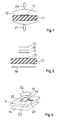
- Fig. 1 shows a part of a printed card or substratum 11 of a dielectric material, for example of glass fibre laminate "FR-4", which is used to manufacture printed circuits.
- the printed card 11 may be in a transponder of the kind mentioned in the introduction and has the function of an antenna supporter, which on its bearing surface 12 supports an antenna element 13.
- the antenna element 13 is connected to a communication controller via an antenna cable (not shown) and is in the present case the excited element in the antenna according to the invention.
- the antenna element is in this embodiment made as a Quad antenna, however, as the antenna element not only consists of a simple, quadratic shaped frame, but consists of two frames 14 and 15 ( fig. 3 ) situated in the same plane, one in the other.
- the frames 14 and 15 are made of copper tracks (not further described) having a fixed width and height, situated in the plane of the bearing surface 12 of the printed card 11.
- the individual frame parts in the two frames 14 and 15, which extend in parallel, have a predetermined mutual distance.
- the circumference of the two frames 14 and 15 may be utilized to achieve a significant directional effect, without additional antenna elements amplifying this effect being necessary, and in size is near the wavelength ⁇ .
- the relatively small difference between the size of the circumferences of the two frames 14 and 15 also means that the resonance frequency of these two frame elements are correspondingly different, such that a certain broad band effect is already achieved through this special combination of two Quad antenna elements.
- This broad band effect may be increased by shaping the two frames 14 and 15 aperiodic.
- a reflector 16 is shown in fig. 2 and 3 , arranged on the opposite side of the printed card 11 compared to the excited antenna element, and having a predetermined distance from this antenna element.
- fig. 2 shows examples of parasite elements or directors 17, 18 and 19, whose purpose is to amplify the directional effect of the antenna, extending across the bearing plane 12 according to the Yagu-Uda principle.
- the arrows 20 and 21, inclusive of the curves lying above and below in fig. 1 symbolizes electrical waves schematically, and illustrate the directional effect intended by the antenna according the invention, consequently extending across the printed card 11.
- the reception and the radiation of the radiation energy in the direction of the arrow 21 is to be suppressed, and instead, the use of a reflector 16 will amplify the radiation in the direction of the arrow 20.
- the directional characteristic which is achieved using the described elements and precautions, has the consequence that the dielectric material in the printed card has no influence on the frequency of the antenna any longer, and that losses arising in the dielectric under influence of the antenna are kept low.
- Fig. 3 shows a polarizer or polarization transformer 22 placed in front of the substratum 11, while the reflector 16 is placed on the back side.
- the polarizer serves to transform the linearly polarized microwave radiation radiated from the antenna element 13 to circular polarized waves, and to transform circular polarized waves received to linearly polarized waves respectively.
- the mentioned antenna elements i.e. the antenna element 13, the reflector 16, the parasite elements 17 to 19 and the polarization transformer 22, are preferably radiation connected to each other via air as the dielectric.
- a foam material having a low dielectric constant and low dielectric losses may also be used, as this foam material then operates as a holder for the different antenna elements.
- the antenna element therefore becomes a resonator having a relatively low Q-factor, preferable a Q-factor between 5 and 10.
- the two branches in the antenna are connected to a coupling capacitor 23 at the connection of the two feeding lines 24.
- a diode 25 connected between the two frames 14, 15 towards the point of connection serves as a receiver rectifying the carrier wave.
- the direct voltage component is laid over the coupling capacitor 23 and is led out over the feeding lines 24.
Landscapes
- Aerials With Secondary Devices (AREA)
- Details Of Aerials (AREA)
- Variable-Direction Aerials And Aerial Arrays (AREA)
- Waveguide Aerials (AREA)
- Radar Systems Or Details Thereof (AREA)
Applications Claiming Priority (2)
| Application Number | Priority Date | Filing Date | Title |
|---|---|---|---|
| NO20000613A NO313975B1 (no) | 2000-02-08 | 2000-02-08 | Antenne for transponder |
| EP01904652A EP1254490A1 (fr) | 2000-02-08 | 2001-01-15 | Antenne pour transpondeur |
Related Parent Applications (1)
| Application Number | Title | Priority Date | Filing Date |
|---|---|---|---|
| EP01904652A Division EP1254490A1 (fr) | 2000-02-08 | 2001-01-15 | Antenne pour transpondeur |
Publications (1)
| Publication Number | Publication Date |
|---|---|
| EP2093830A1 true EP2093830A1 (fr) | 2009-08-26 |
Family
ID=19910700
Family Applications (2)
| Application Number | Title | Priority Date | Filing Date |
|---|---|---|---|
| EP09075240A Ceased EP2093830A1 (fr) | 2000-02-08 | 2001-01-15 | Antenne pour transpondeur |
| EP01904652A Ceased EP1254490A1 (fr) | 2000-02-08 | 2001-01-15 | Antenne pour transpondeur |
Family Applications After (1)
| Application Number | Title | Priority Date | Filing Date |
|---|---|---|---|
| EP01904652A Ceased EP1254490A1 (fr) | 2000-02-08 | 2001-01-15 | Antenne pour transpondeur |
Country Status (10)
| Country | Link |
|---|---|
| US (1) | US6885342B2 (fr) |
| EP (2) | EP2093830A1 (fr) |
| JP (1) | JP4808355B2 (fr) |
| CN (1) | CN1293672C (fr) |
| AU (1) | AU767736B2 (fr) |
| BR (1) | BRPI0108162B1 (fr) |
| CA (1) | CA2399383C (fr) |
| NO (1) | NO313975B1 (fr) |
| WO (1) | WO2001059879A1 (fr) |
| ZA (1) | ZA200205546B (fr) |
Families Citing this family (17)
| Publication number | Priority date | Publication date | Assignee | Title |
|---|---|---|---|---|
| AT411940B (de) * | 2001-12-21 | 2004-07-26 | Efkon Ag | Mobile kommunikations-einrichtung, insbesondere für ein elektronisches gebührenzahlungssystem |
| JP2005340933A (ja) * | 2004-05-24 | 2005-12-08 | Mitsubishi Electric Corp | 円偏波アンテナ、及びこれを用いたレクテナ |
| DE102005010894B4 (de) * | 2005-03-09 | 2008-06-12 | Fraunhofer-Gesellschaft zur Förderung der angewandten Forschung e.V. | Planare Mehrbandantenne |
| US7728785B2 (en) * | 2006-02-07 | 2010-06-01 | Nokia Corporation | Loop antenna with a parasitic radiator |
| JP4287902B2 (ja) | 2007-01-11 | 2009-07-01 | パナソニック株式会社 | 広帯域スロットアンテナ |
| KR20120102173A (ko) * | 2007-09-13 | 2012-09-17 | 퀄컴 인코포레이티드 | 무선 전력 인가를 위한 안테나 |
| EP2141635A1 (fr) * | 2008-06-30 | 2010-01-06 | Nederlandse Organisatie voor toegepast- natuurwetenschappelijk onderzoek TNO | Étiquette de fréquence radio |
| JP5029559B2 (ja) * | 2008-09-30 | 2012-09-19 | 日立電線株式会社 | アンテナ及びそれを備えた電気機器 |
| US8072384B2 (en) * | 2009-01-14 | 2011-12-06 | Laird Technologies, Inc. | Dual-polarized antenna modules |
| US20100314454A1 (en) * | 2009-06-15 | 2010-12-16 | Tc License Ltd. | Configurable external rfid tag |
| US8578599B2 (en) * | 2010-03-22 | 2013-11-12 | Rogers Corporation | Method of making a supported foam circuit laminate |
| US9444147B2 (en) * | 2011-07-18 | 2016-09-13 | The United States Of America As Represented By The Secretary Of The Army | Ultra-wide-band (UWB) antenna assembly with at least one director and electromagnetic reflective subassembly and method |
| CN104332717B (zh) * | 2014-11-27 | 2017-09-15 | 陈念 | 反射器 |
| KR102246561B1 (ko) * | 2019-06-11 | 2021-04-29 | 한양대학교 산학협력단 | 편파 방향을 가변시킬 수 있는 안테나 |
| CN111585006B (zh) * | 2020-05-08 | 2022-04-15 | 武汉虹信科技发展有限责任公司 | 辐射单元及阵列天线 |
| US11417951B2 (en) | 2020-09-01 | 2022-08-16 | Apple Inc. | Electronic devices having antennas that radiate through three-dimensionally curved cover layers |
| CN119965534B (zh) * | 2025-04-11 | 2025-08-08 | 北京理工大学 | 一种基于射频能源俘获的自供电无线传感与通信装置 |
Citations (4)
| Publication number | Priority date | Publication date | Assignee | Title |
|---|---|---|---|---|
| DE2352807A1 (de) * | 1973-10-20 | 1975-04-24 | Philips Patentverwaltung | Sende- und empfangssystem zur erkennung von bewegbaren koerpern |
| EP0344885A2 (fr) * | 1988-05-11 | 1989-12-06 | Amtech Systems Corporation | Antenne réfléchissante |
| US5777470A (en) * | 1994-06-15 | 1998-07-07 | General Microwave Corporation | Broadband probe for detecting the magnetic field component of an electromagnetic field |
| WO1998050977A1 (fr) * | 1997-05-07 | 1998-11-12 | Telefonaktiebolaget Lm Ericsson (Publ) | Antenne bipolarisee et antenne monopolarisee |
Family Cites Families (16)
| Publication number | Priority date | Publication date | Assignee | Title |
|---|---|---|---|---|
| FR2505097A1 (fr) | 1981-05-04 | 1982-11-05 | Labo Electronique Physique | Element rayonnant ou recepteur de signaux hyperfrequences a polarisations circulaires et antenne plane hyperfrequence comprenant un reseau de tels elements |
| GB2142475A (en) * | 1983-06-29 | 1985-01-16 | Decca Ltd | Wide beam microwave antenna |
| JPH01248805A (ja) * | 1988-03-30 | 1989-10-04 | Shigeru Egashira | マイクロストリップアンテナ |
| JPH04115606A (ja) * | 1990-08-31 | 1992-04-16 | Matsushita Electric Works Ltd | 無線装置 |
| US5307075A (en) * | 1991-12-12 | 1994-04-26 | Allen Telecom Group, Inc. | Directional microstrip antenna with stacked planar elements |
| JPH0585112U (ja) * | 1992-04-22 | 1993-11-16 | 顯 神明 | 平行ループアンテナ |
| US5241321A (en) | 1992-05-15 | 1993-08-31 | Space Systems/Loral, Inc. | Dual frequency circularly polarized microwave antenna |
| FR2692404B1 (fr) * | 1992-06-16 | 1994-09-16 | Aerospatiale | Motif élémentaire d'antenne à large bande passante et antenne-réseau le comportant. |
| JP3452971B2 (ja) * | 1994-03-08 | 2003-10-06 | 日本電業工作株式会社 | 偏波可変アンテナ |
| JPH08162831A (ja) * | 1994-12-07 | 1996-06-21 | Kansei Corp | 自動車用キーレスユニットの内蔵アンテナ |
| US5815121A (en) * | 1995-09-15 | 1998-09-29 | Northrop Grumman Corporation | Flatplate array antenna with polarizer lens |
| JP3046233B2 (ja) * | 1995-12-22 | 2000-05-29 | 三菱電機株式会社 | 薄型受信装置並びに送信装置 |
| JPH1022721A (ja) * | 1996-06-28 | 1998-01-23 | Mitsubishi Electric Corp | プリントループアンテナ |
| JPH1084219A (ja) * | 1996-09-06 | 1998-03-31 | Tokimec Inc | 直交2直線偏波アンテナ |
| US5874919A (en) * | 1997-01-09 | 1999-02-23 | Harris Corporation | Stub-tuned, proximity-fed, stacked patch antenna |
| JP2000013131A (ja) * | 1998-06-23 | 2000-01-14 | Harada Ind Co Ltd | 広帯域円偏波ダイポールアンテナ |
-
2000
- 2000-02-08 NO NO20000613A patent/NO313975B1/no not_active IP Right Cessation
-
2001
- 2001-01-15 AU AU32487/01A patent/AU767736B2/en not_active Expired
- 2001-01-15 CA CA2399383A patent/CA2399383C/fr not_active Expired - Lifetime
- 2001-01-15 JP JP2001559097A patent/JP4808355B2/ja not_active Expired - Fee Related
- 2001-01-15 US US10/169,763 patent/US6885342B2/en not_active Expired - Lifetime
- 2001-01-15 WO PCT/NO2001/000013 patent/WO2001059879A1/fr not_active Ceased
- 2001-01-15 EP EP09075240A patent/EP2093830A1/fr not_active Ceased
- 2001-01-15 BR BRPI0108162-4A patent/BRPI0108162B1/pt not_active IP Right Cessation
- 2001-01-15 EP EP01904652A patent/EP1254490A1/fr not_active Ceased
- 2001-01-15 CN CNB018047246A patent/CN1293672C/zh not_active Expired - Lifetime
-
2002
- 2002-07-11 ZA ZA200205546A patent/ZA200205546B/en unknown
Patent Citations (4)
| Publication number | Priority date | Publication date | Assignee | Title |
|---|---|---|---|---|
| DE2352807A1 (de) * | 1973-10-20 | 1975-04-24 | Philips Patentverwaltung | Sende- und empfangssystem zur erkennung von bewegbaren koerpern |
| EP0344885A2 (fr) * | 1988-05-11 | 1989-12-06 | Amtech Systems Corporation | Antenne réfléchissante |
| US5777470A (en) * | 1994-06-15 | 1998-07-07 | General Microwave Corporation | Broadband probe for detecting the magnetic field component of an electromagnetic field |
| WO1998050977A1 (fr) * | 1997-05-07 | 1998-11-12 | Telefonaktiebolaget Lm Ericsson (Publ) | Antenne bipolarisee et antenne monopolarisee |
Also Published As
| Publication number | Publication date |
|---|---|
| US6885342B2 (en) | 2005-04-26 |
| AU767736B2 (en) | 2003-11-20 |
| BRPI0108162B1 (pt) | 2015-08-11 |
| EP1254490A1 (fr) | 2002-11-06 |
| US20030117329A1 (en) | 2003-06-26 |
| NO313975B1 (no) | 2003-01-06 |
| CA2399383C (fr) | 2010-07-27 |
| CN1398443A (zh) | 2003-02-19 |
| CN1293672C (zh) | 2007-01-03 |
| AU3248701A (en) | 2001-08-20 |
| JP4808355B2 (ja) | 2011-11-02 |
| BR0108162A (pt) | 2003-01-21 |
| NO20000613D0 (no) | 2000-02-08 |
| JP2003523121A (ja) | 2003-07-29 |
| NO20000613L (no) | 2001-08-09 |
| ZA200205546B (en) | 2003-02-17 |
| WO2001059879A1 (fr) | 2001-08-16 |
| CA2399383A1 (fr) | 2001-08-16 |
Similar Documents
| Publication | Publication Date | Title |
|---|---|---|
| US6885342B2 (en) | Antenna for transponder | |
| US7423591B2 (en) | Antenna system | |
| US7557757B2 (en) | Inductively coupled feed structure and matching circuit for RFID device | |
| US7746283B2 (en) | Radio frequency identification (RFID) antenna assemblies with folded patch-antenna structures | |
| JP4452865B2 (ja) | 無線icタグ装置及びrfidシステム | |
| EP0278069A1 (fr) | Antenne à gain omnidirectionnelle à microbande à profil réduit, en particulier pour véhicule automobile | |
| CN109860994B (zh) | 一种具有宽带端射圆极化特性的平面微带贴片天线 | |
| US20090073065A1 (en) | Tunable Dielectric Resonator Circuit | |
| US20080143620A1 (en) | Increasing the bandwidth of a RFID dipole tag | |
| CN103329351B (zh) | 具有槽孔天线的通信装置及追踪装置以及其相关方法 | |
| US6107967A (en) | Billboard antenna | |
| Aghwariya et al. | Microstrip patch antenna techniques for wireless applications | |
| US6819288B2 (en) | Singular feed broadband aperture coupled circularly polarized patch antenna | |
| JP2001244727A (ja) | マイクロストリップアンテナ | |
| JPH04337908A (ja) | 平面アンテナ | |
| Aghwariya et al. | 1 Microstrip Techniques Patch for Wireless Antenna | |
| Samanasa et al. | A broadband, circularly polarized UHF RFID reader antenna for traffic vehicles detection | |
| FI116249B (fi) | Menetelmä ja laite radiotaajuisen säteilykentän suuntaamiseksi ja vahvistamiseksi antennista yhdellä tai kahdella eri taajuusalueella | |
| JPH04336805A (ja) | 平面アンテナ | |
| Naresh Kumar et al. | Design of Microstrip Antennas for Wideband Applications | |
| JP2004320356A (ja) | 平面アンテナ |
Legal Events
| Date | Code | Title | Description |
|---|---|---|---|
| PUAI | Public reference made under article 153(3) epc to a published international application that has entered the european phase |
Free format text: ORIGINAL CODE: 0009012 |
|
| 17P | Request for examination filed |
Effective date: 20090611 |
|
| AC | Divisional application: reference to earlier application |
Ref document number: 1254490 Country of ref document: EP Kind code of ref document: P |
|
| AK | Designated contracting states |
Kind code of ref document: A1 Designated state(s): AT BE CH CY DE DK ES FI FR GB GR IE IT LI LU MC NL PT SE TR |
|
| 17Q | First examination report despatched |
Effective date: 20100323 |
|
| APBK | Appeal reference recorded |
Free format text: ORIGINAL CODE: EPIDOSNREFNE |
|
| APBN | Date of receipt of notice of appeal recorded |
Free format text: ORIGINAL CODE: EPIDOSNNOA2E |
|
| APBR | Date of receipt of statement of grounds of appeal recorded |
Free format text: ORIGINAL CODE: EPIDOSNNOA3E |
|
| APAF | Appeal reference modified |
Free format text: ORIGINAL CODE: EPIDOSCREFNE |
|
| APBT | Appeal procedure closed |
Free format text: ORIGINAL CODE: EPIDOSNNOA9E |
|
| STAA | Information on the status of an ep patent application or granted ep patent |
Free format text: STATUS: THE APPLICATION HAS BEEN REFUSED |
|
| 18R | Application refused |
Effective date: 20171211 |