EP2094601B1 - Einrichtung für brennstofflagerung und verfahren zum befüllen/leeren der tanks dieser einrichtung - Google Patents
Einrichtung für brennstofflagerung und verfahren zum befüllen/leeren der tanks dieser einrichtung Download PDFInfo
- Publication number
- EP2094601B1 EP2094601B1 EP07870322A EP07870322A EP2094601B1 EP 2094601 B1 EP2094601 B1 EP 2094601B1 EP 07870322 A EP07870322 A EP 07870322A EP 07870322 A EP07870322 A EP 07870322A EP 2094601 B1 EP2094601 B1 EP 2094601B1
- Authority
- EP
- European Patent Office
- Prior art keywords
- fuel
- tank
- tanks
- vent
- fuel tank
- Prior art date
- Legal status (The legal status is an assumption and is not a legal conclusion. Google has not performed a legal analysis and makes no representation as to the accuracy of the status listed.)
- Not-in-force
Links
- 239000000446 fuel Substances 0.000 title claims abstract description 105
- 238000000034 method Methods 0.000 title claims abstract description 12
- 239000002551 biofuel Substances 0.000 claims abstract description 7
- 239000000295 fuel oil Substances 0.000 claims abstract description 6
- 239000007789 gas Substances 0.000 claims description 88
- 239000002828 fuel tank Substances 0.000 claims description 67
- 239000003502 gasoline Substances 0.000 claims description 17
- 238000009833 condensation Methods 0.000 claims description 16
- 230000005494 condensation Effects 0.000 claims description 16
- 238000001816 cooling Methods 0.000 claims description 14
- 239000002283 diesel fuel Substances 0.000 claims description 8
- 239000003570 air Substances 0.000 claims description 5
- 239000012080 ambient air Substances 0.000 claims description 3
- 238000013022 venting Methods 0.000 claims description 3
- 238000007599 discharging Methods 0.000 claims 1
- 238000009434 installation Methods 0.000 description 38
- 239000002245 particle Substances 0.000 description 5
- 239000012855 volatile organic compound Substances 0.000 description 5
- 238000001704 evaporation Methods 0.000 description 3
- 230000008020 evaporation Effects 0.000 description 3
- 238000005192 partition Methods 0.000 description 3
- LFQSCWFLJHTTHZ-UHFFFAOYSA-N Ethanol Chemical compound CCO LFQSCWFLJHTTHZ-UHFFFAOYSA-N 0.000 description 2
- 230000015572 biosynthetic process Effects 0.000 description 2
- 230000000694 effects Effects 0.000 description 2
- 230000007613 environmental effect Effects 0.000 description 2
- 239000012530 fluid Substances 0.000 description 2
- 230000005484 gravity Effects 0.000 description 2
- 239000013529 heat transfer fluid Substances 0.000 description 2
- 239000007788 liquid Substances 0.000 description 2
- 230000007257 malfunction Effects 0.000 description 2
- TVMXDCGIABBOFY-UHFFFAOYSA-N octane Chemical compound CCCCCCCC TVMXDCGIABBOFY-UHFFFAOYSA-N 0.000 description 2
- 239000003921 oil Substances 0.000 description 2
- 238000004064 recycling Methods 0.000 description 2
- 230000029305 taxis Effects 0.000 description 2
- 150000001875 compounds Chemical class 0.000 description 1
- 239000002826 coolant Substances 0.000 description 1
- 238000007872 degassing Methods 0.000 description 1
- 238000004880 explosion Methods 0.000 description 1
- 238000011010 flushing procedure Methods 0.000 description 1
- 239000003517 fume Substances 0.000 description 1
- 239000008246 gaseous mixture Substances 0.000 description 1
- 239000007792 gaseous phase Substances 0.000 description 1
- 239000000203 mixture Substances 0.000 description 1
- 230000000750 progressive effect Effects 0.000 description 1
- 238000011084 recovery Methods 0.000 description 1
- 238000005057 refrigeration Methods 0.000 description 1
- 238000009834 vaporization Methods 0.000 description 1
- 230000008016 vaporization Effects 0.000 description 1
Images
Classifications
-
- B—PERFORMING OPERATIONS; TRANSPORTING
- B67—OPENING, CLOSING OR CLEANING BOTTLES, JARS OR SIMILAR CONTAINERS; LIQUID HANDLING
- B67D—DISPENSING, DELIVERING OR TRANSFERRING LIQUIDS, NOT OTHERWISE PROVIDED FOR
- B67D7/00—Apparatus or devices for transferring liquids from bulk storage containers or reservoirs into vehicles or into portable containers, e.g. for retail sale purposes
- B67D7/04—Apparatus or devices for transferring liquids from bulk storage containers or reservoirs into vehicles or into portable containers, e.g. for retail sale purposes for transferring fuels, lubricants or mixed fuels and lubricants
-
- B—PERFORMING OPERATIONS; TRANSPORTING
- B67—OPENING, CLOSING OR CLEANING BOTTLES, JARS OR SIMILAR CONTAINERS; LIQUID HANDLING
- B67D—DISPENSING, DELIVERING OR TRANSFERRING LIQUIDS, NOT OTHERWISE PROVIDED FOR
- B67D7/00—Apparatus or devices for transferring liquids from bulk storage containers or reservoirs into vehicles or into portable containers, e.g. for retail sale purposes
- B67D7/04—Apparatus or devices for transferring liquids from bulk storage containers or reservoirs into vehicles or into portable containers, e.g. for retail sale purposes for transferring fuels, lubricants or mixed fuels and lubricants
- B67D7/0476—Vapour recovery systems
-
- B—PERFORMING OPERATIONS; TRANSPORTING
- B67—OPENING, CLOSING OR CLEANING BOTTLES, JARS OR SIMILAR CONTAINERS; LIQUID HANDLING
- B67D—DISPENSING, DELIVERING OR TRANSFERRING LIQUIDS, NOT OTHERWISE PROVIDED FOR
- B67D7/00—Apparatus or devices for transferring liquids from bulk storage containers or reservoirs into vehicles or into portable containers, e.g. for retail sale purposes
- B67D7/04—Apparatus or devices for transferring liquids from bulk storage containers or reservoirs into vehicles or into portable containers, e.g. for retail sale purposes for transferring fuels, lubricants or mixed fuels and lubricants
- B67D7/0476—Vapour recovery systems
- B67D7/0478—Vapour recovery systems constructional features or components
- B67D7/049—Vapour recovery methods, e.g. condensing the vapour
-
- B—PERFORMING OPERATIONS; TRANSPORTING
- B67—OPENING, CLOSING OR CLEANING BOTTLES, JARS OR SIMILAR CONTAINERS; LIQUID HANDLING
- B67D—DISPENSING, DELIVERING OR TRANSFERRING LIQUIDS, NOT OTHERWISE PROVIDED FOR
- B67D7/00—Apparatus or devices for transferring liquids from bulk storage containers or reservoirs into vehicles or into portable containers, e.g. for retail sale purposes
- B67D7/06—Details or accessories
- B67D7/36—Arrangements of flow- or pressure-control valves
-
- B—PERFORMING OPERATIONS; TRANSPORTING
- B67—OPENING, CLOSING OR CLEANING BOTTLES, JARS OR SIMILAR CONTAINERS; LIQUID HANDLING
- B67D—DISPENSING, DELIVERING OR TRANSFERRING LIQUIDS, NOT OTHERWISE PROVIDED FOR
- B67D7/00—Apparatus or devices for transferring liquids from bulk storage containers or reservoirs into vehicles or into portable containers, e.g. for retail sale purposes
- B67D7/06—Details or accessories
- B67D7/42—Filling nozzles
- B67D7/54—Filling nozzles with means for preventing escape of liquid or vapour or for recovering escaped liquid or vapour
-
- B—PERFORMING OPERATIONS; TRANSPORTING
- B67—OPENING, CLOSING OR CLEANING BOTTLES, JARS OR SIMILAR CONTAINERS; LIQUID HANDLING
- B67D—DISPENSING, DELIVERING OR TRANSFERRING LIQUIDS, NOT OTHERWISE PROVIDED FOR
- B67D7/00—Apparatus or devices for transferring liquids from bulk storage containers or reservoirs into vehicles or into portable containers, e.g. for retail sale purposes
- B67D7/04—Apparatus or devices for transferring liquids from bulk storage containers or reservoirs into vehicles or into portable containers, e.g. for retail sale purposes for transferring fuels, lubricants or mixed fuels and lubricants
- B67D7/0476—Vapour recovery systems
- B67D7/0478—Vapour recovery systems constructional features or components
- B67D2007/0494—Means for condensing the vapours and reintroducing them into the storage tanks
Definitions
- the present invention relates to a fuel storage facility comprising at least one light fuel tank and at least one heavy fuel tank. It also relates to a method of filling and / or emptying the tanks of such an installation. An installation of this type is known from the document WO-A-03/006358 .
- the tanks of a storage facility of a service station are conventionally filled with different types of fuel.
- so-called light fuels such as unleaded 98 octane gasoline, commonly known as “gasoline 98”, unleaded 95 octane, commonly referred to as “gasoline 95”.
- light fuels such as unleaded 98 octane gasoline, commonly known as “gasoline 98”
- unleaded 95 octane commonly referred to as "gasoline 95”.
- heavy fuels such as fuel oil or diesel.
- the essential difference between these two types of fuel is the much greater volatility of light fuels compared to heavy fuels at ambient temperatures, especially between -30 ° C and + 50 ° C.
- WO-A-03/006358 proposes to use a condenser on each vent pipe connected to a light fuel tank.
- the object of the invention is to overcome these drawbacks and, more particularly, to reduce the fuel losses for the operator of a service station, without requiring costly adjustments to existing installations, while minimizing pollution. atmospheric.
- the subject of the invention is a fuel storage installation, comprising at least one light fuel tank, of the gasoline 98, gasoline 95 or biofuel type, and at least one heavy fuel tank, of the diesel or fuel oil type.
- each tank being equipped with a vent pipe, the vent pipe (s) of the light fuel tank (s) being provided with (s) means for condensing the vent gases circulating in the conduit (s), the condensates from these condensing means being discharged to the or at least one of the tanks of light fuel, characterized in that the vent duct (s) of the tank or tanks of heavy fuel is or are provided with means for condensing the vent gases circulating in this or these ducts (s), these condensing means being connected to evacuation means, towards the or at least one of the tanks of light fuel , condensates from these condensing means, and in that the ducts of the light fuel tank (s) and the heavy fuel tank (s) all open into a same manifold adapted to communicate these vent pipes with each other and
- condensing means such as a condenser on the vent pipes of the heavy fuel tanks goes against habits in the field considered because it is generally considered that heavy products, which are little, if any, volatile at temperatures ambient, do not need to be condensed.
- this has at least two significant advantages.
- the exhaust gases escaping, both light fuel tanks and heavy fuel tanks, are, before being returned to the delivery tank, cooled efficiently.
- the gas returned to the tank to replace the discharged fuels has a temperature significantly lower than the ambient temperature and strongly limits the formation of vapors or vaporization on the surface of the fuels contained in the tank.
- the condenser associated with the tank of this heavy fuel condenses these vapors and the condensates obtained are directed from this condenser to at least one of the light fuel tanks.
- the current collectors in which a hermetic partition sealingly separates a circulation sub-volume of the vent gases from the light fuel tanks and a sub-volume of circulation of the vent gases from the fuel tanks. heavy, can be arranged according to the invention by clearing or piercing the aforementioned partition to communicate the two sub-volumes with each other.
- the invention further relates to a method for filling and / or emptying fuel tanks of a fuel storage facility, said installation comprising at least one tank of light fuel, gasoline type 98, gasoline 95 or biofuel , and at least one heavy fuel tank of the diesel or fuel oil type, in which the vent gases from the light fuel tank or tanks are cooled and the condensates resulting from this cooling are discharged to the at least one tanks for light fuel, characterized in that the gases circulating in one or more vent pipes connected between the tank (s) of heavy fuel and a manifold supplied with the gases are also cooled. venting from the light fuel tank or tanks, and the condensates resulting from this cooling are removed to the or at least one of the light fuel tanks.
- This process is simple to implement and ensures that the majority of the light fuel vapors circulating in the installation is recovered in the form of condensates.
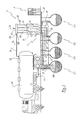
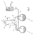
- a service station S comprising four tanks C 1 , C 2 , C 3 and C 4 of a storage facility I, each intended to contain a fuel intended to be distributed from volumetric pumps or "pumps", of which only one, referenced P, is represented.
- the tanks C 1 , C 2 and C 3 are intended to contain light fuels, namely respectively “gasoline 98", “gasoline 95” and "biofuel”.
- the tank 04 is, for its part, intended to contain a heavy fuel, namely diesel, which differs from the light fuels tanks C 1 , C 2 , C 3 by its lower volatility.
- the tank C 1 is being filled from a tank 10 of a delivery truck, as represented by the arrows F 1 .
- a discharge pipe 11 connects the tank 10 to the tank C 1 in which is for example disposed a not shown gauge.
- a vent pipe 12 has its inlet 12a disposed in the upper part of the tank C 1 to collect the vent gas resulting from the filling operation. The circulation of these vent gases is represented by the arrows F 2 .
- the vent duct 12 is provided, in its current part, with a condenser 13 and is connected, at its outlet orifice 12b, to a manifold 14 provided with a safety valve 15 for venting free the manifold in case of overpressure or gas vacuum.
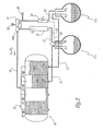
- the outlet 14A of the manifold 14 is connected by a recycling duct 19 to a gas distribution network 16 inside the tank 10 (more particularly visible on the figure 3 ), so that the condenser 13 is integrated in a collection line of the vents of the tank C 1 in the direction of the tank, this line being formed by the meeting of the vent pipe 12, the collector 14, the pipe 19 and of the network 16.
- the vent gases flowing in the pipe 12 are cooled in the condenser 13 and are thus discharged from their fuel particles which condense and flow to the tank C 1 as represented by the arrows F 3 to reach this tank the condensates circulate in a specific evacuation duct 17 shown in phantom, or, alternatively, flow into the vent duct 12, in particular by means of a capillary, either by simple gravity or forced by means a pump not shown.
- the exhaust duct 17 is connected to the discharge pipe 11 so as to promote the flow of condensates by Venturi effect caused by the flow of fuel removed from the tank 10.
- the tanks C 1 , C 3 and C 4 of the installation I are each equipped with a vent duct 22, 32, 42 opening at the outlet into the manifold 14 which is therefore common to all the vent ducts 12, 22, 32 and 42, in the sense that the gases can pass from any duct to another via this manifold.
- the collector 14 is preferably equipped with gas distribution means passing therethrough, sensitive to the gas pressure prevailing in the various vent pipes 12, 22, 32 and 42: if the pressure prevailing in one of these vent pipes is greater than those prevailing in other conduits, these distribution means balance these gas pressures by allowing part of the gases of the over-pressurized duct to pass into the pressurized ducts.
- vent ducts 22 and 32 associated with the tanks C 2 and C 3 of light fuel are each equipped with a condenser 23 and 33 substantially similar to the condenser 13.
- Each condenser 23 and 33 is connected to a duct d discharge of condensates 27 and 37, similar to the conduit 17 associated with the condenser 13 and adapted to direct the condensed vapors at the outlet of each condenser respectively to the tanks C 2 and C 3 .
- the vent duct 42 associated with the diesel fuel tank C 4 is also equipped with a condenser 43.
- This condenser 43 is implanted in a manner analogous to that of the condenser 13 of the duct 12, but differs from this condenser 13 by its dimensioning. More specifically, the cooling capacity of the condenser 43 is significantly lower than that of the condensers 13, 23 and 33.
- the condenser 43 is connected to a condensate discharge duct 47 which, unlike the ducts 17, 27 and 37, does not direct the condensates towards the tank C 4 from which from the vents treated in the condenser, but to one of the tanks of light fuels, namely, for example, the tank C 1 on the figure 1 .
- the vent pipe 42 of the diesel fuel tank C 4 is provided with a valve 20 disposed between the condenser 43 and the manifold 14.
- This valve is preferably tared more weakly than the valve 15, for example at -5mbar instead of -15mbar, so as to allow the introduction of ambient air into the tank C 4 as soon as a depression is formed in that in particular when dispensing fuel from the tank C 4 to the pump P.
- the condensers 13, 23, 33 and 43 are for example adapted to be supplied with a heat transfer fluid from a cooling unit of this fluid, the latter being selected according to environmental standards in force.
- This unit comprises for example one or more compressors able to cool the fluid supplying the condensers at a temperature between -55 ° C and -25 ° C, preferably between about -45 ° C and -40 ° C. Details of embodiment of the condensers of this type are for example given in WO-A-03/006358 .
- the installation I further comprises a suction duct 18 opening, at one of its ends, into the tank C 1 and, at its opposite end, into a gas collection network of the flow meter P.
- the meter is equipped with fuel dispensing guns, respectively provided, for the light fuel dispensing guns, with a suction nozzle for fuel vapors released during the filling of the tank of a motor vehicle. These suction nozzles collect the vent gases resulting from the filling of this tank and send them into the conduit 18 so that these vapors are not released into the atmosphere but returned to the tank C 1 .
- the conduit 18 and the collection network of the meter P thus form means for recovering the gases released during the filling of these tanks, able to meet certain environmental standards.
- a motorist withdraws gasoline 98 from the tank C 1 to fill the tank of his vehicle.
- the dispensing gun delivers the gasoline 98 and sucks at the same time the gaseous phase present in the tank, in particular to limit gaseous escaping harmful to the environment.
- the aspirated gases, represented by the arrows F 4 are, via the suction duct 18, sent to the tank C 1 in practice, the volume of gas sucked is at least 15% greater than the volume of fuel emptied, which causes the increase of the internal gas pressure to this tank.
- diesel fuel distribution generally accounts for more than half of the total fuel distribution for fuel. service station S. Through the manifold 14, a portion of the gas contained in the tank C 1 is then sent, via the vent pipe 42, into the tank C 4 so that the pressure in these tanks tanks is substantially equal.
- a stream of gas charged with light fuel vapors then passes, as indicated by the arrow F 4 , the condenser 43 associated with the tank C 4 , which causes the condensation of at least a portion of these vapors, the condensates being directed, via the conduit 47, to the tank C 1 .
- the remaining cooled gases, essentially free of their light fuel particles, are sent to the tank C 4 .
- the return of the condensates in one of the tanks of light fuel namely in the tank C 1 in the example in the figures
- the concomitant return of cooled gases, removed from most of their fuel particles light, in the tank C 4 and, where appropriate, in the tanks C 1 , C 2 and C 3 make it possible to avoid sending light fuels into the heavy fuel tank C 4 and to cool the internal gas atmosphere tanks, which limits the evaporation of fuels in the tanks.
- the tank 10 is being unloaded so as to refuel substantially simultaneously both the petrol tank 98 C 1 and the diesel tank C 4 , as represented respectively by the arrows F 1 and F 1 ' .
- the discharge duct 11 connects a compartment 10A of the tank 10 to the tank C 1 and a discharge pipe 11 'similar to the pipe 11, connects a compartment 10B of the tank to the tank C 4 , separate compartment 10A.
- the removal of the compartment 10A causes the tank C 1 a gas recovery phenomenon, that is to say an increase in fuel volatility.
- the arrival of the fuel in the tank C 1 flushes the gases initially contained in the tank.
- These two phenomena generate a stream of vent gas from the tank C 1 in the conduit 12.
- These vent gases through the condenser 13 to reach the collector 14, as indicated by the arrow F 2 .
- the condenser 13 causes the condensation of the fuel vapors, the resulting condensates returning, via the conduit 17, into the tank C 1.
- the vent gases discharged from the fuel particles are at a significantly lower temperature. to that they had on entering, between about -40 ° C and -30 ° C.
- the removal of the compartment 10B does not cause a gaseous evaporation phenomenon in the tank C 4 because the gas oil is a non-volatile fuel at room temperature.
- the arrival of the diesel refueling causes the flushing of the gases initially contained in the tank C 4 , these vent gases escaping through the conduit 42 through the condenser 43, as indicated by the arrows F ' 2 .
- the gaseous atmosphere initially contained in the tank C 4 generally comprises a small amount of light fuel vapors, such as gasoline vapors.
- gas from the outside can be introduced into the tank C 1 via the suction duct 18 and gas currents occur in the tank. installation I so that the gas pressure prevailing in each of the 10 tanks C 1 to C 4 is substantially equal through the collector 14, resulting in gas exchange between the tanks.
- the gases expelled from the tank C 4 during its filling are cooled by the condenser 43 and a good portion of the light fuel vapors contained in these gases is condensed, the condensates obtained being discharged to the tank C 1 via the 47.
- the gases removed from the tank C 4 have a lower light fuel vapor content than that vent gases from tanks C 1 to C 3 .
- the cooling capacities of the condenser 43 do not have to be as important as those of the condensers 13, 23 and 33.
- the coolant compressor or coolers circulating in the condenser 43 have a smaller dimensioning compressors associated with each condenser 13, 23, 33.
- a single staged compressor can be used.
- the temperature of the vent gases reaches a level comparable to that of the gases coming from the condensers 13, 23 and 33, that is to say that it is between -40 ° C. and -30 ° C. ° C approx.
- the gases leaving the manifold 14, which are directed towards the tank 10 have a temperature of the order of -30 ° C.
- These gases then feed, via the recycling duct 19, the gas distribution network 16 into the tank 10, so as to replace the volume released by the de-fueled fuel.
- the network 16 distributes the recycled gas feeding it indifferently in the compartments 10A and 10B according to the respective needs of these compartments, related to the flow rate of the fuels discharged
- the gaseous atmosphere in each compartment has a cold temperature, lower than the ambient temperature, thus limiting the revaporization of fuels, especially light, on the surface of liquids being unloaded.
- the continuous inflow of cold recycled gases thus continuously supplies a gaseous mattress of relatively low temperature that stagnates on the surface of the liquid discharged. Any losses related to the revaporizations within the refueling tank 10 are thus greatly limited.
- the installation I according to the invention thus makes it possible to recover, both during the filling of the tanks and their emptying, the vapors of light fuels hitherto lost by the installations of the prior art
- about 95% to 98% of the volatile organic compounds can thus be recondensed in the facility I, minimizing losses of volatile organic compounds for the operator of the service station S and increasing the profitability of this service station.
- the vapors recycled in the tank 10 of the delivery truck consist essentially of very cold air (for example at -25 ° C.) and practically free of volatile organic compounds (less than 5% of volatile compounds), which makes the delivery truck safer and less polluting.
- safety valves 21, which respectively equip the compartments of the tank 10 are solicited only in case of a real malfunction of the network 16, and not to regularly degass these compartments during leu: dump.
- the balancing of the pressures in all the tanks, via the manifold 14, limits both the depressions in the heavy fuel tank C 4 and the overpressures in the tank of light fuels C 1 , C 2 and C 3 , which avoids soliciting the valve 15 and the valve 20, except in the case of a real malfunction of the installation ..
- the overpressures in the tanks of light fuel have anyway tendency to generate significant stresses on the mechanical gauges disposed in these tanks, until lifting or disengaging these gauges. Fuel vapors then infiltrate and stagnate near the part of the gauges accessible from the outside of the tanks, posing risks of explosion when checking the gauges.
- the condenser 43 associated with the diesel tank C 4 operates continuously both during the filling and during the emptying of any of the tanks C 1 to C 4 , so as to minimize the losses of light fuel vapors. .
- the condensers 13, 23 and 33 associated with the tanks C 1 to C 3 are generally intensively stressed only during the respective refilling of these tanks. Outside these filling periods, the cooling intensity developed by these condensers is reduced, while maintaining preferably the heat transfer fluid circulating in these condensers at a temperature below atmospheric temperature to allow these condensers to be at the same temperature. quickly become operational during a discharge and sufficiently effective to treat at least part of the vent gas resulting from the collection of fuel vapor sucked near the dispensing guns of the pump P.
- the condenser 43 is preferably defrosted once a day, during a period of low activity for the service station S, especially at night, while the condensers 13, 23, 33 are preferably de-iced just before and just after filling the tanks C 1 , C 2 and C 3 .
- these defrosts can be achieved by reversing the refrigeration cycle.
- the vent gases from the refueled tank may not be directed permanently to the corresponding condenser, but, on the contrary, be sent successively. to the three condensers 13, 23 and 33.
- the admission of the vent gases in the three condensers is controlled by a set of valves actuated cyclically. In this way, frost is deposited successively in the three condensers, without accumulating exclusively in one of these condensers, thus limiting the overall low condensing performance related to progressive icing condensers.
Landscapes
- Engineering & Computer Science (AREA)
- Mechanical Engineering (AREA)
- Filling Or Discharging Of Gas Storage Vessels (AREA)
- Cooling, Air Intake And Gas Exhaust, And Fuel Tank Arrangements In Propulsion Units (AREA)
- Loading And Unloading Of Fuel Tanks Or Ships (AREA)
Claims (10)
- Kraftstofflagereinrichtung, mindestens einen Leichtöltank (C1, C2, C3) für Kraftstoff mit 98 Oktan, 95 Oktan oder Biokraftstoff und mindestens einen Schweröltank (C4) für Dieselkraftstoff oder Heizöl umfassend, wobei jeder Tank mit einer Be- und Entlüftungsleitung (12, 22, 32, 42), ausgestattet ist, wobei die Be- und Entlüftungsleitung(en) (12, 22, 32) des/der Leichtöltanks (C1, C2, C3) mit Kondensationsmitteln (13, 23, 33) für die in der/den Leitung(en) zirkulierenden Abgase ausgestattet sind, wobei die Kondensate aus diesen Kondensationsmitteln in die oder in mindestens einen der Leichtöltanks abgelassen werden, dadurch gekennzeichnet, dass die Be- und Entlüftungsleitung(en) (42) des/der Schweröltanks (C4) mit Kondensationsmitteln (43) für die in dieser/diesen Leitung(en) zirkulierenden Abgase ausgestattet ist/sind, wobei diese Kondensationsmittel mit Mitteln (47) zum Ablassen von Kondensaten aus diesen Kondensationsmitteln in den oder mindestens in einen der Leichtöltanks (C1, C2, C3) verbunden sind, und dadurch, dass alle Be- und Entlüftungsleitungen (12, 22, 32, 42) des/der Leichtöltanks (C1, C2, C3) und des/der Schweröltank(s) (C4) in denselben Sammelbehälter (14) münden, der diese Be- und Entlüftungsleitungen miteinander verbinden und an einen Tank (10) eines Lieferfahrzeugs anschließbar sein soll.
- Einrichtung nach Anspruch 1, dadurch gekennzeichnet, dass der Sammelbehälter (14) mit Mitteln zum Verteilen der durch ihn hindurchströmenden Gase ausgestattet ist, wobei die Mittel auf den Druck der Gase in den verschiedenen Be- und Entlüftungsleitungen (12, 22, 32, 42) reagierend sind.
- Einrichtung nach einem der Ansprüche 1 oder 2, dadurch gekennzeichnet, dass die Kühlleistung der Kondensationsmittel (43), die dem/den Schweröltank(s) (C4) zugeordnet sind, deutlich geringer ist als die der Kondensationsmittel (13, 23, 33), die dem/den Leichtöltank(s) (C1, C2, C3) zugeordnet sind.
- Einrichtung nach einem der vorhergehenden Ansprüche, dadurch gekennzeichnet, dass die oder jede Be- und Entlüftungsleitung (42) des/der Schweröltank(s) mit einem Ventil (20) ausgestattet ist, das zwischen den Kondensationsmitteln (43), die dieser Leitung zugeordnet sind, und dem Sammelbehälter (14) angeordnet ist und geeignet ist, dem Schweröltank (C4) im Fall von Unterdruck in diesem Tank Umgebungsluft zuzuführen.
- Einrichtung nach Anspruch 4, dadurch gekennzeichnet, dass der Sammelbehälter (14) mit einem Druckentlastungsventil (15) ausgestattet ist, das geeignet ist, den Sammelbehälter im Fall von Über- oder Unterdruck im Sammelbehälter zu be- oder entlüften, und dadurch, dass das Ventil (20), das der oder jeder Be- und Entlüftungsleitung (42) des/der Schweröltank(s) (C4) zugeordnet ist, auf einen geringeren Druck eingestellt ist, als das Druckentlastungsventil (15).
- Einrichtung nach einem der vorhergehenden Ansprüche, dadurch gekennzeichnet, dass sie eine Saugleitung (16) umfasst, die zwischen dem (C1) oder mindestens einem (C1) der Leichtöltank(s) (C1, C2, C3) und Mitteln zum Sammeln des Gases angeschlossen ist, das bei Zuführung von Leichtöl auf Höhe einer Abgabedüse eines Zapfsäulenmessgeräts (P) freiwerdend ist wird.
- Verfahren zum Füllen und/oder Leeren der Tanks einer Kraftstofflagereinrichtung (I), wobei die Einrichtung mindestens einen Leichtöltank (C1, C2, C3) für Kraftstoff mit 98 Oktan, 95 Oktan oder Biokraftstoff und mindestens einen Schweröltank (C4) für Dieselkraftstoff oder Heizöl umfasst, ein Verfahren, bei dem die Abgase von dem/den Leichtöltank(s) gekühlt werden und die aus diesem Kühlvorgang entstehenden Kondensate in den oder in mindestens einen der Leichtöltanks abgelassen werden, dadurch gekennzeichnet, dass die Gase, die in einer oder in Be- und Entlüftungsleitung(en) (42) zirkulieren, welche zwischen Schweröltank(s) (C4) und einem Sammelbehälter (14) angeschlossen ist, der mit den Abgasen des/der Leichtöltank(s) (C1, C2, C3) gespeist wird, ebenfalls gekühlt werden und die aus diesem Kühlvorgang entstehenden Kondensate in den oder in mindestens einen der Leichtöltanks abgelassen werden.
- Verfahren nach Anspruch 7, dadurch gekennzeichnet, dass nach dem Füllen eines beliebigen der Tanks (C1, C2, C3, C4) die Temperatur der Gase aus dem Sammelbehälter (14), die nach außerhalb der Einrichtung abgelassen werden, im Bereich von -30 °C liegt.
- Verfahren nach einem der Ansprüche 7 oder 8, dadurch gekennzeichnet, dass nach dem Füllen und/oder Leeren eines beliebigen der Tanks (C1, C2, C3, C4) die Gase, die in der/den Be- und Entlüftungsleitung(en) (42) des/der Schweröltank(s) (C4) zirkulieren, permanent gekühlt werden.
- Verfahren nach einem der Ansprüche 7 bis 9, dadurch gekennzeichnet, dass nach dem Füllen des oder eines der Leichtöltanks (C1, C2, C3) das Kühlen der von diesem Tank kommenden Gase intensiviert wird.
Applications Claiming Priority (2)
| Application Number | Priority Date | Filing Date | Title |
|---|---|---|---|
| FR0610304A FR2909078B1 (fr) | 2006-11-24 | 2006-11-24 | Installation de stockage de carburants et procede de remplissage et/ou de vidage des cuves de cette installation |
| PCT/FR2007/001918 WO2008071865A1 (fr) | 2006-11-24 | 2007-11-21 | Installation de stockage de carburants et procede de remplissage et/ou de vidage des cuves de cette installation |
Publications (2)
| Publication Number | Publication Date |
|---|---|
| EP2094601A1 EP2094601A1 (de) | 2009-09-02 |
| EP2094601B1 true EP2094601B1 (de) | 2012-01-11 |
Family
ID=38179979
Family Applications (1)
| Application Number | Title | Priority Date | Filing Date |
|---|---|---|---|
| EP07870322A Not-in-force EP2094601B1 (de) | 2006-11-24 | 2007-11-21 | Einrichtung für brennstofflagerung und verfahren zum befüllen/leeren der tanks dieser einrichtung |
Country Status (11)
| Country | Link |
|---|---|
| US (1) | US8256471B2 (de) |
| EP (1) | EP2094601B1 (de) |
| KR (1) | KR20090088919A (de) |
| CN (1) | CN101563288B (de) |
| AT (1) | ATE540896T1 (de) |
| AU (1) | AU2007331349B2 (de) |
| BR (1) | BRPI0719434A2 (de) |
| CA (1) | CA2669288A1 (de) |
| FR (1) | FR2909078B1 (de) |
| WO (1) | WO2008071865A1 (de) |
| ZA (1) | ZA200903269B (de) |
Families Citing this family (15)
| Publication number | Priority date | Publication date | Assignee | Title |
|---|---|---|---|---|
| GB0714399D0 (en) * | 2007-07-24 | 2007-09-05 | Vapasava Vr Ltd | System and method of petrol vapour recovery |
| US9080117B2 (en) * | 2008-01-22 | 2015-07-14 | GER Enterprises, LLC | Biofuel production method and system |
| CN101637663B (zh) * | 2008-08-02 | 2011-10-12 | 中国石油化工股份有限公司 | 储罐区排放气治理方法 |
| FR2947538B1 (fr) | 2009-07-03 | 2011-06-17 | Inst Francais Du Petrole | Installation et procede de stockage de carburant |
| CN102756714A (zh) * | 2011-04-26 | 2012-10-31 | 北京福吉长安防爆材料盐城有限责任公司 | 多油品汽油汽车加油设备 |
| FR2999553B1 (fr) * | 2012-12-18 | 2015-11-13 | IFP Energies Nouvelles | Installation de stockage et de distribution de carburants, notamment pour vehicules automobiles |
| US10767859B2 (en) * | 2014-08-19 | 2020-09-08 | Adler Hot Oil Service, LLC | Wellhead gas heater |
| FR3051182B1 (fr) * | 2016-05-10 | 2018-05-18 | Tokheim Holding B.V. | Installation de stockage et de distribution de carburant |
| SE540241C2 (en) * | 2016-09-09 | 2018-05-08 | Scania Cv Ab | An arrangement for mounting a gas pipe to a vehicle |
| SE543451C2 (en) * | 2018-02-19 | 2021-02-23 | Wayne Fueling Systems Sweden Ab | Fuel dispensing unit and method for handling a fuel dispensing unit |
| CN113226949B (zh) | 2018-11-14 | 2023-06-02 | 富兰克林加油系统公司 | 压力真空阀 |
| CN111071980B (zh) * | 2019-12-27 | 2024-10-01 | 赫普能源环境科技股份有限公司 | 一种液体电燃料加注回收罐车及电力储存运输方法 |
| CN113390018B (zh) * | 2020-03-13 | 2022-06-07 | 中国石油化工股份有限公司 | 一种液化烃罐的气相系统 |
| CN113291446B (zh) * | 2021-06-29 | 2022-04-19 | 广船国际有限公司 | 一种甲醇双燃料船舶日用柜的补给系统及其使用方法 |
| CN116216624B (zh) * | 2022-12-29 | 2025-11-21 | 广州发展碧辟油品有限公司 | 一种油气回收调节方法 |
Family Cites Families (12)
| Publication number | Priority date | Publication date | Assignee | Title |
|---|---|---|---|---|
| US4320788A (en) * | 1975-06-23 | 1982-03-23 | Union Oil Company Of California | Apparatus for the bulk delivery of volatile liquids |
| US4058148A (en) * | 1976-03-18 | 1977-11-15 | Exxon Research & Engineering Co. | Vapor hose hookup assurance |
| US4457349A (en) * | 1982-01-19 | 1984-07-03 | Chevron Research Company | Volatile hydrocarbon recovery system for tank truck unloading headers |
| US5289857A (en) * | 1991-11-27 | 1994-03-01 | Pyles Charles E | Vapor recovery system |
| EP0598928B1 (de) * | 1992-11-17 | 1995-03-15 | Scheidt & Bachmann Gmbh | Kraftfahrzeugtankstelle mit Rückgewinnung von Brennstoffdampf |
| US5472012A (en) * | 1994-01-14 | 1995-12-05 | Dover Corporation | Storage tank shutoff valve |
| US5850849A (en) * | 1994-01-14 | 1998-12-22 | Dover Corporation | Storage tank shutoff valve with double cam assembly |
| FR2757146B1 (fr) * | 1996-12-17 | 1999-01-08 | Schlumberger Ind Sa | Dispositif collecteur d'une pluralite de tuyaux d'evacuation de vapeurs |
| US6382240B1 (en) * | 2000-06-15 | 2002-05-07 | Macdonald William David | Apparatus for fuel tanker oveflow diversion and vapor separation |
| FR2827268B1 (fr) * | 2001-07-12 | 2004-03-26 | Sellco Sa | Installation de stockage de carburant dans une station-service et procede de remplissage d'une cuve de station-service |
| FR2855869B1 (fr) * | 2003-06-06 | 2008-01-04 | Gaz Transport & Technigaz | Procede de refroidissement d'un produit, notamment pour la liquefaction d'un gaz, et dispositif pour sa mise en oeuvre |
| US7270155B2 (en) * | 2005-07-27 | 2007-09-18 | Wei Pin Ho | Gasoline vapor recycling system for gasoline tank |
-
2006
- 2006-11-24 FR FR0610304A patent/FR2909078B1/fr not_active Expired - Fee Related
-
2007
- 2007-11-21 US US12/516,022 patent/US8256471B2/en not_active Expired - Fee Related
- 2007-11-21 EP EP07870322A patent/EP2094601B1/de not_active Not-in-force
- 2007-11-21 KR KR1020097013160A patent/KR20090088919A/ko not_active Ceased
- 2007-11-21 BR BRPI0719434-0A patent/BRPI0719434A2/pt not_active IP Right Cessation
- 2007-11-21 CA CA002669288A patent/CA2669288A1/fr not_active Abandoned
- 2007-11-21 AT AT07870322T patent/ATE540896T1/de active
- 2007-11-21 CN CN200780043649XA patent/CN101563288B/zh not_active Expired - Fee Related
- 2007-11-21 WO PCT/FR2007/001918 patent/WO2008071865A1/fr not_active Ceased
- 2007-11-21 AU AU2007331349A patent/AU2007331349B2/en not_active Ceased
-
2009
- 2009-05-12 ZA ZA200903269A patent/ZA200903269B/xx unknown
Also Published As
| Publication number | Publication date |
|---|---|
| CN101563288A (zh) | 2009-10-21 |
| CA2669288A1 (fr) | 2008-06-19 |
| AU2007331349A1 (en) | 2008-06-19 |
| CN101563288B (zh) | 2013-03-27 |
| EP2094601A1 (de) | 2009-09-02 |
| WO2008071865A1 (fr) | 2008-06-19 |
| ZA200903269B (en) | 2010-03-31 |
| FR2909078B1 (fr) | 2009-01-09 |
| AU2007331349B2 (en) | 2012-02-02 |
| ATE540896T1 (de) | 2012-01-15 |
| KR20090088919A (ko) | 2009-08-20 |
| FR2909078A1 (fr) | 2008-05-30 |
| BRPI0719434A2 (pt) | 2013-12-03 |
| US20100051134A1 (en) | 2010-03-04 |
| US8256471B2 (en) | 2012-09-04 |
Similar Documents
| Publication | Publication Date | Title |
|---|---|---|
| EP2094601B1 (de) | Einrichtung für brennstofflagerung und verfahren zum befüllen/leeren der tanks dieser einrichtung | |
| EP3650741B1 (de) | Verfahren und vorrichtung zur lagerung und versorgung mit verflüssigtem wasserstoff | |
| US5213142A (en) | Stage II vapor recovery system | |
| US5327943A (en) | Multi-purpose nozzle with liquid pickup | |
| EP4153900B1 (de) | Vorrichtung und verfahren zur übertragung einer kryogenen flüssigkeit | |
| FR3051182A1 (fr) | Installation de stockage et de distribution de carburant | |
| US5234036A (en) | Dispensing fuel with aspiration of condensed vapors | |
| EP2117992B1 (de) | Anlage und verfahren zur lagerung von brennstoffen auf alkoholbasis | |
| FR2829745A1 (fr) | Procede et dispositif de lutte contre l'incendie | |
| WO2003006358A1 (fr) | Installation de stockage de carburant dans une station-service et procede de remplissage d'une cuve de station-service | |
| US5199471A (en) | Process to prevent vapor blockage for stage II vapor recovery | |
| WO2014096596A1 (fr) | Installation de stockage et de distribution de carburants, notamment pour véhicules automobiles | |
| EP3488139A1 (de) | Modul und system zur druckentlastung eines kryogenen tanks | |
| EP3904664B1 (de) | Siphon für agr-kondensate | |
| EP2448860B1 (de) | Anlage und verfahren zur kraftstofflagerung | |
| US20250083088A1 (en) | Methods of butane delivery | |
| EP2948665B1 (de) | Kältekreislauf-konditionierungssystem | |
| RU94549U1 (ru) | Система для улавливания и рекуперации паров горючего из резервуаров | |
| EP2075219A1 (de) | Zapfpistole für Kraftstoff | |
| US20210285451A1 (en) | Liquid Hydrocarbon Transfer System And Assembly | |
| EP4399438A1 (de) | Verfahren und vorrichtung zur übertragung einer kryogenen flüssigkeit | |
| FR2877854A1 (fr) | Dispositif de separation d'eau et de condensats de composes organiques volatils | |
| FR3082150A1 (fr) | Reservoir avec canalisation empechant un passage de carburant liquide vers un dispositif de stockage des vapeurs de carburant | |
| FR2738191A1 (fr) | Reservoir de carburant perfectionne pour vehicule automobile |
Legal Events
| Date | Code | Title | Description |
|---|---|---|---|
| PUAI | Public reference made under article 153(3) epc to a published international application that has entered the european phase |
Free format text: ORIGINAL CODE: 0009012 |
|
| 17P | Request for examination filed |
Effective date: 20090624 |
|
| AK | Designated contracting states |
Kind code of ref document: A1 Designated state(s): AT BE BG CH CY CZ DE DK EE ES FI FR GB GR HU IE IS IT LI LT LU LV MC MT NL PL PT RO SE SI SK TR |
|
| DAX | Request for extension of the european patent (deleted) | ||
| RAP1 | Party data changed (applicant data changed or rights of an application transferred) |
Owner name: SELLES, SERGE ALBERT PIERRE Owner name: IFP ENERGIES NOUVELLES |
|
| REG | Reference to a national code |
Ref country code: DE Ref legal event code: R079 Ref document number: 602007020080 Country of ref document: DE Free format text: PREVIOUS MAIN CLASS: B67D0005040000 Ipc: B67D0007040000 |
|
| GRAP | Despatch of communication of intention to grant a patent |
Free format text: ORIGINAL CODE: EPIDOSNIGR1 |
|
| RIC1 | Information provided on ipc code assigned before grant |
Ipc: B67D 7/04 20100101AFI20110705BHEP |
|
| GRAS | Grant fee paid |
Free format text: ORIGINAL CODE: EPIDOSNIGR3 |
|
| GRAA | (expected) grant |
Free format text: ORIGINAL CODE: 0009210 |
|
| AK | Designated contracting states |
Kind code of ref document: B1 Designated state(s): AT BE BG CH CY CZ DE DK EE ES FI FR GB GR HU IE IS IT LI LT LU LV MC MT NL PL PT RO SE SI SK TR |
|
| REG | Reference to a national code |
Ref country code: GB Ref legal event code: FG4D Free format text: NOT ENGLISH |
|
| REG | Reference to a national code |
Ref country code: CH Ref legal event code: EP |
|
| REG | Reference to a national code |
Ref country code: AT Ref legal event code: REF Ref document number: 540896 Country of ref document: AT Kind code of ref document: T Effective date: 20120115 |
|
| REG | Reference to a national code |
Ref country code: IE Ref legal event code: FG4D |
|
| REG | Reference to a national code |
Ref country code: DE Ref legal event code: R096 Ref document number: 602007020080 Country of ref document: DE Effective date: 20120315 |
|
| REG | Reference to a national code |
Ref country code: NL Ref legal event code: VDEP Effective date: 20120111 |
|
| PG25 | Lapsed in a contracting state [announced via postgrant information from national office to epo] |
Ref country code: SI Free format text: LAPSE BECAUSE OF FAILURE TO SUBMIT A TRANSLATION OF THE DESCRIPTION OR TO PAY THE FEE WITHIN THE PRESCRIBED TIME-LIMIT Effective date: 20120111 |
|
| LTIE | Lt: invalidation of european patent or patent extension |
Effective date: 20120111 |
|
| PG25 | Lapsed in a contracting state [announced via postgrant information from national office to epo] |
Ref country code: BG Free format text: LAPSE BECAUSE OF FAILURE TO SUBMIT A TRANSLATION OF THE DESCRIPTION OR TO PAY THE FEE WITHIN THE PRESCRIBED TIME-LIMIT Effective date: 20120411 Ref country code: NL Free format text: LAPSE BECAUSE OF FAILURE TO SUBMIT A TRANSLATION OF THE DESCRIPTION OR TO PAY THE FEE WITHIN THE PRESCRIBED TIME-LIMIT Effective date: 20120111 Ref country code: LT Free format text: LAPSE BECAUSE OF FAILURE TO SUBMIT A TRANSLATION OF THE DESCRIPTION OR TO PAY THE FEE WITHIN THE PRESCRIBED TIME-LIMIT Effective date: 20120111 Ref country code: IS Free format text: LAPSE BECAUSE OF FAILURE TO SUBMIT A TRANSLATION OF THE DESCRIPTION OR TO PAY THE FEE WITHIN THE PRESCRIBED TIME-LIMIT Effective date: 20120511 |
|
| REG | Reference to a national code |
Ref country code: IE Ref legal event code: FD4D |
|
| PG25 | Lapsed in a contracting state [announced via postgrant information from national office to epo] |
Ref country code: LV Free format text: LAPSE BECAUSE OF FAILURE TO SUBMIT A TRANSLATION OF THE DESCRIPTION OR TO PAY THE FEE WITHIN THE PRESCRIBED TIME-LIMIT Effective date: 20120111 Ref country code: GR Free format text: LAPSE BECAUSE OF FAILURE TO SUBMIT A TRANSLATION OF THE DESCRIPTION OR TO PAY THE FEE WITHIN THE PRESCRIBED TIME-LIMIT Effective date: 20120412 Ref country code: PT Free format text: LAPSE BECAUSE OF FAILURE TO SUBMIT A TRANSLATION OF THE DESCRIPTION OR TO PAY THE FEE WITHIN THE PRESCRIBED TIME-LIMIT Effective date: 20120511 Ref country code: FI Free format text: LAPSE BECAUSE OF FAILURE TO SUBMIT A TRANSLATION OF THE DESCRIPTION OR TO PAY THE FEE WITHIN THE PRESCRIBED TIME-LIMIT Effective date: 20120111 Ref country code: PL Free format text: LAPSE BECAUSE OF FAILURE TO SUBMIT A TRANSLATION OF THE DESCRIPTION OR TO PAY THE FEE WITHIN THE PRESCRIBED TIME-LIMIT Effective date: 20120111 |
|
| REG | Reference to a national code |
Ref country code: AT Ref legal event code: MK05 Ref document number: 540896 Country of ref document: AT Kind code of ref document: T Effective date: 20120111 |
|
| PG25 | Lapsed in a contracting state [announced via postgrant information from national office to epo] |
Ref country code: CY Free format text: LAPSE BECAUSE OF FAILURE TO SUBMIT A TRANSLATION OF THE DESCRIPTION OR TO PAY THE FEE WITHIN THE PRESCRIBED TIME-LIMIT Effective date: 20120111 |
|
| PG25 | Lapsed in a contracting state [announced via postgrant information from national office to epo] |
Ref country code: SE Free format text: LAPSE BECAUSE OF FAILURE TO SUBMIT A TRANSLATION OF THE DESCRIPTION OR TO PAY THE FEE WITHIN THE PRESCRIBED TIME-LIMIT Effective date: 20120111 Ref country code: RO Free format text: LAPSE BECAUSE OF FAILURE TO SUBMIT A TRANSLATION OF THE DESCRIPTION OR TO PAY THE FEE WITHIN THE PRESCRIBED TIME-LIMIT Effective date: 20120111 Ref country code: DK Free format text: LAPSE BECAUSE OF FAILURE TO SUBMIT A TRANSLATION OF THE DESCRIPTION OR TO PAY THE FEE WITHIN THE PRESCRIBED TIME-LIMIT Effective date: 20120111 Ref country code: EE Free format text: LAPSE BECAUSE OF FAILURE TO SUBMIT A TRANSLATION OF THE DESCRIPTION OR TO PAY THE FEE WITHIN THE PRESCRIBED TIME-LIMIT Effective date: 20120111 Ref country code: IE Free format text: LAPSE BECAUSE OF FAILURE TO SUBMIT A TRANSLATION OF THE DESCRIPTION OR TO PAY THE FEE WITHIN THE PRESCRIBED TIME-LIMIT Effective date: 20120111 Ref country code: CZ Free format text: LAPSE BECAUSE OF FAILURE TO SUBMIT A TRANSLATION OF THE DESCRIPTION OR TO PAY THE FEE WITHIN THE PRESCRIBED TIME-LIMIT Effective date: 20120111 |
|
| PLBE | No opposition filed within time limit |
Free format text: ORIGINAL CODE: 0009261 |
|
| STAA | Information on the status of an ep patent application or granted ep patent |
Free format text: STATUS: NO OPPOSITION FILED WITHIN TIME LIMIT |
|
| PG25 | Lapsed in a contracting state [announced via postgrant information from national office to epo] |
Ref country code: SK Free format text: LAPSE BECAUSE OF FAILURE TO SUBMIT A TRANSLATION OF THE DESCRIPTION OR TO PAY THE FEE WITHIN THE PRESCRIBED TIME-LIMIT Effective date: 20120111 Ref country code: IT Free format text: LAPSE BECAUSE OF FAILURE TO SUBMIT A TRANSLATION OF THE DESCRIPTION OR TO PAY THE FEE WITHIN THE PRESCRIBED TIME-LIMIT Effective date: 20120111 |
|
| 26N | No opposition filed |
Effective date: 20121012 |
|
| PG25 | Lapsed in a contracting state [announced via postgrant information from national office to epo] |
Ref country code: AT Free format text: LAPSE BECAUSE OF FAILURE TO SUBMIT A TRANSLATION OF THE DESCRIPTION OR TO PAY THE FEE WITHIN THE PRESCRIBED TIME-LIMIT Effective date: 20120111 |
|
| REG | Reference to a national code |
Ref country code: DE Ref legal event code: R097 Ref document number: 602007020080 Country of ref document: DE Effective date: 20121012 |
|
| PG25 | Lapsed in a contracting state [announced via postgrant information from national office to epo] |
Ref country code: ES Free format text: LAPSE BECAUSE OF FAILURE TO SUBMIT A TRANSLATION OF THE DESCRIPTION OR TO PAY THE FEE WITHIN THE PRESCRIBED TIME-LIMIT Effective date: 20120422 |
|
| BERE | Be: lapsed |
Owner name: IFP ENERGIES NOUVELLES Effective date: 20121130 Owner name: SELLES, SERGE ALBERT PIERRE Effective date: 20121130 |
|
| REG | Reference to a national code |
Ref country code: CH Ref legal event code: PL |
|
| PG25 | Lapsed in a contracting state [announced via postgrant information from national office to epo] |
Ref country code: LI Free format text: LAPSE BECAUSE OF NON-PAYMENT OF DUE FEES Effective date: 20121130 Ref country code: CH Free format text: LAPSE BECAUSE OF NON-PAYMENT OF DUE FEES Effective date: 20121130 |
|
| PG25 | Lapsed in a contracting state [announced via postgrant information from national office to epo] |
Ref country code: BE Free format text: LAPSE BECAUSE OF NON-PAYMENT OF DUE FEES Effective date: 20121130 |
|
| PG25 | Lapsed in a contracting state [announced via postgrant information from national office to epo] |
Ref country code: MT Free format text: LAPSE BECAUSE OF FAILURE TO SUBMIT A TRANSLATION OF THE DESCRIPTION OR TO PAY THE FEE WITHIN THE PRESCRIBED TIME-LIMIT Effective date: 20120111 |
|
| PGFP | Annual fee paid to national office [announced via postgrant information from national office to epo] |
Ref country code: GB Payment date: 20131120 Year of fee payment: 7 Ref country code: DE Payment date: 20131122 Year of fee payment: 7 Ref country code: FR Payment date: 20131002 Year of fee payment: 7 |
|
| PG25 | Lapsed in a contracting state [announced via postgrant information from national office to epo] |
Ref country code: TR Free format text: LAPSE BECAUSE OF FAILURE TO SUBMIT A TRANSLATION OF THE DESCRIPTION OR TO PAY THE FEE WITHIN THE PRESCRIBED TIME-LIMIT Effective date: 20120111 Ref country code: MC Free format text: LAPSE BECAUSE OF NON-PAYMENT OF DUE FEES Effective date: 20121130 |
|
| PG25 | Lapsed in a contracting state [announced via postgrant information from national office to epo] |
Ref country code: LU Free format text: LAPSE BECAUSE OF NON-PAYMENT OF DUE FEES Effective date: 20121121 |
|
| PG25 | Lapsed in a contracting state [announced via postgrant information from national office to epo] |
Ref country code: HU Free format text: LAPSE BECAUSE OF FAILURE TO SUBMIT A TRANSLATION OF THE DESCRIPTION OR TO PAY THE FEE WITHIN THE PRESCRIBED TIME-LIMIT Effective date: 20071121 |
|
| REG | Reference to a national code |
Ref country code: DE Ref legal event code: R119 Ref document number: 602007020080 Country of ref document: DE |
|
| GBPC | Gb: european patent ceased through non-payment of renewal fee |
Effective date: 20141121 |
|
| REG | Reference to a national code |
Ref country code: FR Ref legal event code: ST Effective date: 20150731 |
|
| PG25 | Lapsed in a contracting state [announced via postgrant information from national office to epo] |
Ref country code: GB Free format text: LAPSE BECAUSE OF NON-PAYMENT OF DUE FEES Effective date: 20141121 Ref country code: DE Free format text: LAPSE BECAUSE OF NON-PAYMENT OF DUE FEES Effective date: 20150602 |
|
| PG25 | Lapsed in a contracting state [announced via postgrant information from national office to epo] |
Ref country code: FR Free format text: LAPSE BECAUSE OF NON-PAYMENT OF DUE FEES Effective date: 20141201 |