EP2096307A2 - Compresseur de type plaque inclinée - Google Patents
Compresseur de type plaque inclinée Download PDFInfo
- Publication number
- EP2096307A2 EP2096307A2 EP09002156A EP09002156A EP2096307A2 EP 2096307 A2 EP2096307 A2 EP 2096307A2 EP 09002156 A EP09002156 A EP 09002156A EP 09002156 A EP09002156 A EP 09002156A EP 2096307 A2 EP2096307 A2 EP 2096307A2
- Authority
- EP
- European Patent Office
- Prior art keywords
- sleeve
- tilting plate
- stopper
- flanges
- type compressor
- Prior art date
- Legal status (The legal status is an assumption and is not a legal conclusion. Google has not performed a legal analysis and makes no representation as to the accuracy of the status listed.)
- Withdrawn
Links
- 230000006835 compression Effects 0.000 claims abstract description 8
- 238000007906 compression Methods 0.000 claims abstract description 8
- 239000003507 refrigerant Substances 0.000 claims description 16
- 239000003921 oil Substances 0.000 description 6
- 238000006073 displacement reaction Methods 0.000 description 5
- 239000010687 lubricating oil Substances 0.000 description 4
- 239000003595 mist Substances 0.000 description 4
- 238000004378 air conditioning Methods 0.000 description 2
- 230000004323 axial length Effects 0.000 description 2
- 238000007599 discharging Methods 0.000 description 2
- 238000004519 manufacturing process Methods 0.000 description 2
- 238000000034 method Methods 0.000 description 1
- 230000004048 modification Effects 0.000 description 1
- 238000012986 modification Methods 0.000 description 1
Images


Classifications
-
- F—MECHANICAL ENGINEERING; LIGHTING; HEATING; WEAPONS; BLASTING
- F04—POSITIVE - DISPLACEMENT MACHINES FOR LIQUIDS; PUMPS FOR LIQUIDS OR ELASTIC FLUIDS
- F04B—POSITIVE-DISPLACEMENT MACHINES FOR LIQUIDS; PUMPS
- F04B27/00—Multi-cylinder pumps specially adapted for elastic fluids and characterised by number or arrangement of cylinders
- F04B27/08—Multi-cylinder pumps specially adapted for elastic fluids and characterised by number or arrangement of cylinders having cylinders coaxial with, or parallel or inclined to, main shaft axis
-
- F—MECHANICAL ENGINEERING; LIGHTING; HEATING; WEAPONS; BLASTING
- F04—POSITIVE - DISPLACEMENT MACHINES FOR LIQUIDS; PUMPS FOR LIQUIDS OR ELASTIC FLUIDS
- F04B—POSITIVE-DISPLACEMENT MACHINES FOR LIQUIDS; PUMPS
- F04B27/00—Multi-cylinder pumps specially adapted for elastic fluids and characterised by number or arrangement of cylinders
- F04B27/08—Multi-cylinder pumps specially adapted for elastic fluids and characterised by number or arrangement of cylinders having cylinders coaxial with, or parallel or inclined to, main shaft axis
- F04B27/10—Multi-cylinder pumps specially adapted for elastic fluids and characterised by number or arrangement of cylinders having cylinders coaxial with, or parallel or inclined to, main shaft axis having stationary cylinders
- F04B27/1036—Component parts, details, e.g. sealings, lubrication
- F04B27/1054—Actuating elements
- F04B27/1072—Pivot mechanisms
-
- F—MECHANICAL ENGINEERING; LIGHTING; HEATING; WEAPONS; BLASTING
- F04—POSITIVE - DISPLACEMENT MACHINES FOR LIQUIDS; PUMPS FOR LIQUIDS OR ELASTIC FLUIDS
- F04B—POSITIVE-DISPLACEMENT MACHINES FOR LIQUIDS; PUMPS
- F04B25/00—Multi-stage pumps
- F04B25/04—Multi-stage pumps having cylinders coaxial with, or parallel or inclined to, main shaft axis
-
- F—MECHANICAL ENGINEERING; LIGHTING; HEATING; WEAPONS; BLASTING
- F04—POSITIVE - DISPLACEMENT MACHINES FOR LIQUIDS; PUMPS FOR LIQUIDS OR ELASTIC FLUIDS
- F04B—POSITIVE-DISPLACEMENT MACHINES FOR LIQUIDS; PUMPS
- F04B27/00—Multi-cylinder pumps specially adapted for elastic fluids and characterised by number or arrangement of cylinders
- F04B27/08—Multi-cylinder pumps specially adapted for elastic fluids and characterised by number or arrangement of cylinders having cylinders coaxial with, or parallel or inclined to, main shaft axis
- F04B27/10—Multi-cylinder pumps specially adapted for elastic fluids and characterised by number or arrangement of cylinders having cylinders coaxial with, or parallel or inclined to, main shaft axis having stationary cylinders
- F04B27/1036—Component parts, details, e.g. sealings, lubrication
Definitions
- the present invention relates to a tilting plate type compressor.
- a tilting plate type compressor In a tilting plate type compressor, its discharge amount is controlled by changing a tilted angle of a tilting plate (swash plate, wobble plate) from a minimum angle to a maximum angle.
- the minimum angle is set by fixing a position of a sleeve that can be moved along a drive shaft together with the tilting plate. Fixing the position of the sleeve is done by making the sleeve contacted with a stopper.
- Patent Document 1 discloses a "variable capacity swash plate-type compressor".
- Patent Document 2 discloses a "swash plate type variable capacity compressor”.
- Patent Document 3 discloses an "oscillating swash plate type compressor”.
- variable capacity swash plate-type compressor of the Patent Document 1 a position of a sleeve 151 is fixed when a coil spring 153 pushing the sleeve 151 is most compressed as shown in Fig. 10 .
- a position of a sleeve is fixed when the sleeve is made contacted with a stop ring being fixed on a drive shaft.
- a position of a sleeve is fixed when the sleeve is made contacted with a washer.
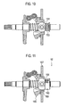
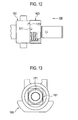
- Figs 11 to 13 shows a configuration in which fixing of a sleeve 161 is done by making the sleeve 161 contacted with a stopper 163 as disclosed in the Patent Documents 2 and 3.
- a journal 165 is swingably connected to the sleeve 161.
- a tilting plate 167 is fixed on (screwed together with) a hub 169 of the journal 165. Pistons are coupled with an outer circumferential edge of the tilting plate 167 via shoes.
- the journal 165 needs to be larger, too. If the journal 165 is not made large, thickness of the hub 169 becomes thin. As a result, strength at the fixing portion by screwing between the tilting plate 167 and the hub 169 becomes weak. On the other hand, the journal 165 needs to be large in order to ensure sufficient thickness (strength) for the hub 169. In this case, the discharge amount (piston stroke) may become too large because the pistons need to be positioned more outward in a radial direction. In addition, the tilting plate type compressor must become large (have larger outer diameter) itself.
- an end face 171 of the sleeve 161 and an end face 173 of the stopper 163 are contacted each other.
- Contacting noise should occur on the contacting end faces 171 and 173 because each of the end face 171 and 173 has a wide ring-like plane surface (see Fig. 12 ).
- the end faces 171 and 173 may be adhered each other due to oil and thereby resistance becomes large when increasing the discharge amount.
- An aspect of the present invention is to provide a tilting plate type compressor that includes a tilting plate capable of rotating together with a rotation of a drive shaft and capable of adjusting a tilted angle thereof to the drive shaft, a compression mechanism including pistons and cylinders for suctioning and compressing refrigerant while the pistons are reciprocated due to tilting rotation of the tilting plate to discharge the refrigerant from the cylinders, a sleeve capable of adjusting the tilted angle of the tilting plate by sliding along the drive shaft, and a stopper for fixing the sleeve at a position for setting the tilted angle of the tilting plate to a minimum angle.
- flanges are provided on the sleeve to be contacted with the stopper for fixing the sleeve at the position.
- a diameter of the sleeve can be made smaller than that of a conventional one and thereby downsizing can be achieved because the position of the sleeve is fixed by contacting the flanges with the stopper. Therefore, growing large of the tilting plate type compressor can be prevented and excessive discharging due to positioning fluctuation of the pistons can be prevented.
- contacting noise can be made smaller than that in a conventional one and adhesion of the sleeve and the stopper can be reduced because the flanges of the sleeve are contacted with the stopper. Further, resistance when increasing the discharge amount can also be prevented.
- a recess is formed on the stopper for accommodating an end of the sleeve while the flanges are contacting with the stopper.
- the tilting plate type compressor can shorten its axial length and thereby can be downsized because the end of the sleeve is made entered into the recess of the stopper.
- the flanges are formed only with portions to be contacted with the stopper.
- each of the flanges is provided on the sleeve in a pair with being projected in opposite directions perpendicular to the drive shaft.
- each of the flanges has a ring shape, a pair of pins is inserted within the pair of the flanges, respectively, and a journal on which the tilting plate is fixed is coupled with the sleeve swingably via the pair of pins.
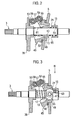
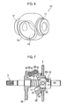
- a tilting plate type compressor 1 according to an embodiment of the present invention will be explained with reference to Figs. 1 to 8 .
- the tilting plate type compressor 1 includes a tilting plate 5, a compression mechanism 11, a sleeve 13 and a stopper 15.
- a tilted angle of the tilting plate 5 to a drive shaft 3 can be adjusted.
- the tilted angle of the tilting plate 5 is varied according to sliding of the sleeve 13 along the drive shaft 3.
- the compression mechanism 11 includes pistons 7 and cylinders 9. Refrigerant is suctioned, compressed and then discharged from the cylinders 9 while the pistons 7 are reciprocated by swinging rotation of the tilting plate 5.
- the stopper 15 fixes a position of the sleeve 13 in an axial direction so as to set the tilted angle of the tilting plate 5 to the minimum angle.
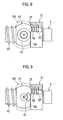
- the sleeve 13 has a pair of circular flanges 17 (see Figs. 3 and 6 ). The position of the sleeve 13 is fixed when the flanges 17 are contacted with the stopper 15. A recess 21 is formed on the stopper 15 (see Figs. 2 and 3 ). An end 19 (see Figs. 4 to 6 ) of the sleeve 13 enters into an inside of the recess 21 when the flanges 17 contact with the stopper 15 (see Figs. 3 and 4 ).
- the compressor is applied to a refrigerant system in an air conditioning unit for a vehicle.
- High temperature and high pressure refrigerant adiabatically compressed by the compressor 1 is liquefied by a condenser and then adiabatically expanded by an expansion valve. Subsequently, the refrigerant is evaporated with being heated by an evaporator to generate cooled air and then returned to the compressor 1 to be adiabatically compressed again. Note that a proper amount of lubricating oil is included in the refrigerant gas.
- the compressor 1 includes a front housing 23, a cylinder block 25, a valve plate 27 and a rear housing 29. These components are integrated by through-bolts 30.
- An input pulley is supported on the front housing 23 via a bearing. Output rotation of an engine is input to the input pulley.
- An electromagnetic clutch is installed between the input pulley and the drive shaft 3. The electromagnetic clutch is disengaged to separate the compressor 1 and the engine when the air conditioning unit is turned off.
- a crank chamber 31 is provided between the front housing 23 and the cylinder block 25. The lubricating oil is filled in the crank chamber 31.
- the cylinders 9 are provided within the cylinder block 25 along a circumferential direction at even intervals. In the compression mechanism 11, the pistons 7 reciprocate within the cylinders 9, respectively.
- the drive shaft 3 is supported by the front housing 23 and the rear housing 25 via needle bearings 33 and 35 at its both front and rear ends.
- a thrust bearing 37 provided between the stopper 15 and the rear housing 25 receives a backward thrust force applied to the drive shaft 3.
- a rug plate 39 is spline-coupled with the drive shaft 3.
- Another thrust bearing 41 provided between the lug plate 39 and the front housing 23 receives a forward thrust force applied to the drive shaft 3.
- a through hole 43 is formed on the sleeve 13 (see Figs. 1 , 2 and 6 ).
- the drive shaft 3 is inserted into the through hole 43 and thereby the sleeve 13 is coupled with the drive shaft 3 slidably along the drive shaft 3.
- a journal 45 is coupled with the sleeve 13 via a pair of pins 47 to be able to swing.
- the pair of flanges 17 on the sleeve 13 supports the pair of pins 47.
- the tilting plate 5 is fixed on an outer circumference of a hub 49 provided on the journal 45 by screwing with its position being set by a washer 50.
- Each of the pistons 7 is coupled with the tilting plate 5 via a pair of half-sphere shaped shoes 51.
- a pair of arms 53 provided on the lug plate 39 and another pair of arms 55 (also see Fig. 5 : the drive shaft 3, the tilting plate 5, the stopper 15 and the return spring 63 are not shown in Fig. 5 ) provided on the journal 45 are coupled with each other via a linkage 57 and pins 59.
- the linkage 57 can swing around each of the pins 59.
- a rotating torque from the engine is input into the input pulley to rotate the drive shaft 3 (the lug plate 39). This rotation is transmitted to the journal 45 (the tilting plate 5) via the linkage 57 and the pins 59.
- the tilting plate 5 drives the compression mechanism 11 by reciprocating each of the pistons 7 with a stroke displacement according to its tilted angle.
- the compression mechanism 11 suctions, compresses and then discharges the refrigerant by an amount according to the stroke displacement.
- the sleeve 13 is supported in the axial direction by a destroke spring 61, a return spring 63 and a differential pressure (Pd - Ps) between a discharge pressure (PD) and a suction pressure (Ps).
- the destroke spring 61 is provided between the sleeve 13 and the lug plate 39.
- the return spring 63 is provided between the sleeve 13 and the stopper 15.
- the tilted angle of the tilting plate 15 (each stroke displacement of the pistons 7) becomes smaller as the sleeve 13 slides toward the cylinder block 25.
- the tilted angle of the tilting plate 15 reaches zero (is destroked) with the stroke displacement and the discharge amount being set minimum when the flanges 17 have contacted with an end edge 65 of the stopper 15 (see Fig. 3 ).
- the tilted angle becomes larger as the sleeve 13 slides toward the lug plate 39.
- the stroke displacement and the discharge amount are set maximum when the journal 45 has contacted with the lug plate 39 (see Fig. 1 ).
- the suction chamber 67 and the discharge chamber 69 are provided in the rear housing 29. Each of the suction chamber 67 and the suction chamber 69 communicates with each of the cylinders 9. Suction valves are provided between a valve plate 27 and the suction chamber 67. Discharge valves are provided between the valve plate 27 and the discharge chamber 69.
- the suction chamber 67 is connected to the evaporator in the refrigerant cycle via a refrigerant flow path.
- the discharge chamber 69 is connected to the condenser in the refrigerant cycle via another refrigerant flow path.
- a flow control valve 71 is provided in the rear housing 29. Valve opening of the flow control valve 71 is controlled with duty control done by a controller.
- the flow control valve 71 controls the refrigerant between the discharge chamber 69 and the crank chamber 31 to adjust the tiled angle of the tilting plate 5 by controlling the differential pressure (Pd - Ps).
- an appropriate gap is made between each set of the pistons 7 and the cylinders 9.
- the refrigerant gas including the lubricating oil is injected into the crank chamber 31 via the gaps and then agitated to generate oil mist.
- the oil mist lubricates and cools various sliding surfaces between the piston 7 and the shoes 51, between the tilting plate 5 and the shoes 51, between the drive shaft 3 and the sleeve 13, between the sleeve 13 and the journal 45, between the linkage 57 and the pins 59 and so on.
- the oil mist moves to a lip seal 75 (see Fig. 1 ) provided between the drive shaft 3 and the front housing 23 through an oil flow path 73 (see Fig.
- Figs 7 and 8 show difference between the tilting plate type compressor 1 and a conventional one.
- the diameter of the sleeve 13 in the tilting plate type compressor 1 is made smaller drastically than that of the sleeve 61 (indicated by two-dotted chain line in Figs. 7 and 8 ) in the conventional one shown in Figs. 11 to 13 because the sleeve 13 contacts with the stopper 15 at the flanges 17.
- the tilting plate type compressor 1 can be shortened in its axial direction because the end 19 of the sleeve 13 is made entered into the recess 21 under a condition where the flanges 17 contacts with the stopper 15.
- the sleeve 13 can be made by a one-chucking process together to form the flanges 17 and other portions at one time with low cost. Therefore, distance between the end 19 and the flanges 17 can be finished with extremely high accuracy.
- the diameter of the sleeve 13 can be made smaller than that of a conventional one and thereby downsizing can be achieved. Therefore, growing large of the journal 45 and the tilting plate type compressor 1 itself can be prevented and excessive discharging due to positioning fluctuation of the pistons 7 can be prevented.
- contacting noise can be made smaller than that in a conventional one and adhesion of the sleeve 13 and the stopper 15 can be reduced. In addition, resistance when increasing the discharge amount can also be prevented.
- the tilting plate type compressor 1 can shorten its axial length by this entered amount and thereby can be downsized.
- fixing position of the sleeve 13 (the tilting plate 5) can be controlled with high accuracy to control the discharge amount with high accuracy.
- the flanges 17 of the sleeve 13 can be formed only with portions to be contacted with the stopper 15 as shown in Fig. 9 . Therefore, its manufacturing cost can be reduced.
Landscapes
- Engineering & Computer Science (AREA)
- Mechanical Engineering (AREA)
- General Engineering & Computer Science (AREA)
- Compressors, Vaccum Pumps And Other Relevant Systems (AREA)
- Compressor (AREA)
Applications Claiming Priority (1)
| Application Number | Priority Date | Filing Date | Title |
|---|---|---|---|
| JP2008045035A JP4974927B2 (ja) | 2008-02-26 | 2008-02-26 | 斜板式圧縮機 |
Publications (1)
| Publication Number | Publication Date |
|---|---|
| EP2096307A2 true EP2096307A2 (fr) | 2009-09-02 |
Family
ID=40627493
Family Applications (1)
| Application Number | Title | Priority Date | Filing Date |
|---|---|---|---|
| EP09002156A Withdrawn EP2096307A2 (fr) | 2008-02-26 | 2009-02-16 | Compresseur de type plaque inclinée |
Country Status (5)
| Country | Link |
|---|---|
| US (1) | US20090214360A1 (fr) |
| EP (1) | EP2096307A2 (fr) |
| JP (1) | JP4974927B2 (fr) |
| KR (1) | KR20090092229A (fr) |
| CN (1) | CN101520033A (fr) |
Families Citing this family (4)
| Publication number | Priority date | Publication date | Assignee | Title |
|---|---|---|---|---|
| KR102087676B1 (ko) * | 2015-02-09 | 2020-03-12 | 한온시스템 주식회사 | 가변 사핀식 압축기의 최소 사판각 유지장치 |
| CN108425825B (zh) * | 2018-02-24 | 2023-09-29 | 江苏盈科汽车空调有限公司 | 一种变排量压缩机的斜盘装置 |
| CN110067196B (zh) * | 2019-05-22 | 2021-12-14 | 江苏建筑职业技术学院 | 一种带有缓冲结构的桥梁防撞护栏 |
| CN112854064B (zh) * | 2019-11-27 | 2022-04-12 | 怀化市恒裕实业有限公司 | 一种防卡头安全道路护栏 |
Citations (3)
| Publication number | Priority date | Publication date | Assignee | Title |
|---|---|---|---|---|
| JPH08312528A (ja) | 1995-05-22 | 1996-11-26 | Calsonic Corp | 斜板式可変容量型コンプレッサ |
| JP2611382B2 (ja) | 1988-10-15 | 1997-05-21 | 株式会社豊田自動織機製作所 | 揺動斜板式圧縮機 |
| JP2004218550A (ja) | 2003-01-15 | 2004-08-05 | Calsonic Kansei Corp | 容量可変斜板式コンプレッサ |
Family Cites Families (10)
| Publication number | Priority date | Publication date | Assignee | Title |
|---|---|---|---|---|
| JPH0325868U (fr) * | 1989-07-24 | 1991-03-18 | ||
| JPH05172052A (ja) * | 1991-12-18 | 1993-07-09 | Sanden Corp | 可変容量斜板式圧縮機 |
| JP3125952B2 (ja) * | 1993-04-08 | 2001-01-22 | 株式会社豊田自動織機製作所 | 容量可変型斜板式圧縮機 |
| DE69723556T2 (de) * | 1997-01-24 | 2004-05-13 | Kabushiki Kaisha Toyota Jidoshokki, Kariya | Taumelscheibenlagerung für einen kompressor mit variabler verdrängung |
| JPH10220352A (ja) * | 1997-02-10 | 1998-08-18 | Zexel Corp | 可変容量型揺動板式圧縮機 |
| DE10124033B4 (de) * | 2001-05-16 | 2009-08-20 | Daimler Ag | Hubkolbenmaschine mit einer Schiebehülse |
| JP2005146968A (ja) * | 2003-11-14 | 2005-06-09 | Zexel Valeo Climate Control Corp | 斜板式圧縮機 |
| KR100529716B1 (ko) * | 2004-12-14 | 2005-11-22 | 학교법인 두원학원 | 경사이동이 원활한 용량 가변형 사판식 압축기 |
| JP4794274B2 (ja) * | 2005-10-27 | 2011-10-19 | カルソニックカンセイ株式会社 | 可変容量圧縮機 |
| KR100709294B1 (ko) * | 2006-11-30 | 2007-04-19 | 학교법인 두원학원 | 용량 가변형 사판식 압축기 |
-
2008
- 2008-02-26 JP JP2008045035A patent/JP4974927B2/ja not_active Expired - Fee Related
-
2009
- 2009-02-11 CN CN200910007602A patent/CN101520033A/zh active Pending
- 2009-02-16 EP EP09002156A patent/EP2096307A2/fr not_active Withdrawn
- 2009-02-20 KR KR1020090014129A patent/KR20090092229A/ko not_active Withdrawn
- 2009-02-25 US US12/392,671 patent/US20090214360A1/en not_active Abandoned
Patent Citations (3)
| Publication number | Priority date | Publication date | Assignee | Title |
|---|---|---|---|---|
| JP2611382B2 (ja) | 1988-10-15 | 1997-05-21 | 株式会社豊田自動織機製作所 | 揺動斜板式圧縮機 |
| JPH08312528A (ja) | 1995-05-22 | 1996-11-26 | Calsonic Corp | 斜板式可変容量型コンプレッサ |
| JP2004218550A (ja) | 2003-01-15 | 2004-08-05 | Calsonic Kansei Corp | 容量可変斜板式コンプレッサ |
Also Published As
| Publication number | Publication date |
|---|---|
| US20090214360A1 (en) | 2009-08-27 |
| KR20090092229A (ko) | 2009-08-31 |
| JP4974927B2 (ja) | 2012-07-11 |
| JP2009203832A (ja) | 2009-09-10 |
| CN101520033A (zh) | 2009-09-02 |
Similar Documents
| Publication | Publication Date | Title |
|---|---|---|
| US6558133B2 (en) | Variable displacement compressor | |
| JP2555026B2 (ja) | 容量可変型圧縮機 | |
| US6742439B2 (en) | Variable displacement compressor | |
| US6283722B1 (en) | Variable displacement type compressor | |
| JP2002031050A (ja) | 圧縮機 | |
| US6629823B2 (en) | Compressors | |
| EP2096307A2 (fr) | Compresseur de type plaque inclinée | |
| JPH1182297A (ja) | 可変容量圧縮機 | |
| JP4506031B2 (ja) | 可変容量式圧縮機 | |
| US7320576B2 (en) | Clutchless variable displacement refrigerant compressor with mechanism for reducing displacement work at increased driven speed during non-operation of refrigerating system including the compressor | |
| JP4731756B2 (ja) | 斜板式圧縮機 | |
| KR20120134859A (ko) | 압축기 | |
| CN104334877B (zh) | 容量可变型压缩机 | |
| KR20170060583A (ko) | 용량 가변형 경사판식 압축기 | |
| US20150300711A1 (en) | Compressor | |
| EP1918582A2 (fr) | Arrangement de palier pour machine rotative | |
| US20060222513A1 (en) | Swash plate type variable displacement compressor | |
| JP2001329956A (ja) | 圧縮機用ピストン | |
| US6912948B2 (en) | Swash plate compressor | |
| US20050147504A1 (en) | Variable displacement compressor | |
| JP2009174430A (ja) | 斜板式圧縮機 | |
| JPH0960584A (ja) | 可変容量圧縮機 | |
| US20020184999A1 (en) | Fixed displacement compressors | |
| KR20080055117A (ko) | 가변용량형 사판식 압축기 | |
| KR101166286B1 (ko) | 사판식 압축기 |
Legal Events
| Date | Code | Title | Description |
|---|---|---|---|
| PUAI | Public reference made under article 153(3) epc to a published international application that has entered the european phase |
Free format text: ORIGINAL CODE: 0009012 |
|
| AK | Designated contracting states |
Kind code of ref document: A2 Designated state(s): AT BE BG CH CY CZ DE DK EE ES FI FR GB GR HR HU IE IS IT LI LT LU LV MC MK MT NL NO PL PT RO SE SI SK TR |
|
| AX | Request for extension of the european patent |
Extension state: AL BA RS |
|
| STAA | Information on the status of an ep patent application or granted ep patent |
Free format text: STATUS: THE APPLICATION HAS BEEN WITHDRAWN |
|
| 18W | Application withdrawn |
Effective date: 20100312 |