EP2096454B1 - Appareil d'imagerie d'architecture ouverte et système de bobine pour imagerie à résonance magnétique - Google Patents
Appareil d'imagerie d'architecture ouverte et système de bobine pour imagerie à résonance magnétique Download PDFInfo
- Publication number
- EP2096454B1 EP2096454B1 EP09007010.3A EP09007010A EP2096454B1 EP 2096454 B1 EP2096454 B1 EP 2096454B1 EP 09007010 A EP09007010 A EP 09007010A EP 2096454 B1 EP2096454 B1 EP 2096454B1
- Authority
- EP
- European Patent Office
- Prior art keywords
- coil
- coils
- imaging
- breast
- patient
- Prior art date
- Legal status (The legal status is an assumption and is not a legal conclusion. Google has not performed a legal analysis and makes no representation as to the accuracy of the status listed.)
- Active
Links
- 0 C[C@](C1)C[C@]1([C@@](C[C@@]1*C2CCC2)[C@]1[C@](CC1)[C@]1[C@](C1CCC1)C1CCCC1)C#CC(C1)[C@]1(C1)*1C1CC1 Chemical compound C[C@](C1)C[C@]1([C@@](C[C@@]1*C2CCC2)[C@]1[C@](CC1)[C@]1[C@](C1CCC1)C1CCCC1)C#CC(C1)[C@]1(C1)*1C1CC1 0.000 description 3
Images






Classifications
-
- G—PHYSICS
- G01—MEASURING; TESTING
- G01R—MEASURING ELECTRIC VARIABLES; MEASURING MAGNETIC VARIABLES
- G01R33/00—Arrangements or instruments for measuring magnetic variables
- G01R33/20—Arrangements or instruments for measuring magnetic variables involving magnetic resonance
- G01R33/28—Details of apparatus provided for in groups G01R33/44 - G01R33/64
- G01R33/32—Excitation or detection systems, e.g. using radio frequency signals
- G01R33/34—Constructional details, e.g. resonators, specially adapted to MR
- G01R33/341—Constructional details, e.g. resonators, specially adapted to MR comprising surface coils
- G01R33/3415—Constructional details, e.g. resonators, specially adapted to MR comprising surface coils comprising arrays of sub-coils, i.e. phased-array coils with flexible receiver channels
-
- A—HUMAN NECESSITIES
- A61—MEDICAL OR VETERINARY SCIENCE; HYGIENE
- A61B—DIAGNOSIS; SURGERY; IDENTIFICATION
- A61B5/00—Measuring for diagnostic purposes; Identification of persons
- A61B5/41—Detecting, measuring or recording for evaluating the immune or lymphatic systems
- A61B5/414—Evaluating particular organs or parts of the immune or lymphatic systems
- A61B5/415—Evaluating particular organs or parts of the immune or lymphatic systems the glands, e.g. tonsils, adenoids or thymus
-
- A—HUMAN NECESSITIES
- A61—MEDICAL OR VETERINARY SCIENCE; HYGIENE
- A61B—DIAGNOSIS; SURGERY; IDENTIFICATION
- A61B5/00—Measuring for diagnostic purposes; Identification of persons
- A61B5/41—Detecting, measuring or recording for evaluating the immune or lymphatic systems
- A61B5/414—Evaluating particular organs or parts of the immune or lymphatic systems
- A61B5/418—Evaluating particular organs or parts of the immune or lymphatic systems lymph vessels, ducts or nodes
-
- A—HUMAN NECESSITIES
- A61—MEDICAL OR VETERINARY SCIENCE; HYGIENE
- A61B—DIAGNOSIS; SURGERY; IDENTIFICATION
- A61B5/00—Measuring for diagnostic purposes; Identification of persons
- A61B5/43—Detecting, measuring or recording for evaluating the reproductive systems
- A61B5/4306—Detecting, measuring or recording for evaluating the reproductive systems for evaluating the female reproductive systems, e.g. gynaecological evaluations
- A61B5/4312—Breast evaluation or disorder diagnosis
-
- A—HUMAN NECESSITIES
- A61—MEDICAL OR VETERINARY SCIENCE; HYGIENE
- A61B—DIAGNOSIS; SURGERY; IDENTIFICATION
- A61B8/00—Diagnosis using ultrasonic, sonic or infrasonic waves
- A61B8/08—Clinical applications
- A61B8/0825—Clinical applications for diagnosis of the breast, e.g. mammography
-
- A—HUMAN NECESSITIES
- A61—MEDICAL OR VETERINARY SCIENCE; HYGIENE
- A61B—DIAGNOSIS; SURGERY; IDENTIFICATION
- A61B8/00—Diagnosis using ultrasonic, sonic or infrasonic waves
- A61B8/08—Clinical applications
- A61B8/0833—Clinical applications involving detecting or locating foreign bodies or organic structures
- A61B8/0841—Clinical applications involving detecting or locating foreign bodies or organic structures for locating instruments
-
- A—HUMAN NECESSITIES
- A61—MEDICAL OR VETERINARY SCIENCE; HYGIENE
- A61B—DIAGNOSIS; SURGERY; IDENTIFICATION
- A61B8/00—Diagnosis using ultrasonic, sonic or infrasonic waves
- A61B8/40—Positioning of patients, e.g. means for holding or immobilising parts of the patient's body
- A61B8/406—Positioning of patients, e.g. means for holding or immobilising parts of the patient's body using means for diagnosing suspended breasts
-
- A—HUMAN NECESSITIES
- A61—MEDICAL OR VETERINARY SCIENCE; HYGIENE
- A61B—DIAGNOSIS; SURGERY; IDENTIFICATION
- A61B8/00—Diagnosis using ultrasonic, sonic or infrasonic waves
- A61B8/52—Devices using data or image processing specially adapted for diagnosis using ultrasonic, sonic or infrasonic waves
- A61B8/5215—Devices using data or image processing specially adapted for diagnosis using ultrasonic, sonic or infrasonic waves involving processing of medical diagnostic data
- A61B8/5238—Devices using data or image processing specially adapted for diagnosis using ultrasonic, sonic or infrasonic waves involving processing of medical diagnostic data for combining image data of patient, e.g. merging several images from different acquisition modes into one image
-
- A—HUMAN NECESSITIES
- A61—MEDICAL OR VETERINARY SCIENCE; HYGIENE
- A61B—DIAGNOSIS; SURGERY; IDENTIFICATION
- A61B90/00—Instruments, implements or accessories specially adapted for surgery or diagnosis and not covered by any of the groups A61B1/00 - A61B50/00, e.g. for luxation treatment or for protecting wound edges
- A61B90/10—Instruments, implements or accessories specially adapted for surgery or diagnosis and not covered by any of the groups A61B1/00 - A61B50/00, e.g. for luxation treatment or for protecting wound edges for stereotaxic surgery, e.g. frame-based stereotaxis
- A61B90/11—Instruments, implements or accessories specially adapted for surgery or diagnosis and not covered by any of the groups A61B1/00 - A61B50/00, e.g. for luxation treatment or for protecting wound edges for stereotaxic surgery, e.g. frame-based stereotaxis with guides for needles or instruments, e.g. arcuate slides or ball joints
-
- A—HUMAN NECESSITIES
- A61—MEDICAL OR VETERINARY SCIENCE; HYGIENE
- A61B—DIAGNOSIS; SURGERY; IDENTIFICATION
- A61B90/00—Instruments, implements or accessories specially adapted for surgery or diagnosis and not covered by any of the groups A61B1/00 - A61B50/00, e.g. for luxation treatment or for protecting wound edges
- A61B90/10—Instruments, implements or accessories specially adapted for surgery or diagnosis and not covered by any of the groups A61B1/00 - A61B50/00, e.g. for luxation treatment or for protecting wound edges for stereotaxic surgery, e.g. frame-based stereotaxis
- A61B90/14—Fixators for body parts, e.g. skull clamps; Constructional details of fixators, e.g. pins
-
- A—HUMAN NECESSITIES
- A61—MEDICAL OR VETERINARY SCIENCE; HYGIENE
- A61B—DIAGNOSIS; SURGERY; IDENTIFICATION
- A61B90/00—Instruments, implements or accessories specially adapted for surgery or diagnosis and not covered by any of the groups A61B1/00 - A61B50/00, e.g. for luxation treatment or for protecting wound edges
- A61B90/10—Instruments, implements or accessories specially adapted for surgery or diagnosis and not covered by any of the groups A61B1/00 - A61B50/00, e.g. for luxation treatment or for protecting wound edges for stereotaxic surgery, e.g. frame-based stereotaxis
- A61B90/14—Fixators for body parts, e.g. skull clamps; Constructional details of fixators, e.g. pins
- A61B90/17—Fixators for body parts, e.g. skull clamps; Constructional details of fixators, e.g. pins for soft tissue, e.g. breast-holding devices
-
- G—PHYSICS
- G01—MEASURING; TESTING
- G01R—MEASURING ELECTRIC VARIABLES; MEASURING MAGNETIC VARIABLES
- G01R33/00—Arrangements or instruments for measuring magnetic variables
- G01R33/20—Arrangements or instruments for measuring magnetic variables involving magnetic resonance
- G01R33/28—Details of apparatus provided for in groups G01R33/44 - G01R33/64
- G01R33/32—Excitation or detection systems, e.g. using radio frequency signals
- G01R33/36—Electrical details, e.g. matching or coupling of the coil to the receiver
- G01R33/3678—Electrical details, e.g. matching or coupling of the coil to the receiver involving quadrature drive or detection, e.g. a circularly polarized RF magnetic field
-
- A—HUMAN NECESSITIES
- A61—MEDICAL OR VETERINARY SCIENCE; HYGIENE
- A61B—DIAGNOSIS; SURGERY; IDENTIFICATION
- A61B17/00—Surgical instruments, devices or methods
- A61B17/34—Trocars; Puncturing needles
- A61B17/3403—Needle locating or guiding means
- A61B2017/3405—Needle locating or guiding means using mechanical guide means
- A61B2017/3411—Needle locating or guiding means using mechanical guide means with a plurality of holes, e.g. holes in matrix arrangement
-
- A—HUMAN NECESSITIES
- A61—MEDICAL OR VETERINARY SCIENCE; HYGIENE
- A61B—DIAGNOSIS; SURGERY; IDENTIFICATION
- A61B17/00—Surgical instruments, devices or methods
- A61B17/34—Trocars; Puncturing needles
- A61B17/3403—Needle locating or guiding means
- A61B2017/3413—Needle locating or guiding means guided by ultrasound
-
- A—HUMAN NECESSITIES
- A61—MEDICAL OR VETERINARY SCIENCE; HYGIENE
- A61B—DIAGNOSIS; SURGERY; IDENTIFICATION
- A61B90/00—Instruments, implements or accessories specially adapted for surgery or diagnosis and not covered by any of the groups A61B1/00 - A61B50/00, e.g. for luxation treatment or for protecting wound edges
- A61B90/36—Image-producing devices or illumination devices not otherwise provided for
- A61B90/37—Surgical systems with images on a monitor during operation
- A61B2090/374—NMR or MRI
-
- A—HUMAN NECESSITIES
- A61—MEDICAL OR VETERINARY SCIENCE; HYGIENE
- A61B—DIAGNOSIS; SURGERY; IDENTIFICATION
- A61B2562/00—Details of sensors; Constructional details of sensor housings or probes; Accessories for sensors
- A61B2562/16—Details of sensor housings or probes; Details of structural supports for sensors
- A61B2562/17—Comprising radiolucent components
-
- A—HUMAN NECESSITIES
- A61—MEDICAL OR VETERINARY SCIENCE; HYGIENE
- A61B—DIAGNOSIS; SURGERY; IDENTIFICATION
- A61B5/00—Measuring for diagnostic purposes; Identification of persons
- A61B5/0033—Features or image-related aspects of imaging apparatus, e.g. for MRI, optical tomography or impedance tomography apparatus; Arrangements of imaging apparatus in a room
- A61B5/0035—Features or image-related aspects of imaging apparatus, e.g. for MRI, optical tomography or impedance tomography apparatus; Arrangements of imaging apparatus in a room adapted for acquisition of images from more than one imaging mode, e.g. combining MRI and optical tomography
-
- G—PHYSICS
- G01—MEASURING; TESTING
- G01R—MEASURING ELECTRIC VARIABLES; MEASURING MAGNETIC VARIABLES
- G01R33/00—Arrangements or instruments for measuring magnetic variables
- G01R33/20—Arrangements or instruments for measuring magnetic variables involving magnetic resonance
- G01R33/28—Details of apparatus provided for in groups G01R33/44 - G01R33/64
- G01R33/32—Excitation or detection systems, e.g. using radio frequency signals
- G01R33/34—Constructional details, e.g. resonators, specially adapted to MR
- G01R33/34084—Constructional details, e.g. resonators, specially adapted to MR implantable coils or coils being geometrically adaptable to the sample, e.g. flexible coils or coils comprising mutually movable parts
Definitions
- the present invention relates to magnetic resonance imaging (MRI), in particular to an open architecture patient support system with embedded and separable radiofrequency coils and their method of positioning for the use in magnetic resonance imaging and spectroscopy.
- MRI magnetic resonance imaging
- Magnetic resonance imaging detects the faint nuclear magnetic resonance (NMR) signals given off by protons in the presence of a strong magnetic field after excitation by a radio frequency signal.
- the NMR signals are detected using antennae termed “coils”.
- the term “coil” is also commonly used to refer to the antenna(e) and its housing or support structure. Thus “coil” may refer to a structure that contains a number of coils.
- Coil element(s) is used to refer to the electrical part of the device, the radiofrequency coil or antennae.
- NMR signals are extremely faint. Sensitivity of a coil to these signals decreases rapidly with increasing distance between the coil and the volume of interest. Coils such as figure 8 , or butterfly coils, solenoid coils, volume coils, and surface coils are therefore placed in close proximity to the region of interest of the imaged object. The size of the local coils is kept small to allow them to be easily fit to the patient on the MRI patient table and to enable imaging of only the imaging volume of interest, since imaging regions that are not required adds noise to the acquired signal unnecessarily. Coils local to the anatomy of interest tend to have a higher signal-to-noise ratio (SNR) than larger coils such as a "body coil” which is useful for obtaining large survey scans of the patient.
- SNR signal-to-noise ratio
- Imaging of larger areas using the smaller coils requires the use of multiple small coils, either simultaneously in a combined manner or by moving the coil between imaging acquisitions.
- Coils can be operated individually, as multiple coils in a phased array, circularly polarized or in quadrature mode. Combining signals from multiple coils can yield improvements in SNR. Part of the challenge associated with using multiple coils for imaging is the fact that the fields of individual coils may interact, resulting in coil-to-coil coupling, where these interactions serve to reduce the coil quality factor, or Q. In the prior art various patents have been presented whose proposed objective is to reduce this coupling.
- One technique for reducing the coil-to-coil coupling of a multi-coil array is to overlap adjacent coils by approximately 10% of their area, such that their additional field contributions cancel resulting in no coupling.
- WO02139135 shows an RF coil including removable, re-locatable, and/or detachable sections that are inherently decoupled, where a front coil can be removed and/or removably replaced at a plurality of positions along the z-axis (the z-axis being the longitudinal axis of the cylindrical bore of the MRI system).
- US5,548,218 shows an RF coil having butterfly coils extending longitudinally and overlapping with single loop coils, the butterfly coils having flexible wings which can be wrapped over the body of a patient.
- US200410183534 shows a coil having two sections configured in a diagonal arrangement, having loop coils that are placed under the patient and flexible wings of butterfly coils wrapped around the patient.
- US5,594,337 shows a coil for scanning a patient's legs having a cover unit and a base unit.
- US2005008033 shows an apparatus for monitoring and optimizing the placement of interventional medical devices such as needles in human tissues of a patient using MR imaging data.
- a further consideration with coil systems is their ability to operate in a parallel imaging mode.
- imaging techniques such as SMASH, SENSE, PILS or GRAPPA, require coils to be imaging independent volumes. Based on the sensitivity profiles of these coils operating independently, a reconstruction algorithm can be implemented that enables reconstruction of a full image volume in a fraction of the conventional image acquisition time. Coils should image independent volumes for optimal parallel imaging, and therefore decoupling strategies that employ overlapping of coils are non optimal.
- Coil systems are routinely implemented in 8-channel systems utilizing eight separate antennas, but some systems currently implement up to 96 channels, with higher numbers of channels being planned.
- the benefits of additional channels include higher acceleration factors from parallel imaging implementations, and smaller coils for higher signal to noise ratios. With this constant drive to upgrade MRI systems, legacy coil systems become obsolete. There is currently no way of upgrading the number of channels associated with a coil without buying an entire coil apparatus which includes the main structure, the coil circuitry and the connection to the MRI.
- Coils must be tuned to the Larmor frequency associated with the magnet field strength in which it is meant to operate, i.e. 1.5 T requires a coil tuned to 63.86 MHz, 3.0T requires 127.7 MHz.
- the coil elements or antennas are inseparable from the patient support structure, or are inseparable from the coil housing. For each MRI having a different field strength, therefore, a new coil system, consisting of the coil elements, coil housing, patient support (if any) and cabling is required.
- coil switching, multiplexing, or dynamic coil selection strategies enable activation and inactivation of sets of coils from a larger coil array set.
- This strategy can be used to optimize a subset of coils for imaging of anatomies of a smaller volume, or to switch between areas of interest during the image acquisition or imaging procedure.
- the set of coils, or subset of these coils must be appropriately designed. There currently are no systems which accommodate this type of imaging strategy with a modular coil system design.
- the breast may often be imaged in the prone position for MRI while surgery and ultrasound (US) imaging examinations are performed almost exclusively in the supine position, it is difficult to correlate anatomical features between these positions.
- MR imaging of the breast in the supine position is very difficult and has not been accomplished with any degree of success.
- a system is required that permits sizing coils appropriate to the anatomy, maximizes the number of coils used, providing coils tuned for different field strengths and nuclei, optimizes parallel imaging configurations, as well as providing an upgrade path for accommodating greater numbers of imaging channels.
- the invention provides an RF coil for MR breast imaging in accordance with independent claim 1.
- This invention relates to the field of medical imaging and particularly to MRI radio-frequency coil arrangements and the corresponding supporting apparatus used to image human tissues.
- Fundamental to this invention is the ability to separate the coil elements (antennae) from the patient supporting system such that various Radiofrequency (RF) coil elements can be attached and/or selected for imaging.
- RF Radiofrequency
- This concept is applied to traditional "tabletop" coils (i.e. coils which are placed on top of a general purpose MR imaging tabletop) and to dedicated stretchers having specialized tabletops that integrate coil elements.
- Means are presented for optimizing the use of said coils by enabling positioning, support, immobilization or compression of the anatomy of interest. Additionally, various RF antenna and circuit configurations appropriate to imaging in these imaging configurations are presented.
- the prior art is focused on 1) specific fixed coil geometries for a dedicated purpose (head coil, cardiac coil, breast coil), or 2) separable coil arrangements when a set of generic coils can be arranged to image a general anatomy, or 3) arrangements where all the coils required to image the entire body are provided all in one system in which subsets can be deactivated, 4) or a set of coils that can be assembled to image various anatomies.
- the prior art focus on a singular anatomy and related structures and therefore do not provide for specialized applications required for that anatomy and related structures, i.e. have sets of coils adapted to fit different imaging needs with that anatomy, i.e.
- a desirable element of the present technology is the capability of providing a patient support structure in combination with the coil.
- the coils may be removed and replaced (e.g., with coils having different field geometries as well as for repair) without disturbing the patient.
- the benefits of a coil system separable from its housing or patient support structure include the ability to 1) configure a combined Field of View (FOV) optimized for the patient anatomy, 2) make use of all available receive channels and concentrate them on imaging only the desired field of view, 3) permit repositioning, replacing or removing coil elements without moving the patient such that openings are created for image-guided interventions, 4) use coil elements intended for higher or lower field strength or different nuclei, 5) deliver separable transmit and receive coil elements having different geometries, 6) provide for coil and compression arrangements that are optimized for positioning tissues (such as the breast) in various arrangements to facilitate and aid in subsequent imaging or surgical procedures, 7) allow different coil configurations to be made available to a physician without the need for separate support structures for each configuration, or 8) upgrade coil elements with new or enhanced functionality without the need to replace the entire assembly.
- FOV Field of View
- a significant aspect is that a separable and reconfigurable coil system enables coil configurations that may be optimized for a particular imaging purpose such as (in the breast) bilateral imaging, unilateral imaging, imaging of the chest wall for mastectomy or partial mastectomy patients, interventional procedures, high-field imaging or multi-nuclear imaging. Further are techniques for coupling the coil signals to the MRI scanner for data acquisition. Further still are specific coil geometries optimized for bilateral imaging and unilateral imaging in both receive-only and transceive imaging applications (transmit and receive). Additionally, these coil systems are designed to be used in parallel imaging applications such as SENSE and SMASH, in transmit, receive or transceive modes. Additionally, the coil systems may be operated in a transmit SENSE, or T-SENSE implementation where an array of coils can be used in coordination with parallel imaging applications.
- Coil elements can be arranged in unique arrangements to reduce coil-to-coil coupling, to position a large number of coils close to the imaging volume and to maximally cover the volume of interest within the context of a modular coil system.
- This disclosure of technology includes RF coil designs, mechanical system designs and methods of configuring said coils so as to maximize signal arising from said system and enable imaging of anatomy in conformations not previously provided for. According to the invention, this is described for breast imaging.
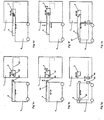
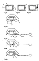
- a fundamental aspect to this disclosure of technology is the separation of patient support structures from the RF coil system. This is embodied in either a dedicated stretcher with dedicated tabletop system ( Fig 1B ) or the traditional tabletop system ( Fig 1A ) for use in an MRI (1).
- Fig 1A the patient (4) lies prone, with feet first into the MRI bore (head first may work as well) (2) in preparation for MRI breast imaging.
- a tabletop coil system (5) is placed on top of an MRI's stretcher and general purpose tabletop and, in the case of breast imaging, the patient lies prone atop this structure.
- a patient transport stretcher is used to attach to the magnet.
- the stretcher (7) is typically a wheeled stretcher which can mechanically attach (dock) to the magnet (1).
- the general purpose tabletop is used to roll the patient into the magnet bore (2) and moves relative to the stretcher.
- the tabletop is driven in and out of the magnet by various mechanisms.
- a cantilevered patient support that is separable from the magnet is used.
- Philips or Toshiba cylindrical magnets a removable patient support is introduced by a different type of transport stretcher.
- the implementations provided by all of these magnet manufacturers are not designed to accommodate a specialized imaging or intervention application or special patient positioning and therefore consist of a simple flat tabletop.
- a dedicated coil system attached to a special purpose tabletop which sits on top of the transport stretcher is used. An example of such a proposed arrangement is presented in Fig 1A .
- the electronics housed in these coil systems are electrically connected to the MRI RF acquisition system.
- Various methods of attaching to the MRI system have been proposed. At the time of filing of this Patent, the most common include 1) a wire connecting the coil system directly to the moving attachment of the MRI (General Electric implementation), 2) a wire connecting the coil system to the stationary part of the MRI (Philips implementation). 3) wire connecting the coil system to the MRI through connections provided in the patient support (Siemens implementation).
- Each of these means require the user to effect the connection of the coil system to the MRI by manually connecting a plug. Additional means could include electrical attachments that enable the wires to directly connect to the MRI without the operator needed to attach them.
- the process of setting the tabletop coil system on the patient support, or docking the patient support and stretcher to the magnet would perform the direct electrical connection to the MRI system. Electrical connection of the coil would be effected by the act of docking, or attachment of the stretcher, or tabletop coil to the apparatus. This may also include positioning the coil plug very close, but not completely in contact with the MRI connector. The user would then be required to perform the connection; however the benefit of positioning the connector close to the MRI connection would be to reduce the complexity of the setup process. This will become increasingly important when the number of required connections to the MRI (number of channels) increases.
- the tabletop contains a set of cables to be connected to the MRI. These cables may be connected to the MRI through a moving station (3) that advances to mechanically and/or electrically connect the tabletop to the MRI. Electrical connectivity ensures the coils in the tabletop are connected to the MRI RF acquisition system. Mechanical connectivity ensures the tabletop can be transported into and out of the magnet without damaging the electrical components.
- a means to facilitate RF cable connection of the RF coils to the magnet For magnets providing upwards of 16 data acquisition channels, it is highly desirable to provide a means to facilitate RF cable connection of the RF coils to the magnet.
- One such means would involve the specialized tabletop (tabletop designed for a specific, rather than general anatomic imaging function) to be attached to the magnet by way of a row of vertically or horizontally disposed RF connections with associated mechanical alignment.
- the RF cables from the coils within the tabletop would terminate at the horizontal face of the tabletop at the end proximal to the MRI.
- the RF cables would terminate in a way that they are directed in vertical face either directed upwards or downwards.
- Fig 1C demonstrates the tabletop and stretcher in the undocked position.
- Fig 1D demonstrates the table advanced into the magnet such that the tabletop (8) has been connected to the moving station (3) that supports a connection point (80) to the MRI RF system that corresponds to a connection point on the tabletop (80).
- Fig 1F demonstrates the tabletop with vertical connectors undocked from the magnet.
- Fig. 1F demonstrates the tabletop attached after the tabletop has either been lowered on the moving station, or the moving station has been raised to meet the tabletop.
- Fig 1G shows an alternative arrangement where the RF cables have been routed from the tabletop through the stretcher and from the stretcher into the magnet through connection points on the stretcher and magnet respectively (80). In this alternative arrangement the electrical connection of the tabletop to the MRI RF acquisition system is performed during the action docking the stretcher to the magnet.
- Connection of the RF electronics of the tabletop to the magnet either through the moving station (3) or through a connection on the stretcher to the MRI would involve i) mechanical alignment and attachment of the stretcher to the magnet through a mechanical docking sequence, ii) the tabletop advancing to connect to the moving station (3), or the moving station advancing to connect to the tabletop.
- Connection of the tabletop to the moving station would be done by first providing a means to mechanically align the two mating connections by way of pins and holes, tapered alignment features or the like, such that the connections are mechanically aligned before the electrical connection is established. This is an essential feature for an automatic connection to the MRI.
- These connectors can be coaxial connectors in which the center pin is shielded by an outer connector.
- the signal would be transmitted through inductively coupled connections. The signal could be transmitted through optic fibers. The requirements for a mechanical alignment means would be maintained for all connection strategies.
- the automatic connection of the table to the MRI through these electrical connections (80) through the moving station (3) or the stretcher is a useful concept having the benefits of reduced user interaction and provides a means to support a dense array of electrical connections (i.e. greater than 36 channels). Overcoming the electrical connector insertion force is significant when utilizing greater than 36 channels.
- a mechanism such as levers, cams, motorized linear or rotary actuators, or the like provides the required mechanical force required to facilitate connectivity to the magnet.
- Another aspect includes the addition of a cover that would protect the connectors from dirt, fluids, or patient/user contact. This cover would be lifted to protect the connectors automatically as the two sides approach each other. (For horizontal alignment, the cover would lift to cover the top of the connection area. For vertical alignment, the cover would lift to cover the side of the connection area). This cover would provide a mechanical barrier as well as a static charge barrier to protect associated circuitry.
- Additional coil connection means could also include attachment to a wireless device which transmits to the MRI.
- the invention as defined by the claims can be applied to all the various means of attaching the RF coil system to the MRI system.
- an automatic coil tuning circuitry system may be provided in the tabletop. This circuitry must be positioned between the coils on the tabletop and the connection to the MRI. Currently, no stretcher system provides an integrated automatic coil tuning system.
- a dedicated stretcher and tabletop system for breast imaging has been presented in the Prior Art (Piron et al, 2005/0080333).
- This system provides a unique patient support tabletop designed specifically for breast imaging and intervention.
- This system is presented in Fig 1b .
- the stretcher provides a large access volume underneath the breasts, giving the physician improved access to the breasts for imaging preparation and interventional applications.
- a description of a coil system is presented in which the coils are not integral to the patient support and can be detached. This concept can be expanded upon greatly to fully take advantage of the open architecture of the system and the separation of the patient immobilization and RF coil system functions.
- Additional support structures can be used to obtain optimized positioning of patient anatomies.
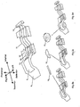
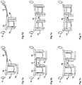
- a patient support structure and RF system for imaging a patient in a prone position is shown in Fig 2 .
- the main support structure (8) is similar for both the dedicated tabletop system and the stand-alone tabletop system.
- the figure shows how the two alternatives - placing a coil on top of the general purpose tabletop, versus replacing the general purpose stretcher and tabletop with a specialized, stretcher dedicated for a specialized tabletop which integrates or receives coil elements.
- the figures represent both the add-on tabletop version and the dedicated stretcher-based system similarly, though the tabletop add-on differs from the specialized tabletop in the length of the structure, where the dedicated stretcher/tabletop comprises a longer support for the entire length of the patient.
- the patient support structure (whether dedicated tabletop, or stand-alone) provides 1) structural support to position the patient in a comfortable position, 2) electrical cabling (11), 3) connectors and circuitry to enable connection/communication to the MRI system, 4) connections for secondary structural supports (14), 5) apertures to provide access room and to facilitate connection of substructures (9), 6) connection points (electrical and mechanical) to attach compression systems and immobilization devices. 7) Electrical connection of compression and immobilization devices.
- Coil elements can be integrated into the body of the structure as is currently done, or may be attached in a separable manner to the main support structure as claimed in this invention.
- the separable coils have electrical and/or magnetic connections, as well as mechanical connection to the main support structure. All signaling between the MRI and the coils takes place through the cables by way of the MRI connector (12). In the advent of wireless technology the signals would be transmitted via a similar wireless means.
- a secondary support structure (15, 16, 17) can be attached to the primary support structure (8) in order to optimally position the patient's tissues for imaging or interventional applications. These support structures hold a significant portion of the patient's weight and are integral to supporting the patient in a particular position.
- These structural elements are presented in Figures 2A, B, C .
- a sternum support (15) is shown attached to the support structure. This is the preferred configuration for bilateral imaging of the breast.
- This sternum support may house an RF coil and may be electronically attached (14) to the cables (11) of the system.
- a unilateral breast support (16) is demonstrated to position the unimaged breast out of the way.
- a bilateral breast support (17) is inserted into the support structure.
- This support provides two volumes in which the breasts can rest and are substantially immobilized without significant compression. It is preferable to provide multiple support sizes for various breast sizes. These supports would be provided in varying dimensions according to breast anatomy sizing. In the extreme case, supports would provide a small cup, or plate, which could be used to image mastectomy patient, or the male breast. Combinations of different coils for different breast sizes may be used with this configuration.
- This structure (17) may house RF coils for imaging of the breast and apertures though which the breast may be accessed.
- Secondary support structures may house additional RF coils.
- the bilateral support (17) may house a gradient coil, a transmit, receive or transceive coil. The ability to accept modular coil elements in an interchangeable support structure is a unique aspect of the present invention. Additionally, these secondary supports may provide specialized coils that facilitate specialized breast imaging, such as imaging or intervention of the axillary tail of the breast. This would include a lateral member that can be attached to the top of the compression frame on the inferior and superior portion of the compression, or patient support.
- a separable sternum support can be used to hold an array of RF coils, and also support the weight, or maintain the patient in a fixed position.
- This support can be separated from the main body of the system, while still being able to be positioned fixedly for imaging.
- a secondary plate can be positioned externally (from sides or below the breast). These would be positioned in fixed positions relative to the anatomy.
- a set of coils may compress the breast against the chest wall. In this configuration the coils may be used preferably to image mastectomy patients.
- this separable arrangement of coils provides a means in which additional coils may be provided at other locations on the structure.
- additional coils may be provided at other locations on the structure.
- a set of coils that are none-specific to breast cancer metastasis such as a body coil to scan various regions of the body.
- additional coils located in the primary support structure at locations such as near the liver, lobes of the lung, lymph nodes (neck, chest regions not covered by the breast coils, body, groin,) adrenal glands and brain may be provided.
- These coils would either be attached to the table for a specific patient, or would be selected during the scanning procedure for specific imaging sequences. In either case, this has not been presented in the prior-art for a specialized coil geometry. In one application these coils may only be selected for patients with a known cancer, while for the screening application, all available channels are used for coils positioned near the breast region as no-known cancer exists in these other regions.
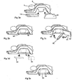
- Adjustable compression systems, anatomy support, positioning and immobilization devices are integrated in a separable manner to the patient support structure ( Fig 3 ). They also provide a basis for positioning and guiding imaging or interventional devices to an anatomy of interest.
- These compression systems (18, 19) may consist of flat plates as shown being introduced to the system in Fig 3A , or members having surfaces that conform to the anatomy or to a desired shape.
- These compression systems are movably and lockably disposed on tracks, rail guides, or held by mechanical arms or the like. Where multiple degrees of freedom are desired for plate adjustment, lockable joints such as gimbals having several degrees of freedom may be used, or a second guide rail may be mounted on top of a first (and a third on top of a second), permitting adjustment in multiple independent axes.
- a combination of mechanisms may be used to provide both linear and rotational adjustment. These positioning devices are locked in place using clamps, cams, mating threads, straps, friction fits, or other immobilization means. It is also possible to deliver or to maintain a patient supporting, immobilizing, or compressive force by coupling a mechanical, electrical, hydraulic or pneumatic actuator to the member.
- a mechanical, electrical, hydraulic or pneumatic actuator to the member.
- Fig 3C shows an anterior structural plate (20) that hinges in the sagittal plane, shown here hinged about the thorax region of the patient, and a lateral structural plate (21) that hinges in a coronal plane, shown hinged about the thorax region of the patient.
- These plates may pivot or slide into the volume of interest, or may be completely detached and reattached as required.
- These plates may be delivered and locked in place relative to the main support structure by various mechanical clamping or fixation means (22).
- These structures are brought into the structure's open access volume for purposes of: 1) protecting anatomy from rubbing against the MRI's bore as the patient is advanced to the imaging position, 2) providing attachment points and fixation means for other structures, imaging or interventional devices, 3) providing additional coil structure support and attachment points, 4) (when used with a special purpose tabletop having a dedicated stretcher) providing a structure and surface which may bear the tabletop's weight when advancing into the bore of the magnet, 5) for catching blood, or 6) for any combination of these purposes. It may also be preferable to communicate the locked or unlocked conditions of these plates through mechanical locking mechanisms, electrical signals or any other communication means to indicate to the magnet or the user if the plates are not in the proper position for imaging or for advancing to the imaging position. This provides a means to ensure the patient will not be advanced into the magnet until all plates are positioned appropriately.
- the compression plates (18, 19) additionally provide mountings to which removable RF coil systems (23, 24) or magnetic field gradient producing coils, or “gradient” coils may be attached. These mountings may provide both mechanical connections to the compression system and, simultaneously signal connectivity to the MRI imaging system, such that the act of connecting the coil element or elements to the movable compression plate also connects that coil's signals to the MRI.
- RF coil system that is separable from the main support, the secondary support structures and the compression/immobilization system is that the patient may remain in the identical position while various RF coil systems can be attached and removed. This is a unique and fundamental concept.
- RF coil systems may be attached to or built directly into the compression frames. These compression frames would then be connected to the main support structure both mechanically and electrically through a single locking/fixation means. There would be no need to attach a moveable coil to the MRI with a separate cable or other signal coupling means if the signal path is completed through the fixation or locking means. This may be accomplished by (for example) providing sliding electrical contacts along the adjustment range of the compression plate's fixation means. This connection could either be constantly in contact, or it could be closed by the act of fixing the coils in place with a suitable fixation means such as a clamp, cam lock, friction fit, or the like.
- a suitable fixation means such as a clamp, cam lock, friction fit, or the like.
- a plug referred to herein as a termination plug, provides electrical terminations for the end of a set of signaling cables or lines.
- a suitable plug configuration of various electrical components such as electrical shorts, opens or various loading (impedance from resistors, inductors or capacitors), along with appropriately mechanically arranged keyed coil plates, enables determination and routing of the channels to the MRI to happen automatically, with no need for multiplexing circuitry.
- each coil plate mates with the cabling system through an N terminal plug, where N is the maximum number of coils that can be included within each coil plate.
- each unused, terminated connection line of a coil plate can be wired in parallel with an active coil on a different connector, thus providing connection to a full set of active MR channels automatically. Unused lengths parts of the cable system are terminated when coils are plugged in to it. Also, a coil plate is proposed which has a connector which will reverse the polarity of its connection when it is physically connected in the opposite orientation.
- a coil plate may have a connector plug which may mate with a connector receptacle in a variety of different orientations (e.g., 0 degrees, 90 degrees, 180 degrees, intermediate degrees, etc), wherein the orientation of its connection determines which channels of the cable system (and therefore MRI) the coil plate connects with (and which cables are terminated).
- orientations e.g., 0 degrees, 90 degrees, 180 degrees, intermediate degrees, etc
- the compression/immobilization system should preferably consist of materials giving rise to minimal artifacts when imaging using other imaging modalities such as ultrasound, X-ray. PET, CT, optical, etc. This can be accomplished through appropriate matching of materials such that the excitation or detection of signals are minimally affected by the existence of the compression/immobilization system (i.e. acoustically transparent windows, optically transparent windows, optically translucent materials, radiolucent materials, non-magnetic materials etc).
- the antennae, or RF coils used with such an apparatus include transmit and receive coils of various designs.
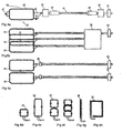
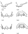
- a typical RF coil design for a simple receive-only loop coil is presented in Fig 4A .
- This RF antenna (33) consists of basic RF components including the RF coil conductor (25), broken into multiple segments with distributed capacitors (26). At one of the junctions is a passive blocking circuit (27), with an additional active blocking circuit (28) which is activated by a bias signal from the MRI.
- Various additional circuits and components are desirable and will be considered to be included when appropriate when referring to all RF implementations throughout this document.
- Preamplifiers and conditioning circuitry may be included either close to the coil as is preferred for optimal SNR, or further towards the MRI connector (12).
- the pre-amplifiers can be included either 1) on the MRI system, 2) on the support structure, or 3) on the coil. There are benefits to positioning the preamplifiers on the coils, as they can be easily replaced, can be optimized for particular applications and can provide greater SNR improvement the closer they are to the coil.
- current shield chokes or baluns (30, 31) or other like components may be placed on the cable, on the coil, or anywhere throughout the RF system to provide appropriate current chokes which minimize electrical currents in the shield of the RF conductors.
- Fig 4B When more than one coil is provided in the system there are many ways in which they can be selected.
- Fig 4B three coils are shown, decoupled from one another by an appropriate overlap which brings mutual inductance to zero.
- a multiplexer (34) can be used. This is a common way of selecting which coils are receiving or transmitting signals to the MRI when a subset of the full available set is required. This is well known in the prior art.
- Fig 4C two coils are shown with an electrical connector (44) in the cable (11). When the coils are detached from the cable, signals to or from the MRI can not be transferred. In this way various coils can be removed and interchanged as is appropriate.
- circuitry can be enabled, either mechanically through the act of detachment or electronically, which provides an appropriate signal or electrical characteristic on the cable to disable or detach that cable's connection to the MRI, or remove any effect that cable may have on the imaging system.
- small (35) or large (36) loop antennas provide high SNR and can be sized appropriately to the anatomy.
- Butterfly coils (37) can be combined with loop coils to form a quadrature configuration. This has been presented in the Prior art. Multilobe butterfly coils have not been extensively used in multiple coil geometries however.
- Microstrip Transmission line coils (38) (Zhang 2002/0079996) can be utilized in densely packed configurations in a variety of geometries. These antennas can be combined with loop and/or butterfly coils in densely packed arrangements while still providing substantially orthogonal fields that lead to high SNR and unique fields that can lead to high accelerations for parallel imaging.
- These microstrip coils can be fixed into loop, or hybrid structures to form that appropriate imaging sensitivity profile (39). Additionally opposed solenoid RF antennas can provide good local imaging with the benefit of minimal coupling with surrounding coils.
- a fundamental element to the invention presented herein is the ability to decouple a large number of coils in a confined space by use of combinations of coils which are intrinsically decoupled from one another.
- a combination of loop coil and butterfly coil may be positioned in such a way that they can be placed co-planar to one another and not be coupled.
- a loop and a butterfly coil exceeding at least 3 cm in its longest dimension can be positioned in a location crosswise from a loop coil, in a clinically useful geometry and not diminish imaging quality through significant coupling effects.
- coil geometries can be used that are conducive with a separable RF system design as presented (i.e.
- the RF coils must be embedded in a housing (40) that protects the electronics from damage, and protects the patient from potential bums or heating.
- the coil housing also provides an RF shield which can be integrated into the housing. Examples of such coil housings are shown in Fig 5A .
- the coil (33) consists of a coil housing (40), with the electronics embedded within the coil housing.
- an aperture (41) in the middle of the coil housing provides an access port in which interventional procedures may be performed.
- a cable (11) runs out of the coil housing as is common with most coils.
- a direct electrical/mechanical connection (42) can be made from the coil to cabling running to the MRI through various potential attachment points on the structure or on the compression plates as shown in Fig 5B .
- an optical signal may be used to transmit the received imaging information from the coil to the MRI. This is demonstrated in Fig 5C where an electrical/optical signal conversion takes place on the coil plate or in a structure which is connected to the coil plate and the optical signal is transmitted to the MRI via fiber optic cables or optical signals transmitted through the air. This conversion can take place inside an imaging tabletop or in a structure connected to the imaging tabletop.
- the MRI In connection with the optical transmission of imaging data, the MRI is fitted with a means of decoding or demodulating such data in order to process it in the ordinary way.
- Each of the coil housings presented must provide the following features: 1) Mechanical attachment mechanisms, 2) Means of coupling signal to the MRI, 3) Physical housing to protect electronics and patient which is impervious to fluids and may be appropriately cleaned and/or disinfected.
- coil housings or tabletops may also contain batteries or capacitors which would be used to operate coils that are wirelessly integrated into the RF system (e.g. using telemetry or an optical connection). If these coils are receive-only coils, a DC voltage is required to provide a blocking voltage to the coil during transmit imaging mode, or power may be required to activate amplifiers located in the electronics.
- the coil housing may include a means of connecting to a battery recharging station. This may be provided by way of an electrical connection to the coil housing from the recharging station, through the housing to a rechargeable battery internal to the housing. This battery may then be electrically attached to the coil circuitry where it can power connected amplifiers, or activate diodes to perform switching circuitry. Alternately, the coil may be powered by a fuel cell, which fuel cell may be recharged while in the coil housing, or which may be removed for purposes of replacement and/or recharging.
- Coils having cryogenic cooling may be refilled with cryogen using this same battery charging station, or a separate charging station.
- a coil housing may contain or integrate a cryogen containment device that contains cryogen coolant (e.g. liquid Helium, liquid Nitrogen) so as to reduce the electrical noise arising from the electronics and the coil conductor.
- cryogen coolant e.g. liquid Helium, liquid Nitrogen
- the cryogen levels in the coil would need to be recharged, or refilled over time due to the gradual loss of cryogenic coolant from the containing housing.
- a separable coil with such a cryogen container would benefit from a recharging station which refills the coil with cryogen (either on demand, automatically, or otherwise).
- This charging station consists of a cryogen containment volume and a means to supply this to the coil housing.
- cryogen When the coil is attached to this charging unit, it is filled with cryogen through an opening and a sealable valve contained in the coil housing.
- An additional concept would be to combine the battery charging and cryogen refilling functions into a single station. As such the battery levels used to charge the active components of the coil, and the cryogen levels used to cool the coil, can be refreshed in a single step. Additionally, such a coil having cryogenic coolant can use the Seebeck voltage effect to generate a small amount of electrical power. This power can be used directly to provide coil blocking or to power the transmission of signals from the coil, or the power can be used to charge a battery which is in turn used to do these things.
- RF coils may be integrated into the coil system through any combination of a variety of means, wherein only the separable ways of integration form part of the present invention: 1) Embedded (non separable) coils in the support structure, 2) Embedded coils in non-separable, but movable structures, 3) Separable RF coils in coil housings attached to the compression frames, 4) Separable RF coils in coil housings attached directly to the support structure, 5) Separable secondary support structures containing RF coils.
- embedded coils in case 1) and 2) can be directly connected to the MRI connector (12) by way of the traditional means of electrical connection.
- Separable coils 3), 4), 5) may be connected to the MRI via a connection panel (13) or port (14) provided within the support structure (8) which is then attached to the MRI connection (12) by way of electrical cables (11) (or other such means).
- RF coils that are attached to the moveable elements of the system such as the compression plates, the secondary infrastructure or embedded within the compression plates have the advantage of being placed very close to the anatomy resulting in high signal acquisition.
- Connection points are provided in the support structure at points that are accessible to the MRI technologist and located at various positions on the main support as indicated in Figures 5E , F, G and Fig 2 . These connections would consist of single or multiple individual electrical, optical or inductive connections housed within a mechanical support structure. In cases of arrays of densely packed RF coils, these connectors would consist of many independent connectors. RF coils may be attached to the connection panel or ports by way of multiple means including:
- connection points should provide mechanical integrity and in cases where the coils may be exposed to fluids or bio-contamination, must be impervious to these fluids and be easily cleaned and disinfected. Additionally these connection points should provide unique physical connections so that only certain coils can be connected to certain connection ports as appropriate.
- One exemplary implementation includes a number of sets of electrical conductors (88) disposed along two sets of sliding rails.
- the number of sets of electrical conductors is equal to the number of channels of the MRI system.
- a rail (84) supports a mechanical slider (86).
- multiple sets of multiple parallel conductors (88) in which each set terminates on a coaxial cable (89).
- each channel is represented by a set of three conductors, one centre conductor for the central conductor of the coaxial wire, another two used for the outer conductor of the coaxial conductor.
- the relative position and thickness of three conductors relative to each other enable matching of the conductor to enable impedance matching for the electrical system.
- multiple sets of two conductors are used, connected in alternation with inner and outer conductors of the coaxial cable. This alternation, whether among sets of three or sets of two conductors is necessary to provide a substantial degree of shielding between adjacent channels of the MRI signals.
- the slider (86) is fitted with brushes or spring contacts which connect electrically to the sets of parallel conductors either continuously, or only when the slider (86) is locked in place.
- the coil and coil frame (87) supports similar sets of parallel conductors (90) disposed along a different direction of adjustability of the coil frame. These conductors are positioned externally to the coil enclosure and connect to the coils housed within the enclosure. These conductors are aligned with a mating set of conductors contained within a T slot in the mechanical slider (86). When the conductors on this slider are locked into place with the coil enclosure by way of a locking mechanism, the two sets of conductors are in electrical contact.
- Such an arrangement provides a means of locking the slider and/or coil mechanically and completing the electrical connectivity between the coils (87) and the cables (89) in one action.
- Regardless of adjusting the positions of the coil frame in the slider and the slider in the rail there are multiple electrical connection from the coil contained in the housing to the wires that are connected to the MRI.
- T slots and a set of three conductors various other mechanical and electrical configurations may be used to connect a set of cables at continuously variable positions through mechanical positioning mechanisms. This ensures no cables interfere while positioning coil plates, and electrical continuity checking can determine if all plates in the system have been locked into position.
- Bilateral imaging applications such as breast imaging when using arrays of multiple coils can make use of a means of selecting subsets of coils to collect only MR signals from the volume of interest.
- a means of selecting a subset of coils during image acquisition of one breast, and another subset of coils for another breast is preferable. This is also required for imaging applications when selecting to image or excite sub-volumes of interest and additionally in applications where sets of transmit coils that only comprise a subset of the full number of RF coils may be desired to be activated.
- Methods of selecting or deactivating coils include selecting coils by electrical activation or deactivation, mechanical modification of the coil such that the coil circuit is modified, opened or closed or the removal and reconnection of coils.
- One means of switching coils for different imaging configurations pertains to the physical separation of the coil from the system, in particular the removal of the coil and coil housing from the connection to the MRI. If another coil or coil array is not put in place of the removed coil, a termination circuit, an open circuit, an appropriate resistive load, such as a 50 Ohm load, a closed circuit, or a circuit designed to detune the coil may be connected in its place, either automatically or manually. This can be applied to coils that are connected to the system by electrical connection, electrical/mechanical connection, inductively coupled or optically coupled coils.
- Another coil selection option includes electrical deactivation of the coil through a blocking signal (typically a bias voltage) to a detuning circuit. These coils may be selected so as to optimize the total number of coils which are imaging an appropriate volume. Electrical coil selection can be accomplished by 1) user selection of coil configuration files which program the MRI to send an appropriate blocking signal to the coils, 2) automated switching based on external signals generated through the MR control pulses., e.g. alternating activation and deactivation of coils in such a manner to decouple them appropriately or to maximize the number of active signals as is preferable with imaging of bilateral anatomy. 3) user selection through an external signal not provided through the MRI. This signal may be electrically, optically or inductively provided.
- a blocking signal typically a bias voltage
- one or more coils in an array is deactivated or disconnected or removed, it does not contribute electrical noise to the reconstructed image in the same way that an active, connected coil would. Additionally, it cannot provide unwanted coupling between other coils when thus negated.
- more coils are provided in proximity to the region of interest than can possibly be used simultaneously.
- Various means are used to select from among the available coil elements the most beneficial coil elements. The means of coil selection and schemes for coil deactivation are given above.
- Switching with external circuitry and multiplexing of channels, enables more coils to be used present in an array than the total number of available receive channels available on the MRI. For instance a 16 coil element breast coil array can be used with an 8 channel MRI. This concept has been proposed in the prior art, however this has not been considered for an expandable system as presented.
- This multiplexing capability can be provided in the dedicated stretcher-based or tabletop add-on coil as well as within the MRI electronics.
- switching circuitry can be integrated to enable proper transmission of the receive coil signals, transmit signals and blocking signals for coil deactivation as has been presented in the prior art ( 6,867,593 Menon et al ). Integrating this switching technology into the stretcher has not been anticipated in the Prior Art and offers significant advantages.
- mechanical/electrical switches may be used to force the circuit to be inactive. This is primarily a mechanical decoupling where the coils may be left in place, with a switch either completing or breaking the circuit, or enabling an additional circuit which disengages or decouples the coil from the system.
- multiple coils may be arranged within a coil plate in a manner that enables certain coils when the coil plate is inserted in a specific orientation, leaving the other coils inactive. This could be a gravity switch, which selects and deactivates predetermined coils depending on in which orientation the plate is fixed. Alternatively, coils could be activated/deactivated by the orientation in which the coil frame's connector is introduced into the corresponding receptacle.
- Combinations of loop coils, saddle coils, transmission line antennas, butterfly coils, dipoles, solenoid coils, opposed solenoid/self-inductive can be used in the present invention.
- These coils can be used as phased array or as quadrature or circularly polarized configurations. It is preferred to provide arrangements where multiple coils are selected on the basis of being sized appropriately to the patient anatomy, with each coil imaging substantially independent sub-volumes of the total imaging volume. In this way the combined signal to noise ratio from all the coils can be maximized.
- the combination of a loop coil, a butterfly coil and in some arrangements a transmission line coil all three lying in the same plane or in nearby parallel planes will form fields whose field lines are, in most places, close to orthogonal to each other. Having substantially orthogonal field lines helps to reduce inductive coupling between coils. In this way coils can be densely packed to cover an imaging volume without interfering with one another, giving rise to optimal SNR.
- Signals from individual coil elements can be combined in phased-array, quadrature or circularly polarized arrangements.
- the preferred examples are presented with interchangeable coil plates containing coils in phased array and quadrature arrangements in various geometries and various orientations.
- the arrangement of the coils on these plates contributes to the overall sensitivity profile and field-of-view of the combined coil array. Therefore the size, position, phase variation and orientation of the coils must be considered to optimize the overall sensitivity, field uniformity, field coverage, coil coupling and parallel imaging characteristics of the entire coil arrangement.
- Fig 6 shows a number of loop coils (36) arranged and permanently mounted together within a movable coil plate (40).
- a set of four loop coils are presented with long axis in the Y direction (corresponding to patient Anterior/Posterior orientation) in Fig 6A .
- the polarity of the field attributed to each coil is in the same direction. Decoupling of adjacent coils is performed by overlapping the coils slightly.
- Fig 6B the direction (polarity) of the field is reversed in alternate coil. In this manner the coils flux or field generated by the combined coils can be more effectively decoupled in some arrangements.
- a similar coil array to Fig 6A is shown in Fig 6C differing only in height where smaller coils are used (35).
- Fig 6B the aspect ratio is closer to 1:1 width to height, opposed to slender coils in Fig 6B , where the ratio is 2:1 up to 5:1 in dense arrays.
- Placement of the coils (36) in the horizontal orientation as depicted in Fig 6D demonstrates a four coil arrangement with the long axis of the coils aligned with the long axis of the coil plate.
- An arrangement of four butterfly coils (37) is presented in Fig 6E .
- These coil plates can also be arranged with loop coils as shown in Fig 6F , as they produce unique coil fields for better parallel imaging capability.
- Loop and butterfly coils can be overlapped such that their fields are orthogonal to one another. In this way a dense packing of 8 coils with unique imaging fields of view can be attained. These coils can be arranged with long axes aligned with the long axis of the coil plate as shown in Fig 6H . Transmission line coils (38) can be arranged with their length along the main magnetic field of the magnet as shown in Fig 6I . The lengths of these coils can be modified to fit the contour of a compressed breast. Alternatively, transmission line coils can be used in a configuration where the line is shaped into the geometry of a loop coil, but which loop is not actually closed. Two such coils are presented in 6J.
- the coil operates similarly to a single loop coil with the field directed in one direction.
- this geometry is beneficial when considering these coils can be used in an array where the coils are positioned with their ground planes directed towards each other.
- Loop coils and transmission line coils can be combined to create dense arrays of coils as shown in Fig 6K where 8 coils are presented. Further, butterfly, loop and transmission line coils can be arranged to create a twelve coil array in which the fields are relatively independent. This arrangement of densely packed coils leads to arrangements of coils optimally sized to the anatomy of interest and providing for high acceleration factors with respect to parallel imaging capabilities.
- phased array configurations have been used for cardiac coil systems in which two rows of coils are used in order to provide for parallel imaging (e.g., SENSE) accelerations in two directions along the coil plate.
- a breast coil combining many loop, butterfly and saddle coils has been presented, however this is in a fixed arrangement ( Qu et al, US 2005/0104591 A1 ) where positions and types of individual coil elements cannot be modified.
- coil systems have been presented in which individual coil elements are shown to be combined in linear arrangements (Vij, US Patent 6,498,489 ). However no attempt has been made to decouple the imaging and support functions of the coils and there has been no attempt made in which to decouple the sets of coils from one another. Additionally, none of the coil arrangements presented in Fig 6 have been proposed in the context of imaging with the plates on opposing sides of the imaging volume.
- the TIM® system developed by Siemens Medical combines multiple coil elements, some of which are embedded within the patient support table.
- the MRI system actively blocks and detunes some elements in the array of coils. This is a significantly different concept than proposed.
- the TIM® system is a generalized RF system design in which the generalized tabletop has been developed to handle all potential imaging applications without specifically providing for optimized coil arrangements or positioning. Applications such as breast imaging require a dedicated support structure in which modular coil arrangements can be utilized.
- Fig 7A presents a unilateral breast imaging application where a single breast of interest is immobilized and compressed between two compression plates which can be adjusted in a left/right direction and locked in place, while the other breast is compressed against the chest wall by a contralateral breast support.
- medial (47) and lateral (24) coil plates are supported by a pair of compression frames. The ability to move these coil plates close to the breast significantly improves coil reception. Implementations of such a coil configuration have been presented in the Prior Art, various geometries of these coils were not detailed (Piron et al, 2005/0080333). This application presents detailed coil arrangements that can be used with such a configuration, and additionally expands beyond this concept with coil arrays presented in various other arrangements and geometries that enable improved coil decoupling.
- a bilateral coil geometry is presented in which two lateral compression plates (24) contain coils and two medial compression plates contain coil plates (47). Additional" anterior coil plates (23) can be attached to the compression frames or attached to the main support structure (8), as well as posterior coil plates, or coil structures (46) which are disposed against the chest wall, having large apertures which admit the breast. These coils may also be moved relative to the support structure. In the preferred embodiment the medial/lateral coils will primarily move left and right, while the anterior/posterior coils will primarily move up/down.
- a small adjustment range of the medial-lateral plates in the anterior-posterior direction up to 30 cm for standard breast imaging
- a left-right adjustment range for the anterior-posterior coils up to 50 cm for standard breast imaging
- four separate lateral-medial compression plates provide compression for both breasts.
- Additional support can be provided by a sternum support (15), which may or may not contain RF imaging coils. In this arrangement a total of 8 coil plates may be arranged to cover imaging of both breasts.
- coils may be attached to any other coil in the system through a mechanical connection. This may introduce the coil into the array at a well defined position such that it provides improved decoupling between coils.
- the connection can be made at various left/right positions such that various electrical connections associated with unique mechanical positions such that unique decoupling and electrical connections can be made.
- Coil plates may house transmit, receive or transceive coils, or any combination of these coils.
- the two posterior coil plates (48), the sternum support (15), the two medial coil plates (47) are combined into one combined support and imaging structure.
- This medial support structure can be removed from the main support as would be necessary for interventions performed in the medial direction to ensure full breast access.
- the medial support structure may also be hollow, such that various RF coils can be placed into position while that patient is still atop the structure.
- medial compression plates do not house any medial coil plates. Instead all of the RF antennae are integrated into this medial support structure.
- This arrangement may have coils on each medial face, in the sternum face, and throughout the posterior structure. In this arrangement the coils can be decoupled from one another through traditional means as the coils do not move relative to one another. This can be extended to include any combination of coil plates and support structures.
- FIG 7D An alternative arrangement of coils is demonstrated in Fig 7D , E, F. Here the function of compression of the breast and the placement of the coils have been separated.
- FIG 7D An implementation for a unilateral coil geometry is demonstrated in Fig 7D , the lateral coil (24) is attached through connecting members to the medial coil (47).
- These connecting members may i) house electrical connectors that complete circuits on the lateral or medial coil arrays such that they are activated for imaging, ii) may provide connections between lateral and medial coils for purposes of decoupling lateral and medial coils, iii) may house additional coils or segments of coils that can be used to contribute to the array of active coils.
- coils positioned in the posterior or anterior positions relative to the breast can be integrated at fixed positions relative to (24) and (47). In this way the coils are at known positions relative to each other, where decoupling strategies such as inductive or capacitive decoupling can be used to reduce the coupling interactions between all coil elements.
- Compression members can be attached to the members connecting the lateral and medial coils such that the breast may be compressed without moving the coils.
- a bilateral implementation extends this concept to attach lateral coils (24) to a large medial coil which can house coil elements in the posterior and medial positions relative to the breast, where the compression plates can move relative to the coils to enable compression as required.
- the posterior coil is integrated with the medial coils. In this arrangement all coils are at known positions to one another and therefore can be appropriately decoupled. No compression plates are presented in this implementation. The ability to numerous connect subsets of coils into a primary set of coils that is attached to the MRI is a fundamental concept.
- the lateral, medial, anterior or posterior coils can be interchanged with other coils such that the coils can be arranged such that they can be sized as is appropriate to the geometry of the breast.
- a set of various coils may comprise a kit that enables imaging of various breast sizes, including: One example involves coils for unilateral imaging and different coils for bilateral imaging. Additional implementations include unilateral and lateral coils that may be provided in a set of coils of different sizes including the following options: In one embodiment there will be coils provided in one size for a medium sized breast. In another embodiment there will be two sized breast coils for medium and large sized breasts. In another embodiment there will be three sizes of breast coil for small medium and large sized breasts.
- Other embodiments include more than three sizes of breast.
- the size of the coil would be primarily changed in the Anterior/Posterior direction.
- the range of sizes for these coils in the anterior/posterior direction would be (large coil - 20-25cm, medium coil 20-15cm, small coil 15-7.5 cm).
- An appropriate coil dimension in the superior/inferior direction as a combined set would be 15-25cm and would not vary more than 50% of the total size according to small to large coil designation.
- one of these breast coils will be in a configuration that is optimal for mastectomy imaging.
- the coils would be positioned in the plate parallel to the chest wall.
- the field of view of these coils would range from 20-35cm, depending on patient size.
- the optimal arrangement is such that the depth of the field of view of these coils is small and does not penetrate deep into the chest wall region, such that the ratio of the field of view to the imaging depth of the coil may be better 5:1 to 20:1.
- Various coil arrangements may be used to cover this field of view, including a set of butterfly, loop and transmission line coils such combinations are presented in Fig 6 .
- Optimally loop coils in the array would consist of coils longer than wide (aspect at least 2:1) directed with the long axis in the direction of the main magnetic field, parallel to the chest wall.
- Butterfly coils would optimally be directed with the long axis directed from patient left to right, while transmission line, or strip-line coils would be directed with long axis along the main magnetic field.
- These coil plates are provided as straight, or curved to match the chest. Patient may be supported by the primary structure of the bed such that the mastectomy region or surgical scar. Alternatively these plates could be made of a flex circuit such that the coils conform to the chest anatomy. The concept of using a kit of coils of different sizes is unique.
- a set of coil plates can be arranged as either a set of four moveable plates ( Fig 8A , D, G, J) 2 movable plates with 1 fixed medial array ( Fig 8B , E, H, K) or one fixed medial array with two attachable lateral plates ( Fig 8C , F, I, L).
- butterfly either with two or more lobes
- Fig 8A both medial and lateral plate can move relative to each other.
- Demonstrated in Fig 8A are two large lateral loop coils, with opposing medial butterfly coils.
- the medial coils may be comprised of transmission line coils such that the ground planes on the facing sides of the medial coils ensure these coils do not couple, thus improving performance of the coil array.
- butterfly coils may be used as lateral coils and loop coils as medial coils.
- one butterfly coil can be used laterally, one medially on the opposing side, while loop coils can be used opposed to these butterfly coils. In this way all coils will be decoupled.
- FIG 8B An alternative geometry is presented in Fig 8B , where the medial coils are attached to the same structure and overlapped or decoupled using circuitry. In this configuration the medial coils cannot be moved relative to each other.
- Fig 8C the medial and lateral coils cannot be moved relative to each other, instead they are locked together in a fixed geometry. Represented in 8C is a planer geometry, whereas in Fig 8F,8I and 8L the lateral coil geometry is curved.
- Fig 8A, 8B, 8C all represent 4 coil geometries
- Fig 8D, 8E, 8F are 6 coil geometries.
- the preferred geometry for Fig 8D and 8E are two lateral loop coils, decoupled from one another, with one large medial butterfly coil directed towards each loop coil on each side of the breast.
- the medial butterfly coil should extend and bend towards the chest wall with one lobe of the butterfly larger than the other.
- the lateral coil should be positioned more posterior relative to the medial coil so as to access the patients chest wall and axial.
- the use of a butterfly that has a non-symmetry lobe presentation and that bends towards the chest as presented is essential for proper imaging of the sternum area.
- the medial coils are decoupled by overlapping, while the lateral coil has two large apertures to enable access to the breast.
- the lateral coils attach to the medial coil at a number of connection points. These attachment points may be used to select, or activate coils in the medial array, where the coils are selected based on which coils are used laterally. Alternatively these connection points complete coil geometries by way of adding a conductor element to the medial or lateral coil arrays through the process of connection of the lateral and medial sections.
- Fig 8G, 8H represent 8 coil geometries where three lateral coils are used and one medial butterfly coil per side.
- Fig 8H shows a non-symmetric butterfly coil where the posterior portion of the loop is larger than the anterior (lower) part of the coil. In this way the lateral and medial coils are decoupled when the lateral coil is positioned more posterior than the butterfly coil.
- Variations of such a geometry includes decoupling the lateral coils from each other through i) overlap in excess of the required amount between the central and outer coils with corrective inductive or capacitive decoupling, ii) overlap the exact amount between the outer and central coils with no required inductive or capacitive decoupling, iii) overlap less than the required amount with corrective inductive or capacitive decoupling.
- Fig 8I shows two medial coils per side with numerous coils contained in the lateral coil attachment.
- several attachment points serving as both structural and electrical connections, are presented in the superior and inferior locations each per side with an additional connection anterior to the arrangement. This way multiple electrical connections may be made between the lateral and medial arrays. Any number of connection points may be used.
- Fig 8J demonstrates two lateral and two medial coils.
- the lateral and medial coils are slightly overlapped for decoupling. Any combination of loop and vertically oriented butterfly coils are intrinsically decoupled in this geometry.
- eight medial coils are located per side with eight lateral coils.
- This geometry is easily expanded so as to include numerous, vertically oriented loop coils and butterfly coils.
- each coil covers the breast in the Anterior/Posterior direction, while coils have limited field of view in the Superior/Inferior direction, which enables parallel imaging in the left/right and superior/inferior direction. These two parallel imaging directions are optimal for breast imaging in the prone orientation.
- Fig 8L demonstrates a final geometry where the mechanical/electrical connection can be made from the anterior approach so as not to risk pinching the patient as the coil is connected.
- Additional very high densities of coils can be used in the proposed coil arrangements.
- the addition of coils in the posterior region, with a large aperture for admitting the breast (s), and/or addition of coils in the anterior regions provide various alternative placements for coils within the presented coil configurations.
- the magnetic flux lines associated with the coils arranged on these coil geometries would be orthogonal to the main magnetic field of the MRI (B 0 ), so as to maximize collection of the MRI signal.
- a bilateral geometry could be presented where 8 butterfly coils may be located on the medial coil plates, or in the medial sternum support. Across from these butterfly coils could be 8 loop coils. This is repeated for both left and right breast volume. These coils would be longer in the anterior direction than in the superior direction, and decoupled pair-wise from each other on their respective coil plates. For a unilateral arrangement, 16 coils could be used per coil plate.
- the geometries of the coils can be slightly modified so as to differentiate their coil sensitivity profiles. This is performed by modifying the butterfly trace by extending the width, height, or angle of the conductor traces.
- This arrangement can be scaled up or down from anywhere from 1 coil per plate, to 16 coils per plate, while still maintaining sufficient penetration into the breast tissue over the clinically relevant field of view.
- This provides an arrangement where a very highly parallelized geometry can be used for breast imaging.
- transmission line coils can be used in either in a hybrid loop geometry as a replacement for the loop coils in the previous description, or transmission lines in a straight configuration, used in combination with the loop coils.
- curved or conformal coil plates may be utilized. Such plate arrangements may be useful when imaging other anatomies such as knees, elbows, wrists, ankles, etc. Interchanging these coil plates provides for all of the advantages discussed thus far for breast imaging, because it is hereby possible to support or immobilize the anatomy, advance to the scan position for imaging, return to the home position (outside of the magnet), and remove the coil plates either for access to the tissue or to replace them with an alternate set of coil plates and then re-image in order to optimize imaging and to provide the ability to deliver additional imaging and interventional devices without moving the anatomy from the configuration in which it was initially imaged.
- Specific Absorption Rate refers to the rate of energy deposition in tissue due to RF pulses transmitted by the MRI. Transmitting with relatively small local coils reduces tissue heating compared with transmitting RF through the entire body).
- the anterior and posterior coil arrays can be used as transmit coils, where the combined fields provide a substantially uniform transmit field, while the medial and lateral coils can be used as receive coils. The roles of the coils could also be the opposite, where the anterior and posterior coils receive and the medial and lateral transmit.
- the imaging methods presented can be performed with any combination of plate geometries. These plates may be arranged in a manner that they can move relative to one another, or may be fixed relative to one another. In the preferable arrangement these coils would be positioned as close to the anatomy as possible, while attempting to minimize coupling between coils. Coupling can also be minimized by sizing the coils appropriately to the anatomy being imaged. By selecting and attaching coil elements whose sensitivity profile is just sufficiently large to image the desired volume, but which does not extend far enough to couple to other coil elements.
- An alternate example of a reconfigurable coil array comprises a circuit board having multiple layers of conductive traces, which traces are insulated from one another. These traces, along with their attendant capacitors, inductors and blocking circuitry constitute individual coils, such that a multiplicity of coils is present on a single plate. These coils may be loop, butterfly, opposed solenoid, or transmission line types. Means are provided in this example for selection and signal connection of one or more of these coils at a time, while a number of other coils are disabled by being opened (electrically), detuned, blocked or short circuited.
- This coil selection means may comprise mechanical switching of conductive pathways or solid state electrical switching, either at the coil end or the MRI end of the signal coupling means.
- the act of mechanically affixing the coil plate to a fixation means could activate and deactivate selected coil elements on the coil plate.
- the fixation means could effect this activation and deactivation using mechanical keys or electrical plugs that connect some coil elements and detune, terminate or block others.
- each coil would interface with a receiving connector integrated with the mechanical fixation means.
- This pair of mating connectors could be shaped to accept connection one or more positions, so that the orientation in which the connectors meet determines which coil elements are active, and/or determines the polarity of each coil. For example, rotating the coil plate 180 degrees before plugging it in would reverse the polarity of the coil's output. Means would be present in the connector and blocking network to ensure that the blocking signal used with receive-only coils always arrived with the correct polarity.
- a patient can also be imaged with breasts in various geometries through compression provided from several directions.
- the concept can be extended to other anatomies that are reconfigured to suit a clinical or diagnostic need - i.e. it may be desirable to image in one anatomical configuration for optimal image quality, and in another to obtain images in a configuration representative of surgery, for example.
- a breast may be compressed towards the chest wall using a compression plate (18) that can move in the anterior/posterior direction.
- the plate presented in this figure also provides an aperture which is covered by a compression membrane (53). Within this plate there may be a coil plate inserted as depicted in Fig 9b .
- this compression plate containing the coils By moving this compression plate containing the coils close to the breast, good immobilization and high SNR can be obtained.
- an ultrasound transducer can be used to image the breast, while the four sides of the breast remain accessible for interventional purposes.
- This concept is shown in Fig 9C . in a bilateral imaging application in the axial view, and in the sagittal view in Fig 9D .
- An alternate compression plate is shown in Fig 9E , where the compression plate consists of a pivoting oblique member (55).
- each of these compression members there are one or more or apertures in which coil plates can be fixed, and one or more membranes (which may have coils removeably fixed across them). This is demonstrated in the sagittal view in Fig 9F .
- the benefit of this arrangement is that the breast is more completely immobilized and the immobilization system can support a greater number and variety of coils.
- the compression plates may also support a conformal plate such that the breast is more evenly compressed in the orientation.
- a conformal immobilization plate (56) or membrane (such as a thermally setting mesh) could be positioned on the breast while the patient is in the position used for surgery, such as the supine position as indicated in Fig 10A .
- the patient's breast position could be maintained while the patient is rotated to another position, such as the prone position, and positioned on the main support structure of a dedicated stretcher-based coil, or a tabletop add-on coil.
- the open architecture of the system provides for the addition of such a conformal immobilization structure.
- a set of imaging coils may be added to these plates, either as a coil supported by an oblique compression plate (72) as shown in Fig 10B , or as a conformal arrangement of coils supported on the conformal immobilization plate (56). This same arrangement is shown in Fig 10c in a sagittal view where the oblique compression is capable of moving up/down and rotating.
- the ability to position the breast in two different conformations while the patient remains on the main support structure is important for MRI interventions and when imaging may be required for determination of pre-surgical breast cancer extent.
- the repositioning should be done such that a set of MR images may be obtained while positioned in a standard imaging orientation (i.e. uncompressed with the patient prone, or compressed in the medial/lateral orientation with the patient prone), and a set of images that may be similar to the position during surgery (patient laying supine). This way the tumor position can be correlated between both positions, or in positions in-between the two end positions.
- Fig 10D where a compressed breast is demonstrated in an axial view compressed in a medial/lateral direction, and a localization wire (58) has been positioned through the lesion (57) of interest.
- Fig 10E all coils and compression plates are removed and the breast can be freely manipulated with the patient on the apparatus.
- An anterior conformal compression plate can then be introduced as presented in Fig 10F to compress the breast into a conformation similar to that of breast surgery, and to deliver a coil plate into proximity with the breast for imaging.
- the breast can be compressed in a preferred orientation for a particular clinical application, and RF coils can be positioned as close to the breast as possible to ensure high SNR images can be acquired.
- FIG 11A Another example includes body imaging applications.
- a dedicated body imaging stretcher (61) with a large interventional volume provides an access point in which modular support structures and coil arrangements can be positioned, affixed and removed.
- Applications for this system include cardiac, lung, musculo-skeletal, spine, liver and kidney imaging, as well as interventions for these anatomies.
- Fig 11A the patient (4) is supported by an MRI body support structure (60) where anterior (62) and posterior plates (63) are used to position coils close to the patient.
- various coil arrays can be introduced by way of coil plates.
- Demonstrated in Fig 11B is a large field of view coil array (64) and a small field of view coil array (65), typically used for higher SNR imaging applications.
- the coil plates are inserted into the support plates as demonstrated in Fig 11C .
- the small field of view coil array is put in place of the large coil array, and positioned appropriately over the target anatomy, so as to image with high signal to noise in a region of interest.
- coils tuned to different frequencies, optimized for a particular imaging or intervention application may be easily interchanged while the patient is maintained in the same conformation.
- a coil array may be required for contrast-enhanced imaging of blood flow as well as imaging hyper-polarized gas or the like for imaging of ventilation.
- a coil may be provided to excite or image a particular species associated with a novel intravascular contrast agent.
- Each of the coils can be appropriately tuned to detect, or to excite a particular species of interest.
- Additional lateral or oblique plates may be integrated into the apparatus as required. These plates may provide lateral support for a patient, provide attachment points for probes and devices, and may provide additional attachment points for coil systems for improved imaging.
- the support plates may provide access apertures and/or guidance means for intervention, or imaging with other modalities (X-ray, Ultrasound, Optical, Infrared, etc).
- X-ray, Ultrasound, Optical, Infrared, etc. X-ray, Ultrasound, Optical, Infrared, etc.
- a dedicated prostate stretcher and tabletop system provides additional access to enable modular coil and patient support apparatus to be reconfigured for various stages of the same imaging/intervention procedure, for procedures with different patients, or for different types of procedures.
- the major differential feature as presented is the addition of a support apparatus that can be inserted inside of the patient.
- the support apparatus not shown in this figure may consist of an articulating arm or support which holds a sheath or introducer into the body.
- an anterior coil support (62), a posterior coil support (63) and an internal coil sheath (68) all support a variety of coil arrangements.
- Various coil plates can be introduced to these support/immobilization structures depending on the application.
- the anterior plate (62) holds the patient's hips in a fixed position, while providing a means of attachment for the coil array.
- This may be effected by a support arm which maintains the position of the anterior coil and prostate sheath so that they are held at a fixed position relative to the patient.
- the prostate sheath may be permeable to various imaging modalities such as ultrasound and may provide interventional access ports to facilitate intervention of the prostate.
- the sheath (68) may also be made from a flexible membrane which can be expanded. In this way, a probe can be inserted into the sheath and be inflated or mechanically enlarged so as to immobilize the surrounding anatomy.
- the solid plastic walls of the probe should be expanded so as to press against the rectal wall. In this way the coils can be positioned in very close contact to the prostate so as to maximize signal acquisition.
- the plastic is made from a material with susceptibility close to that of the tissue, then there will be no deleterious image artifacts that may affect imaging of the prostate area.
- a vent or aperture should be provided in the center of the coil, or on the outer regions of the coil such that gases can be vented during the procedure to improve patient comfort and limit peristaltic motion.
- the presented technology includes a patient support structure for a patient comprising a connected or continuous area that support at least the head, chest, abdomen and legs of a patient, the support structure having at least one component support structure that receives and releases at least one RF coil system adjacent the patient, the at least one component support structure allowing positioning of the at least one RF coil system adjacent one or more of the head, chest, abdomen and legs of the patient.
- the patient support structure may have at least one specific component support structure for coils for at least one location on the patient support structure that accommodates at least one of female breasts, female genitalia or male genitalia.
- There may be at least one location of the component support structure has the component support structure has a glide support for enabling insertion of different coil structures on supports with common glide engaging features.
- the patient support structure may have at least one location of the component support structure with a glide support for enabling insertion of different coil structures on supports with common glide engaging features.
- the patient support structure may have coil structures with an engaging element that connects to a communication port, material flow port or power port on the patient support structure.
- the patient support structure may comprise a stretcher on wheels, and the stretcher may have engaging elements for engaging the RF coil system of the stretcher to the RF system on a magnetic resonance imager.
- the patient support structure may have a specific location accommodating positioning of female breast therein, the location is adjustable to accommodate breast of different sizes, and an RF coil system for assisting in the MR imaging of breast positioned in the location may be removed and replaced while breasts are positioned in the location without moving the compression system while in contact with the surface of the breasts.
- the patient support structure may have coils of different functionality selected from the group consisting of receiver antennae, transmitter antennae and transceiver antennae may be interchanged or placed in combinations of said antennae adjacent the location.
- the patient support structure may have at least one location with distributed thereabout a combination of transmission line coils, with the longest dimension in an anterior or posterior direction, disposed with loop and butterfly coils as alternating patterns on a) opposing plates, b) opposing structures, or c) co-planar on a plate.
- the patient support structure may have the at least one set of RF coils with at least two or at least four moveable lateral and medial coil plates containing intrinsically decoupled coils.
- the patient support structure may have the intrinsically decoupled coils selected from the group consisting of a) vertically oriented butterfly and loop coils, b) various transmission line coils with loops, c) transmission line coils and butterfly coils, d) multiple lobed butterfly coils in combination with a loop or transmission line coil, or the intrinsically decoupled coils are selected from the group consisting of a) horizontally oriented butterfly and loop coils, b) various transmission line coils with loops, c) transmission line coils and butterfly coils, d) multiple lobed butterfly coils in combination with a loop or transmission line coil.
- the patient support structure may have the RF coils enabled for signal transfer from the RF coils through attachment of the RF coils of the patient support structure to cables in an MR imager through at least one of:
- the technology includes a method of performing an MRI imaging process on an individual subject comprising supporting the subject on the patient support structure of claim 1, adjusting the location to accommodate dimensions of the individual subject, positioning at least one set of RF coils adjacent the adjusted location, moving the support into the bore of an MR imager, and providing MR image data on the individual subject that is at least enhanced by data derived from the at least one set of RF coils.
- the at least one set of RF coils is engaged to an RF system in the MR imager.
- the RF system of the stretcher automatically communicatingly connects to the RF system of the magnetic resonance imager.
- an additional step is performed that is selected from the group consisting of automatically tuning of coils in the stretcher, pre-amplifiers in the patient support structure enhance signal reception, electrical shimming-coils, sending RF signals by wireless signal transmission to a receiver external to the magnetic resonance imager and cryogenically cooling the coils in the patient support structure during MR imaging.
- the patient support structure may have at least one set of receiver antennae, transmit antennae and transceiver antennae which are exchanged at the at least one location.
- This technology details specific coil arrangements, means of connecting these coils and utilization of these coils for specific imaging purposes. Additionally, the concept of interchangeable coils has been extended and includes the use of a charging station for electrical power, and for cryogen cooled coils, the use of cryogen filling stations. Additionally, the present system enables the ability to embed electronics into the patient support and stretcher electronics to facilitate advanced imaging application such as: automatic coil tuning of coils, pre-amplifiers for signal reception, electrical shimming coils, wireless signal transmission devices and cryogen cooling systems for the coils.
- the RF antenna set includes interchangeable coils where the coils are coils tuned for different imaging species for a particular field strength and coils tuned for different field strength. Furthermore the RF antenna set may include interchangeable coils where the coils are sized to the patient anatomy including coils for:
- RF antennae a set of some of loop antennae, transmission line antennae and/or butterfly antennae.
- the coil configurations presented and combinations of configurations include the use of arrays of coils on separate plates that are intrinsically decoupled from one another through the use of butterfly coils facing loop coils, or loop and transmission line coils.
- the combination of vertically (longest dimension in the anterior/posterior direction) disposed loop and butterfly coils either in alternating patterns on opposing plates, on opposing structures, or co-planar on a plate, are also useful combinations of coil geometries. This geometry is intrinsically decoupled.
- decoupled or “inherently decoupled” "or intrinsically decoupled” is well understood in the Rf coil art.
- the magnetic fields resulting from stimulation of the coils are not significantly in interference with each other.
- the fields are not 180 degrees in opposition, and that the field strength of each field is at least about 50%, preferably at least about 70%, more preferably at least about 85%, and most preferably at least 90% or 95% of the strength of a single field in the absence of any other fields.
- the combination of transmission line coils (longest dimension in the anterior/posterior direction) disposed loop and butterfly coils either in alternating patterns on opposing plates, on opposing structures, or co-planar on a plate are also useful combinations of coil geometries. This geometry is intrinsically decoupled.
- the combination of butterfly coils and/or loop coils positioned in such a way that the top of the butterfly and/or loop coil is curved towards the chest wall is a useful structure.
- the combination of butterfly coils in a fixed medial support structure such that the left and right sets of coils are substantially decoupled through the use of overlap, capacitive or inductive decoupling is also a useful structure.
- the combination of any of the above coil geometries with the use of volume coils is also a useful structure.
- the combination for the preferred sets may also be selected from the set of the following coils for bilateral imaging:
Landscapes
- Health & Medical Sciences (AREA)
- Life Sciences & Earth Sciences (AREA)
- Surgery (AREA)
- Engineering & Computer Science (AREA)
- Physics & Mathematics (AREA)
- General Health & Medical Sciences (AREA)
- Veterinary Medicine (AREA)
- Pathology (AREA)
- Biomedical Technology (AREA)
- Heart & Thoracic Surgery (AREA)
- Medical Informatics (AREA)
- Molecular Biology (AREA)
- Public Health (AREA)
- Animal Behavior & Ethology (AREA)
- Nuclear Medicine, Radiotherapy & Molecular Imaging (AREA)
- Biophysics (AREA)
- Radiology & Medical Imaging (AREA)
- Oral & Maxillofacial Surgery (AREA)
- General Physics & Mathematics (AREA)
- Condensed Matter Physics & Semiconductors (AREA)
- Vascular Medicine (AREA)
- Neurosurgery (AREA)
- Immunology (AREA)
- Computer Vision & Pattern Recognition (AREA)
- Endocrinology (AREA)
- Gynecology & Obstetrics (AREA)
- Reproductive Health (AREA)
- Magnetic Resonance Imaging Apparatus (AREA)
Claims (10)
- Bobine RF pour utilisation avec un scanneur IRM (1) capable de générer un champ magnétique principal pour effectuer une imagerie de poitrine RM et qui peut être connecté à une structure de support (8), comprenant :un premier réseau de bobines RF (23, 24) positionnable de manière adjacente à un volume d'intérêt, comprenant une première pluralité d'éléments de bobines RF (35, 36, 37, 38, 39) disposés dans une géométrie sensiblement coplanaire, le premier réseau de bobines RF (23, 24) étant capable de recevoir un signal RM orienté dans une première direction, dans laquelle la première direction est configurée pour être orthogonale au champ magnétique principal du scanneur IRM ;un second réseau de bobines RF (23, 24) positionnable parallèlement au premier réseau de bobines RF (23, 24) de sorte que le volume d'intérêt se situe entre le premier réseau de bobines RF (23, 24) et le seconde réseau de bobines RF (23, 24), le second réseau de bobines RF (23, 24) comprenant une seconde pluralité d'éléments de bobines RF (35, 36, 37, 38, 39) disposés dans une géométrie sensiblement coplanaire, le second réseau de bobines RF (23, 24) étant capable de recevoir le signal RM orienté dans une direction sensiblement orthogonale à la première direction et sensiblement orthogonale au champ magnétique principal du scanneur IRM ;au moins une première plaque de compression (18, 19), dans laquelle le premier réseau de bobines RF (23, 24) peut être rattaché à la première plaque de compression (18, 19) ou en faire partie intégrante ;un premier dispositif de positionnement configuré pour raccorder de manière amovible et verrouillable la première plaque de compression (18, 19) à un premier guide de la structure de support (8) et pour pouvoir y être soumis à une translation ;au moins une seconde plaque de compression (18, 19), dans laquelle le second réseau de bobines RF (23, 24) peut être rattaché à la seconde plaque de compression (18, 19) ou en faire partie intégrante ;un second dispositif de positionnement configuré pour raccorder de manière amovible et verrouillage la seconde plaque de compression (18, 19) au premier guide de la structure de support (8) et pour pouvoir y être soumis à une translation ; etla première et la seconde pluralité d'éléments de bobines RF (35, 36, 37, 38, 39) étant configurés pour être orientées de manière sensiblement parallèle lorsque le premier et le second réseau de bobines RF (23, 24) sont raccordés à la structure de support (8) et la première et la seconde pluralité d'éléments de bobines RF (35, 36, 37, 38, 39) étant sensiblement désaccouplés l'un de l'autre au plan inducteur au cours de l'imagerie RM, dans laquelle la première et la seconde pluralité d'éléments de bobines RF (35, 36, 37, 38, 39) sont chacune configurées pour être séparables de la structure de support et chacune imbriquées dans un premier et un second boîtier respectifs fournissant un écran RF qui est intégré au premier et au second boîtier respectifs (40).
- Bobine RF selon la revendication 1, dans laquelle le premier et le second réseau de bobines RF (23, 24) peuvent subir une translation l'un par rapport à l'autre le long d'un second guide raccordé à la structure de support (8), le second guide assurant une translation orthogonale à la translation fournie par le premier guide.
- Bobine RF selon la revendication 1, dans laquelle au moins l'un du premier et du second boîtier (40) a une ouverture (41) pour fournir un orifice d'accès au volume d'intérêt pour des procédures d'intervention.
- Bobine RF selon la revendication 1, dans laquelle la première pluralité d'éléments de bobines RF comprend des éléments de bobines en boucle (35, 36) et la seconde pluralité d'éléments de bobines RF des éléments de bobines papillon (37).
- Bobine RF selon la revendication 4, dans laquelle les éléments de bobines en boucle comprennent un premier et un second élément de bobine en boucle (35, 36) agencés dans une géométrie chevauchante et les éléments de bobines papillon sont un premier et un second élément de bobine papillon (37) agencés dans une géométrie chevauchante.
- Bobine RF selon la revendication 5, dans laquelle les éléments de bobines papillon (37) comprennent un premier et un second lobe, le premier lobe étant plus petit que le second lobe.
- Bobine RF selon la revendication 3, dans laquelle au moins l'un des premier et second éléments de bobines RF comprend :une pluralité d'éléments de bobines en boucle (35, 36) agencés dans une géométrie chevauchante ; etune couche d'éléments de bobines papillon (37) égal en nombre à la pluralité d'éléments de bobines en boucle (35, 36), dans laquelle la couche d'éléments de bobines papillon (37) est agencée dans une géométrie chevauchante et positionnée de sorte que chacun élément de bobine papillon (37) partage un axe central commun avec chaque élément de bobine en boucle correspondant(35, 36).
- Bobine RF selon la revendication 3, dans laquelle au moins l'un des premier et second éléments de bobines RF comprend une pluralité d'éléments de lignes de transmission (38), chacun configurée pour s'aligner sur sa longueur avec le champ magnétique principal du scanneur IRM au cours de l'imagerie RM.
- Bobine RF selon la revendication 3, dans laquelle au moins l'un du premier et du second élément de bobine RF comprend un élément de bobine de ligne de transmission (38) agencé dans une géométrie en boucle ouverte.
- Bobine RF selon la revendication 1, comprenant en outre un troisième et un quatrième réseau de bobines ayant chacun des éléments de bobines pour recevoir un signal RM, le troisième et le quatrième réseau de bobines étant positionnables de manière adjacente au volume d'intérêt, connectable de manière amovible à la structure de support (8) et susceptible d'y effectuer une translation, le troisième et le quatrième réseau de bobines étant orientés de manière sensiblement parallèle et orthogonale au premier et au second réseau de bobines (23, 24) lorsqu'ils sont connectés à la structure de support (8), les éléments de bobines (35, 36, 37, 38) de chacun des premier, deuxième, troisième et quatrième réseau de bobines étant sensiblement désaccouplés l'un de l'autre au plan inducteur quelles que soient leurs positions relatives au cours de l'imagerie RM.
Applications Claiming Priority (3)
| Application Number | Priority Date | Filing Date | Title |
|---|---|---|---|
| US11/442,944 US7970452B2 (en) | 2003-09-30 | 2006-08-28 | Open architecture imaging apparatus and coil system for magnetic resonance imaging |
| EP07800538.6A EP2063776B1 (fr) | 2006-08-28 | 2007-08-28 | Appareil d'imagerie à architecture ouverte et système de bobine pour imagerie par résonance magnétique |
| PCT/CA2007/001513 WO2008025146A1 (fr) | 2006-08-28 | 2007-08-28 | Appareil d'imagerie à architecture ouverte et système de bobine pour imagerie par résonance magnétique |
Related Parent Applications (2)
| Application Number | Title | Priority Date | Filing Date |
|---|---|---|---|
| EP07800538.6A Division EP2063776B1 (fr) | 2006-08-28 | 2007-08-28 | Appareil d'imagerie à architecture ouverte et système de bobine pour imagerie par résonance magnétique |
| EP07800538.6A Division-Into EP2063776B1 (fr) | 2006-08-28 | 2007-08-28 | Appareil d'imagerie à architecture ouverte et système de bobine pour imagerie par résonance magnétique |
Publications (3)
| Publication Number | Publication Date |
|---|---|
| EP2096454A2 EP2096454A2 (fr) | 2009-09-02 |
| EP2096454A3 EP2096454A3 (fr) | 2009-11-18 |
| EP2096454B1 true EP2096454B1 (fr) | 2020-03-18 |
Family
ID=39135465
Family Applications (2)
| Application Number | Title | Priority Date | Filing Date |
|---|---|---|---|
| EP07800538.6A Not-in-force EP2063776B1 (fr) | 2006-08-28 | 2007-08-28 | Appareil d'imagerie à architecture ouverte et système de bobine pour imagerie par résonance magnétique |
| EP09007010.3A Active EP2096454B1 (fr) | 2006-08-28 | 2007-08-28 | Appareil d'imagerie d'architecture ouverte et système de bobine pour imagerie à résonance magnétique |
Family Applications Before (1)
| Application Number | Title | Priority Date | Filing Date |
|---|---|---|---|
| EP07800538.6A Not-in-force EP2063776B1 (fr) | 2006-08-28 | 2007-08-28 | Appareil d'imagerie à architecture ouverte et système de bobine pour imagerie par résonance magnétique |
Country Status (4)
| Country | Link |
|---|---|
| US (2) | US7970452B2 (fr) |
| EP (2) | EP2063776B1 (fr) |
| JP (3) | JP5313899B2 (fr) |
| WO (1) | WO2008025146A1 (fr) |
Families Citing this family (122)
| Publication number | Priority date | Publication date | Assignee | Title |
|---|---|---|---|---|
| DE10230196A1 (de) * | 2002-07-05 | 2004-01-22 | Fraunhofer-Gesellschaft zur Förderung der angewandten Forschung e.V. | Hochauflösender NMR-Probenkopf für geringe Probenvolumina sowie Verfahren zum Betrieb |
| US7379769B2 (en) | 2003-09-30 | 2008-05-27 | Sunnybrook Health Sciences Center | Hybrid imaging method to monitor medical device delivery and patient support for use in the method |
| US7970452B2 (en) * | 2003-09-30 | 2011-06-28 | Hologic, Inc. | Open architecture imaging apparatus and coil system for magnetic resonance imaging |
| US8147396B2 (en) * | 2003-11-26 | 2012-04-03 | Advanced Imaging Research, Inc. | Neonate imaging sub-system |
| DE202005021996U1 (de) * | 2004-04-26 | 2012-02-06 | U-Systems, Inc. | Vielseitiges Ultraschall-Scannen der Brust |
| EP1982206A1 (fr) * | 2006-01-30 | 2008-10-22 | Koninklijke Philips Electronics N.V. | Système automatique d'irm mammaire interventionnelle |
| EP2033006A2 (fr) * | 2006-06-09 | 2009-03-11 | Koninklijke Philips Electronics N.V. | Système intégré de bobines mri rf plus des montages en espacement avec des utilisations en confinement biologique |
| DE102007010274B4 (de) * | 2007-03-02 | 2010-11-18 | Siemens Ag | Verfahren zur automatischen Spulenauswahl einer Magnetresonanzapparatur, Magnetresonanzanlage, Computerprogrammprodukt und elektronisch lesbarer Datenträger |
| US8154291B2 (en) * | 2007-08-23 | 2012-04-10 | Hitachi Medical Systems America, Inc. | Inherently decoupled solenoid pair elements |
| DE102007052446B4 (de) * | 2007-11-02 | 2010-02-11 | Siemens Ag | Kopfspule für ein Magnetresonanzgerät und Verwendung einer Kopfspule in der Magnetresonanz-Tomographie |
| US8731635B2 (en) * | 2007-11-07 | 2014-05-20 | University of Pittsburgh—of the Commonwealth System of Higher Education | Coils for magnetic resonance spectroscopy and imaging of human breast |
| US8285361B2 (en) | 2007-11-14 | 2012-10-09 | Hitachi Medical Systems America, Inc. | Vertical field MRI breast coil |
| US8035385B2 (en) * | 2007-11-22 | 2011-10-11 | Kabushiki Kaisha Toshiba | MRI system and RF coil with enhanced cooling in vicinty of included circuit elements |
| JP5472896B2 (ja) * | 2007-11-22 | 2014-04-16 | 株式会社東芝 | 磁気共鳴装置 |
| US8374676B2 (en) * | 2007-11-23 | 2013-02-12 | Hologic, Inc. | Chest wall coil array for breast imaging |
| US8290569B2 (en) * | 2007-11-23 | 2012-10-16 | Hologic, Inc. | Open architecture tabletop patient support and coil system |
| US9952296B2 (en) * | 2007-12-21 | 2018-04-24 | Koninklijke Philip N.V. | Magnetic resonance safety monitoring systems and methods |
| US20090222987A1 (en) * | 2008-01-29 | 2009-09-10 | Zeng He He | Examination bed for an mri system |
| US8369929B2 (en) | 2008-06-04 | 2013-02-05 | Imris Inc. | Patient support table for use in magnetic resonace imaging |
| WO2009150575A1 (fr) * | 2008-06-10 | 2009-12-17 | Koninklijke Philips Electronics N.V. | Alimentation en énergie pour des bobines radiofréquence dans des systèmes à résonance magnétique |
| KR100964189B1 (ko) * | 2008-08-08 | 2010-06-17 | 한국전자통신연구원 | 탈부착 가능한 자기 공진기를 이용한 자기장 검출 또는 송출 방법 및 그 장치 |
| JP5582756B2 (ja) * | 2008-11-28 | 2014-09-03 | 株式会社東芝 | 高周波コイルユニットおよび磁気共鳴診断装置 |
| DE102008063629B4 (de) * | 2008-12-18 | 2012-05-24 | Siemens Aktiengesellschaft | Lokalspulenanordnung für Magnetresonanzanwendungen und Patientenliege für eine Magnetresonanzanlage mit integrierten elektrischen Schnittstellen |
| DE102009018608A1 (de) * | 2009-04-23 | 2010-11-11 | Siemens Aktiengesellschaft | Mechanische Ausführung eines Interfaces zur Anbindung von MR-Lokalspulen an ein MR-System mit elektrisch und/oder mechanisch anderer Schnittstelle |
| DE102009020361B4 (de) * | 2009-05-07 | 2013-10-17 | Siemens Aktiengesellschaft | Lokales Gradientensystem zur Bildgebung der Brust mit planarer Anordnung |
| WO2010148095A2 (fr) | 2009-06-16 | 2010-12-23 | Neocoil, Llc | Appareil modulaire pour imagerie par résonance magnétique |
| EP2445413B1 (fr) | 2009-06-23 | 2020-02-12 | Invivo Corporation | Support de guidage à angle variable pour bouchon de guidage de biopsie |
| WO2011000085A1 (fr) * | 2009-07-03 | 2011-01-06 | Imris Inc. | Bobine rf pour imagerie rm non visible en radiographie |
| US8452374B2 (en) * | 2009-08-06 | 2013-05-28 | Hologic, Inc. | Apparatus and method for substantially immobilizing a breast for medical imaging procedure |
| DE102009036939A1 (de) * | 2009-08-11 | 2011-02-24 | Siemens Aktiengesellschaft | Kopfspule für ein Magnetresonanztomographiegerät mit wechselbaren Bedienelementen |
| MX2012003415A (es) * | 2009-09-21 | 2012-06-19 | Time Medical Holdings Company Ltd | Arreglo de bobina rf superconductora. |
| DE102009043446B4 (de) * | 2009-09-29 | 2013-08-01 | Siemens Aktiengesellschaft | Magnetresonanzanlage mit einem in seiner Geometrie veränderbaren Lokalspulenarray |
| EP2336798A1 (fr) | 2009-12-21 | 2011-06-22 | Koninklijke Philips Electronics N.V. | Antenne RF pour IRM avec un conducteur détachable |
| US9864032B2 (en) * | 2010-01-05 | 2018-01-09 | National Health Research Institutes | Magnetic resonance imaging system |
| DE102010005015A1 (de) * | 2010-01-19 | 2011-07-21 | Siemens Aktiengesellschaft, 80333 | Patiententrolley mit horizontalem Verfahrweg zum Andocken an ein medizinisches Gerät |
| DE112010005375A5 (de) * | 2010-03-11 | 2012-12-20 | Hubert Noras | Mri-trainingseinrichtung |
| US8970217B1 (en) | 2010-04-14 | 2015-03-03 | Hypres, Inc. | System and method for noise reduction in magnetic resonance imaging |
| US20120084919A1 (en) * | 2010-10-09 | 2012-04-12 | Fmi Technologies, Inc. | Patient positioning apparatus |
| WO2012074885A1 (fr) | 2010-11-24 | 2012-06-07 | Hologic, Inc. | Système pour une manipulation améliorée de tissu et analyse du tissu en ligne |
| US9332926B2 (en) | 2010-11-25 | 2016-05-10 | Invivo Corporation | MRI imaging probe |
| US8981778B2 (en) | 2011-04-26 | 2015-03-17 | General Electric Company | Method and apparatus for imaging a patient using local shim coils |
| US9585594B2 (en) | 2011-05-16 | 2017-03-07 | Koninklijke Philips N.V. | Method of producing personalized RF coil array for MR imaging guided interventions |
| WO2013001377A2 (fr) * | 2011-06-10 | 2013-01-03 | Thevathasan Gilbert | Irm du sein en décubitus dorsal |
| US20140150182A1 (en) * | 2011-07-26 | 2014-06-05 | Canon Kabushiki Kaisha | Property information acquiring apparatus |
| EP2560017A3 (fr) * | 2011-08-18 | 2013-04-17 | Agron Lumiani | Appareil à bobine locale TRM pour le diagnostic, l''intervention et la thérapie |
| DE102012105451A1 (de) | 2012-06-22 | 2013-12-24 | Agron Lumiani | MRT-Lokalspulenvorrichtung für Diagnostik, Intervention und Therapie |
| EP2560016A1 (fr) * | 2011-08-18 | 2013-02-20 | Agron Lumiani | Dispositif de bobines locales MRT pour le diagnostic et l'intervention |
| KR20130021194A (ko) * | 2011-08-22 | 2013-03-05 | 삼성전자주식회사 | 자기공명영상 시스템, 이를 제어하는 방법 |
| CA2846842C (fr) | 2011-08-29 | 2020-10-13 | Liqui-Box Corporation | Cloison a capuchon-pression a bec de canard aseptique pour un recipient pliable |
| MX2014003149A (es) * | 2011-09-19 | 2014-05-07 | Koninkl Philips Nv | Dispositivo de bobina para imagenologia por resonancia magnetica e intervencionista integrado, metodo y sistema. |
| DE102011083381A1 (de) * | 2011-09-26 | 2013-03-28 | Siemens Aktiengesellschaft | Medizinische Bildgebungsvorrichtung |
| CA2757209C (fr) * | 2011-11-04 | 2017-06-13 | Imris Inc. | Bobine empilee pour imagerie par resonnance magnetique |
| US8866481B2 (en) | 2011-11-07 | 2014-10-21 | Imris Inc. | Stacked coil for magnetic resonance imaging |
| US10578686B2 (en) | 2012-02-01 | 2020-03-03 | Invivo Corporation | System and method for MRI local coil design |
| JP5859871B2 (ja) * | 2012-02-17 | 2016-02-16 | ジーイー・メディカル・システムズ・グローバル・テクノロジー・カンパニー・エルエルシー | 被検体の固定具、被検体支持システム及びmri装置 |
| WO2013148310A1 (fr) * | 2012-03-28 | 2013-10-03 | Hologic, Inc. | Scanneur irm |
| US9494664B2 (en) | 2012-05-21 | 2016-11-15 | General Electric Company | Neck coil arrangements for magnetic resonance imaging |
| US9304178B2 (en) | 2012-05-21 | 2016-04-05 | General Electric Company | Systems and methods for coil arrangements in magnetic resonance imaging |
| JP6211807B2 (ja) * | 2012-07-23 | 2017-10-11 | 東芝メディカルシステムズ株式会社 | 磁気共鳴イメージング装置 |
| JP2018008105A (ja) * | 2012-07-23 | 2018-01-18 | 東芝メディカルシステムズ株式会社 | 磁気共鳴イメージング装置 |
| US9014784B2 (en) * | 2012-11-06 | 2015-04-21 | Xiaoyu Yang | Reconfigurable MRI-guided surgical apparatus |
| US9404983B2 (en) | 2013-03-12 | 2016-08-02 | Viewray, Incorporated | Radio frequency transmit coil for magnetic resonance imaging system |
| JP6353028B2 (ja) * | 2013-03-14 | 2018-07-04 | インビボ コーポレイション | 磁気共鳴画像診断用コイルシステム |
| EP2972451B1 (fr) | 2013-03-15 | 2023-07-05 | Synaptive Medical Inc. | Procédure de correction des données de résonance magnétique |
| CN105210083B (zh) | 2013-03-15 | 2019-05-21 | 霍罗杰克股份有限公司 | 用于查验和分析细胞学标本的系统和方法 |
| US9149205B2 (en) * | 2013-03-28 | 2015-10-06 | General Electric Company | Breast coil for use in magnetic resonance imaging |
| JP6132636B2 (ja) * | 2013-04-10 | 2017-05-24 | 東芝メディカルシステムズ株式会社 | Rfコイル及び磁気共鳴イメージング装置 |
| US20150112187A1 (en) * | 2013-10-18 | 2015-04-23 | Imris Inc. | MR Imaging with RF Coil Integrated into Patient Engaging Component |
| DE102013113276A1 (de) * | 2013-11-29 | 2015-06-03 | Hubert Noras | Patientenliege für die NMR-Mammographie |
| WO2015087190A1 (fr) * | 2013-12-10 | 2015-06-18 | Koninklijke Philips N.V. | Boîtier de bobine de rm avec entretoise façonnée pour maintenir un espace d'accueil anatomique par rapport à la paroi de l'entrefer de l'irm |
| US10234518B2 (en) | 2014-02-21 | 2019-03-19 | Children's Hospital Medical Center | Loop coil with integrated balun for MR applications |
| WO2015134277A1 (fr) | 2014-03-05 | 2015-09-11 | Faxitron Bioptics, Llc | Système et procédé pour imagerie multiaxiale de spécimens |
| US11278741B2 (en) * | 2014-03-13 | 2022-03-22 | Koninklijke Philips N.V. | Magnetic resonance antenna with electronic dosimeters |
| WO2015140782A1 (fr) * | 2014-03-18 | 2015-09-24 | Doron Kwiat | Procédé de biopsie et aspects cliniques pour l'imagerie et la biopsie |
| DE102014211269A1 (de) * | 2014-03-25 | 2015-10-01 | Siemens Aktiengesellschaft | Medizinische Untersuchungseinrichtung |
| KR101635641B1 (ko) * | 2014-04-22 | 2016-07-20 | 한국표준과학연구원 | 자기공명 의료영상 획득을 위한 마이크로스트립 기반의 알에프 표면 리시브 코일 및 이를 구비한 rf 공진기 |
| US10031195B2 (en) | 2014-07-30 | 2018-07-24 | Children's Hospital Medical Center | Detector grid arrays for MR imaging |
| US10816621B2 (en) | 2014-07-30 | 2020-10-27 | Children's Hospital Medical Center | Magnetic resonance signal detector grid assemblies for magnetic resonance imaging |
| US11045108B2 (en) * | 2014-11-26 | 2021-06-29 | Viewray Technologies, Inc. | Magnetic resonance imaging receive coil assembly |
| WO2016116287A1 (fr) * | 2015-01-21 | 2016-07-28 | Koninklijke Philips N.V. | Réglage d'impédance automatique d'un ensemble bobine radiofréquence (rf) à canaux multiples |
| DE102015201462B3 (de) * | 2015-01-28 | 2016-05-12 | Siemens Aktiengesellschaft | Hochfrequenz-Spuleneinheit für eine Magnetresonanz-Bildgebung |
| KR20160139292A (ko) * | 2015-05-27 | 2016-12-07 | 삼성전자주식회사 | Rf 표면 코일부 및 이를 포함하는 자기공명영상 시스템 |
| EP3106893A3 (fr) * | 2015-05-28 | 2017-03-15 | The Royal Institution for the Advancement of Learning / McGill University | Procédés pour la production des bobines rf pour l'imagerie par résonance magnétique |
| WO2017040977A1 (fr) | 2015-09-04 | 2017-03-09 | Faxitron Bioptics, Llc | Dispositif d'imagerie d'échantillons multi-axe avec marqueurs d'orientation incorporés |
| US10436726B2 (en) * | 2015-10-13 | 2019-10-08 | University Of Macau | Palm-size μNMR relaxometer using a digital microfluidic (DMF) device and a semiconductor transceiver for chemical/biological diagnosis |
| US10905330B2 (en) * | 2015-11-25 | 2021-02-02 | Neocoil, Inc. | Modular patient and antenna support structure for magnetic resonance imaging |
| CN108697372B (zh) | 2016-02-17 | 2022-10-04 | 温伯格医学物理有限公司 | 具有文化敏感性的用于乳房组织的快速和舒适磁成像的装置和方法 |
| US10209325B2 (en) * | 2016-02-29 | 2019-02-19 | Siemens Healthcare Gmbh | Magnetic resonance imaging coil with adjustable opening |
| WO2018085719A1 (fr) | 2016-11-04 | 2018-05-11 | Hologic, Inc. | Système de radiographie d'échantillon |
| KR101830008B1 (ko) | 2016-11-17 | 2018-03-29 | 가천대학교 산학협력단 | 자기공명영상용 rf 코일 어레이의 감결합 방법, 및 rf 코일 어셈블리, 및 자기공명영상 시스템 |
| WO2018098355A1 (fr) | 2016-11-23 | 2018-05-31 | General Electric Company | Réseau de bobines à radiofréquence (rf) postérieures conformes destiné à un système d'imagerie par résonance magnétique (irm) |
| WO2018098331A1 (fr) | 2016-11-23 | 2018-05-31 | General Electric Company | Réseau de bobines radiofréquence (rf) antérieur pour un système d'imagerie par résonance magnétique (irm) |
| KR101892543B1 (ko) * | 2016-12-15 | 2018-08-29 | 가천대학교 산학협력단 | 자기공명 영상장치용 라디오 주파수 코일. |
| CN108627783B (zh) * | 2017-03-23 | 2022-01-14 | 通用电气公司 | 射频线圈阵列及磁共振成像发射阵列 |
| WO2018204710A1 (fr) | 2017-05-03 | 2018-11-08 | Hologic, Inc. | Dispositifs de réduction de fluide dans le champ d'imagerie d'un appareil de manipulation de tissus pour améliorer la qualité d'imagerie d'un système de biopsie |
| SG11201911699PA (en) * | 2017-06-08 | 2020-01-30 | Weinberg Medical Physics Inc | Unilateral magnetic resonance imaging system with aperture for interventions and methodologies for operating same |
| EP3682228B1 (fr) | 2017-09-11 | 2025-12-17 | Faxitron Bioptics, LLC | Système d'imagerie à grossissement d'objet adaptatif |
| CN107561465A (zh) * | 2017-09-30 | 2018-01-09 | 苏州众志医疗科技有限公司 | 一种用于水平场磁共振手部成像的线圈装置 |
| EP3476289B1 (fr) * | 2017-10-27 | 2019-11-27 | Siemens Healthcare GmbH | Bobine de genou locale pour un dispositif d'imagerie par résonance magnétique et dispositif d'imagerie par résonance magnétique |
| US10921399B2 (en) * | 2017-11-22 | 2021-02-16 | GE Precision Healthcare LLC | Radio frequency (RF) coil array for a magnetic resonance imaging (MRI) system for use in interventional and surgical procedures |
| DE102017221037A1 (de) * | 2017-11-24 | 2019-05-29 | Rwth Aachen | HF-Empfangs-Spulenanordnung für kombinierte PET/MRI-Scanner |
| EP3553546A1 (fr) | 2018-04-09 | 2019-10-16 | Koninklijke Philips N.V. | Positionnement automatique de connecteurs d'antenne pour imagerie par résonance magnétique |
| CN108652631B (zh) * | 2018-05-24 | 2024-09-03 | 安徽福晴医疗装备有限公司 | 乳腺磁共振成像与介入一体化装置及其盒体 |
| DE102018215457B4 (de) * | 2018-09-12 | 2026-05-07 | Siemens Healthineers Ag | Anpassbare MR-Lokalspule |
| US11500186B2 (en) * | 2018-12-20 | 2022-11-15 | Massachusetts Institute Of Technology | Combined microscope objective and microwave wire for optically detected magnetic resonance imaging |
| ES2939882T3 (es) | 2018-12-26 | 2023-04-27 | Hologic Inc | Obtención de imágenes de tejido en presencia de líquido durante procedimiento de biopsia |
| DE102019105021B3 (de) * | 2019-02-27 | 2020-07-16 | Forschungszentrum Jülich GmbH | Spulenanordnung, MR-System, insbesondere MRT- und/oder MRS-System, mit einer solchen Spulenanordnung sowie Verwendung einer solchen Spulenanordnung |
| EP3709040B1 (fr) * | 2019-03-13 | 2025-04-30 | Siemens Healthineers AG | Procédé de fonctionnement d'une caméra à champ magnétique |
| DE102019207492B3 (de) * | 2019-05-22 | 2020-09-03 | Siemens Healthcare Gmbh | Spuleneinrichtung für eine Magnetresonanzanlage und Magnetresonanzanlage |
| US12121384B2 (en) | 2020-03-31 | 2024-10-22 | Hologic, Inc. | Systems and methods for x-ray imaging tissue specimens |
| DE102020114190A1 (de) | 2020-05-27 | 2021-12-02 | MAQUET GmbH | Patientenlagerfläche für einen Operationstisch mit mehreren Lagerflächenabschnitten |
| US12396693B2 (en) | 2020-09-16 | 2025-08-26 | Hologic, Inc. | Systems and methods for confirming tissue specimens removed using contrast-enhanced x-ray imaging |
| GB2600919A (en) * | 2020-11-04 | 2022-05-18 | Tesla Dynamic Coils BV | MRI systems and receive coil arrangements |
| TR2021012195A2 (tr) | 2021-08-02 | 2023-02-21 | Univ Istanbul Teknik | Mi̇krodalga meme kanseri̇ tarama si̇stemi̇ |
| US12025684B2 (en) | 2021-08-04 | 2024-07-02 | Viewray Systems, Inc. | RF coil assemblies |
| US12350523B2 (en) | 2021-10-22 | 2025-07-08 | Viewray Systems, Inc. | MRI guided radiotherapy |
| US12478803B2 (en) | 2021-10-22 | 2025-11-25 | Viewray Systems, Inc. | Systems, methods and computer software for optimized radiation therapy |
| US12357236B2 (en) * | 2022-12-15 | 2025-07-15 | Wisconsin Alumni Research Foundation | Breast biopsy immobilization device for magnetic resonance imaging |
| US20240219493A1 (en) * | 2022-12-29 | 2024-07-04 | Shanghai United Imaging Healthcare Co., Ltd. | Magnetic resonance devices and radio frequency devices thereof |
| EP4455706A1 (fr) * | 2023-04-24 | 2024-10-30 | Koninklijke Philips N.V. | Acquisition d'un signal avec des bobines de réception se chevauchant pour l'imagerie par résonance magnétique |
| EP4689691A1 (fr) * | 2023-03-28 | 2026-02-11 | Koninklijke Philips N.V. | Procédé d'acquisition d'un signal à bobines de réception chevauchantes aux fins d'une imagerie rm |
| KR102801111B1 (ko) * | 2023-06-08 | 2025-04-25 | 가천대학교 산학협력단 | Rf 편조 코일 및 자기공명영상 시스템 |
Citations (1)
| Publication number | Priority date | Publication date | Assignee | Title |
|---|---|---|---|---|
| US5951474A (en) * | 1996-04-26 | 1999-09-14 | Hitachi Medical Corporation | Magnetic resonance imaging apparatus for detecting magnetic resonance signals by radio frequency receiving coils |
Family Cites Families (118)
| Publication number | Priority date | Publication date | Assignee | Title |
|---|---|---|---|---|
| DE3218328A1 (de) | 1982-05-14 | 1983-11-17 | Stierlen-Maquet Ag, 7550 Rastatt | Operationstisch |
| US4503844A (en) | 1983-01-13 | 1985-03-12 | Fischer Imaging Corporation | Surgical table |
| US4572203A (en) | 1983-01-27 | 1986-02-25 | Feinstein Steven B | Contact agents for ultrasonic imaging |
| US4930516B1 (en) | 1985-11-13 | 1998-08-04 | Laser Diagnostic Instr Inc | Method for detecting cancerous tissue using visible native luminescence |
| JPS62286451A (ja) * | 1986-06-05 | 1987-12-12 | 三菱電機株式会社 | 磁気共鳴用受信プロ−ブ |
| US5154179A (en) | 1987-07-02 | 1992-10-13 | Medical Magnetics, Inc. | Device construction and method facilitating magnetic resonance imaging of foreign objects in a body |
| US4989608A (en) | 1987-07-02 | 1991-02-05 | Ratner Adam V | Device construction and method facilitating magnetic resonance imaging of foreign objects in a body |
| US4825162A (en) | 1987-12-07 | 1989-04-25 | General Electric Company | Nuclear magnetic resonance (NMR) imaging with multiple surface coils |
| US4943986A (en) * | 1988-10-27 | 1990-07-24 | Leonard Barbarisi | Mammography compression apparatus for prosthetically augmented breast |
| DE3915381A1 (de) | 1989-05-11 | 1990-11-15 | Dornier Medizintechnik | Liege fuer einen lithotripter |
| US5569266A (en) * | 1991-03-11 | 1996-10-29 | Fischer Imaging Corporation | Magnetic resonance imaging device useful for guiding a medical instrument |
| US6723303B1 (en) | 1991-09-17 | 2004-04-20 | Amersham Health, As | Ultrasound contrast agents including protein stabilized microspheres of perfluoropropane, perfluorobutane or perfluoropentane |
| US5289520A (en) | 1991-11-27 | 1994-02-22 | Lorad Corporation | Stereotactic mammography imaging system with prone position examination table and CCD camera |
| US6229145B1 (en) | 1992-01-22 | 2001-05-08 | Pem Technologies, Inc. | Dedicated apparatus and method emission mammography |
| JP3168675B2 (ja) * | 1992-03-19 | 2001-05-21 | 株式会社日立製作所 | 核磁気共鳴検査装置 |
| DE4225001C1 (de) | 1992-07-29 | 1993-11-18 | Siemens Ag | Stereotaktische Zusatzeinrichtung für Kernspintomographen |
| JPH06121779A (ja) * | 1992-10-12 | 1994-05-06 | Toshiba Corp | 磁気共鳴イメージング装置 |
| US6005916A (en) | 1992-10-14 | 1999-12-21 | Techniscan, Inc. | Apparatus and method for imaging with wavefields using inverse scattering techniques |
| JPH06189933A (ja) * | 1992-12-25 | 1994-07-12 | Toshiba Corp | 磁気共鳴イメージング装置 |
| JPH06209922A (ja) * | 1993-01-21 | 1994-08-02 | Yokogawa Medical Syst Ltd | Mr装置 |
| JP3860227B2 (ja) | 1993-03-10 | 2006-12-20 | 株式会社東芝 | Mriガイド下で用いる超音波治療装置 |
| US5594337A (en) | 1993-05-07 | 1997-01-14 | Medical Advances, Inc. | Local coil for magnetic resonance angiography |
| US5590655A (en) | 1993-09-20 | 1997-01-07 | Hussman; Karl L. | Frameless laser guided stereotactic localization system |
| EP0783266B1 (fr) | 1994-09-16 | 2003-05-02 | Fischer Imaging Corporation | Appareil d'imagerie par resonance magnetique pour le guidage d'un instrument |
| CA2199864C (fr) | 1994-09-16 | 2006-06-20 | Seth A. Foerster | Procedes et dispositifs pour delimiter et marquer des tissus corporels |
| US5626829A (en) | 1994-11-16 | 1997-05-06 | Pgk, Enterprises, Inc. | Method and apparatus for interstitial radiation of the prostate gland |
| US5682890A (en) | 1995-01-26 | 1997-11-04 | Picker International, Inc. | Magnetic resonance stereotactic surgery with exoskeleton tissue stabilization |
| US5868673A (en) | 1995-03-28 | 1999-02-09 | Sonometrics Corporation | System for carrying out surgery, biopsy and ablation of a tumor or other physical anomaly |
| US5594339A (en) | 1995-07-11 | 1997-01-14 | Picker International, Inc. | Flexible nuclear magnetic resonance receiver coils and systems |
| US5548218A (en) | 1995-10-19 | 1996-08-20 | North Shore University Hospital Research Corporation | Flexible RF coils for MRI system |
| US5782764A (en) | 1995-11-07 | 1998-07-21 | Iti Medical Technologies, Inc. | Fiber composite invasive medical instruments and methods for use in interventional imaging procedures |
| US5744958A (en) | 1995-11-07 | 1998-04-28 | Iti Medical Technologies, Inc. | Instrument having ultra-thin conductive coating and method for magnetic resonance imaging of such instrument |
| US5706812A (en) | 1995-11-24 | 1998-01-13 | Diagnostic Instruments, Inc. | Stereotactic MRI breast biopsy coil and method for use |
| US5944023A (en) | 1995-12-07 | 1999-08-31 | Sims Deltec, Inc. | Systems and methods for determining the location of an implanted device including a magnet |
| US6163616A (en) * | 1995-12-29 | 2000-12-19 | Feldman; Stephen E. | System and method for verifying the identity of a person |
| US5682098A (en) | 1996-01-11 | 1997-10-28 | W. L. Gore & Associates, Inc. | Open quadrature whole volume imaging NMR surface coil array including three figure-8 shaped surface coils |
| JPH1033496A (ja) * | 1996-07-18 | 1998-02-10 | Shimadzu Corp | Mr装置のrfコイル |
| US5900228A (en) | 1996-07-31 | 1999-05-04 | California Institute Of Technology | Bifunctional detection agents having a polymer covalently linked to an MRI agent and an optical dye |
| JP3497953B2 (ja) * | 1996-08-28 | 2004-02-16 | 株式会社日立メディコ | Mri用ボディープローブ及びmri装置 |
| JPH10165403A (ja) * | 1996-12-13 | 1998-06-23 | Toshiba Corp | マンモ用バイオプシー装置 |
| US5855554A (en) | 1997-03-17 | 1999-01-05 | General Electric Company | Image guided breast lesion localization device |
| US6201392B1 (en) | 1997-11-07 | 2001-03-13 | Varian, Inc. | Coplanar RF probe coil arrangement for multifrequency excitation |
| US6091985A (en) | 1998-01-23 | 2000-07-18 | Research Foundation Of City College Of New York | Detection of cancer and precancerous conditions in tissues and/or cells using native fluorescence excitation spectroscopy |
| US6295671B1 (en) | 1998-03-06 | 2001-10-02 | Ohio Medical Instrument Company, Inc. | Medical surgical table including interchangeable orthopedic attachment and scanning table |
| US6066102A (en) | 1998-03-09 | 2000-05-23 | Spectrascience, Inc. | Optical biopsy forceps system and method of diagnosing tissue |
| US6174291B1 (en) | 1998-03-09 | 2001-01-16 | Spectrascience, Inc. | Optical biopsy system and methods for tissue diagnosis |
| US6282738B1 (en) | 1998-08-07 | 2001-09-04 | Hill-Rom, Inc. | Ob/Gyn stretcher |
| DE19853463B4 (de) | 1998-11-19 | 2005-08-11 | Siemens Ag | Mehrfachuntersuchungsanordnung mit einer Vielzahl von bildgebenden Systemen |
| US6159221A (en) | 1998-11-25 | 2000-12-12 | The Ohio State University | Stereotactic apparatus and methods |
| US6163717A (en) | 1998-11-25 | 2000-12-19 | Toshiba America Mri, Inc. | Open structure breast coil and support arrangement for interventional MRI |
| JP2002533142A (ja) | 1998-12-23 | 2002-10-08 | メディスペクトラ, インコーポレイテッド | サンプルの光学的試験のためのシステムおよび方法 |
| DE19915852C2 (de) | 1999-04-08 | 2003-12-24 | Siemens Ag | Urologische Patientenliege |
| AU7484000A (en) | 1999-09-14 | 2001-04-17 | Papillon Surgical | Breast bracket |
| US6675037B1 (en) | 1999-09-29 | 2004-01-06 | Regents Of The University Of Minnesota | MRI-guided interventional mammary procedures |
| ATE317241T1 (de) | 1999-10-18 | 2006-02-15 | Ca Nat Research Council | Magnetische resonanz-spektroskopie einer brust- biopsie zur bestimmung einer pathologie, des falles einer vaskularisierung oder des falles einer nodalen betroffenheit |
| US6987831B2 (en) | 1999-11-18 | 2006-01-17 | University Of Rochester | Apparatus and method for cone beam volume computed tomography breast imaging |
| US6437567B1 (en) | 1999-12-06 | 2002-08-20 | General Electric Company | Radio frequency coil for open magnetic resonance imaging system |
| US6446286B1 (en) | 2000-02-07 | 2002-09-10 | Koninklijke Philips Electronics N.V. | Patient support table for medical imaging having regions for reduced radiation attenuation |
| CA2398029A1 (fr) | 2000-02-08 | 2001-08-16 | Cornell Research Foundation, Inc. | Excitation multiphotonique par fibres optiques pour spectroscopie par fluorescence |
| WO2001072215A1 (fr) | 2000-03-28 | 2001-10-04 | Board Of Regents, The University Of Texas System | Amelioration du contraste en imagerie biologique |
| US6889073B2 (en) | 2000-05-08 | 2005-05-03 | David A. Lampman | Breast biopsy and therapy system for magnetic resonance imagers |
| US6904630B2 (en) | 2000-07-21 | 2005-06-14 | Siemens Medical Solutions Usa, Inc. | Tabletop for radiation therapy and diagnostic imaging |
| US7024711B1 (en) | 2000-08-31 | 2006-04-11 | Stasney T Glen | Sonography bed having patient support and sonographer access provisions |
| US7023209B2 (en) | 2000-10-09 | 2006-04-04 | Regents Of The University Of Minnesota | Method and apparatus for magnetic resonance imaging and spectroscopy using microstrip transmission line coils |
| US6591128B1 (en) | 2000-11-09 | 2003-07-08 | Koninklijke Philips Electronics, N.V. | MRI RF coil systems having detachable, relocatable, and or interchangeable sections and MRI imaging systems and methods employing the same |
| US6832399B2 (en) | 2000-11-14 | 2004-12-21 | Michael G. Falbo, Sr. | Breast biopsy bed |
| US6459923B1 (en) | 2000-11-22 | 2002-10-01 | General Electric Company | Intervention bed for a medical imaging device |
| US7556602B2 (en) | 2000-11-24 | 2009-07-07 | U-Systems, Inc. | Breast cancer screening with adjunctive ultrasound mammography |
| US6841388B2 (en) | 2000-12-05 | 2005-01-11 | Vysis, Inc. | Method and system for diagnosing pathology in biological samples by detection of infrared spectral markers |
| US20020073717A1 (en) | 2000-12-19 | 2002-06-20 | Dean David E. | MR scanner including liquid cooled RF coil and method |
| US6697652B2 (en) | 2001-01-19 | 2004-02-24 | Massachusetts Institute Of Technology | Fluorescence, reflectance and light scattering spectroscopy for measuring tissue |
| GB0103030D0 (en) | 2001-02-07 | 2001-03-21 | Univ London | Spectrum processing and processor |
| US6832108B2 (en) * | 2001-04-19 | 2004-12-14 | Koninklijke Philips Electronics, N.V. | Endovaginal MRI receiver coil |
| US6498489B1 (en) | 2001-05-04 | 2002-12-24 | Kamal Vij | Magnetic resonance imaging coil arrays with separable imaging coil elements |
| DE10126338A1 (de) | 2001-05-30 | 2002-12-12 | Siemens Ag | Hochfrequenz-Spulenanordnung für ein Kernspintomographie-Gerät und Kernspintomorgraphie-Gerät |
| WO2003039212A1 (fr) | 2001-10-30 | 2003-05-08 | Loma Linda University Medical Center | Procede et dispositif de radiotherapie |
| US6640364B1 (en) | 2001-11-30 | 2003-11-04 | Ge Medical Systems Global Technololgy Company, Llc | Pedestal for use with patient transport system for multiple imaging systems |
| US20030194050A1 (en) | 2002-04-15 | 2003-10-16 | General Electric Company | Multi modality X-ray and nuclear medicine mammography imaging system and method |
| US20030199753A1 (en) | 2002-04-23 | 2003-10-23 | Ethicon Endo-Surgery | MRI compatible biopsy device with detachable probe |
| US7769426B2 (en) | 2002-04-23 | 2010-08-03 | Ethicon Endo-Surgery, Inc. | Method for using an MRI compatible biopsy device with detachable probe |
| US6822450B2 (en) | 2002-04-26 | 2004-11-23 | Ge Medical Systems Global Technology Company, Llc | Multiple channel, cardiac array for sensitivity encoding in magnetic resonance imaging |
| US20030206019A1 (en) | 2002-05-02 | 2003-11-06 | Boskamp Eddy B. | Wireless RF module for an MR imaging system |
| US6639406B1 (en) | 2002-05-08 | 2003-10-28 | Ge Medical Systems Global Technology Company, Llc | Method and apparatus for decoupling quadrature phased array coils |
| US7034530B2 (en) * | 2002-06-28 | 2006-04-25 | General Electric Company | Technique for simultaneous acquisition of multiple independent MR imaging volumes with optimization of magnetic field homogeneity for spin preparation |
| US6941599B2 (en) | 2002-08-20 | 2005-09-13 | Aktina Medical Corp. | Radiotherapy treatment and imaging patient support table |
| US6927406B2 (en) | 2002-10-22 | 2005-08-09 | Iso-Science Laboratories, Inc. | Multimodal imaging sources |
| US6922859B2 (en) | 2002-11-29 | 2005-08-02 | Art Advanced Research Technologies Inc. | Table for positioning a patient for a medical procedure on a breast |
| DE10253877A1 (de) | 2002-11-12 | 2004-05-27 | Trumpf Medizin Systeme Gmbh | Plattenförmige Vorrichtung zur Lagerung eines Körperteiles eines Patienten |
| US6867593B2 (en) | 2002-11-22 | 2005-03-15 | Igc-Medical Advances, Inc. | Modular local coil set for magnetic resonance imaging |
| US20050059877A1 (en) | 2003-01-17 | 2005-03-17 | Falbo Michael G. | Imaging table support surface |
| US7049819B2 (en) | 2003-01-21 | 2006-05-23 | General Electric Company | Diagonal-arranged quadrature MRI radio frequency array coil system for three dimensional parallel imaging |
| US20060026761A1 (en) | 2003-03-03 | 2006-02-09 | Falbo Michael G | Sonographers extension |
| US7379769B2 (en) | 2003-09-30 | 2008-05-27 | Sunnybrook Health Sciences Center | Hybrid imaging method to monitor medical device delivery and patient support for use in the method |
| US7908690B2 (en) | 2003-09-30 | 2011-03-22 | Sentinelle Medical, Inc. | Supine patient support for medical imaging |
| US7970452B2 (en) * | 2003-09-30 | 2011-06-28 | Hologic, Inc. | Open architecture imaging apparatus and coil system for magnetic resonance imaging |
| US20080077005A1 (en) | 2004-08-12 | 2008-03-27 | Piron Cameron A | System and Method for Multimodality Breast Imaging |
| US7084631B2 (en) | 2003-11-19 | 2006-08-01 | General Electric Company | Magnetic resonance imaging array coil system and method for breast imaging |
| US20050228267A1 (en) | 2004-04-08 | 2005-10-13 | General Electric Company | Method and apparatus for improved breast imaging |
| WO2005117551A2 (fr) * | 2004-05-28 | 2005-12-15 | Marvel Medtech, Llc | Dispositif d'immobilisation interventionnel |
| USD533278S1 (en) | 2004-08-12 | 2006-12-05 | Chris Luginbuhl | Patient support for prone imaging and intervention table |
| USD569977S1 (en) | 2004-08-12 | 2008-05-27 | Sentinelle Medical Inc. | Patient support for prone imaging and intervention table |
| US7131769B2 (en) | 2004-12-16 | 2006-11-07 | Octostop Inc. | Stretcher with dedicated multi-functional removable floating patient support platform |
| US20070039101A1 (en) | 2005-06-03 | 2007-02-22 | Sentinelle Medical, Inc. | Specialized tabletops for medical imaging |
| US7245694B2 (en) | 2005-08-15 | 2007-07-17 | Hologic, Inc. | X-ray mammography/tomosynthesis of patient's breast |
| US8276225B2 (en) | 2005-08-23 | 2012-10-02 | General Electric Company | Methods and systems for patient positioning in an imaging system |
| US7742796B2 (en) | 2005-10-25 | 2010-06-22 | General Electric Company | Breast immobilization device and method of imaging the breast |
| US7832401B2 (en) | 2005-11-30 | 2010-11-16 | Smith & Nephew, Inc. | Hip distraction |
| US7676255B2 (en) | 2006-03-20 | 2010-03-09 | Siemens Medical Solutions Usa, Inc. | System and method for supporting a patient during medical imaging |
| EP2040614B1 (fr) | 2006-07-05 | 2016-01-27 | Stryker Corporation | Système de détection et de contrôle de signes vitaux |
| DE102006038163A1 (de) | 2006-08-16 | 2008-02-21 | Siemens Ag | Kompressionseinrichtung und Verfahren zur Einstellung eines Kompressionsdrucks |
| US7373676B2 (en) | 2006-09-21 | 2008-05-20 | Aktina Medical Corporation | Patient support apparatus and method therefor |
| EP2095374A4 (fr) | 2006-11-21 | 2012-05-30 | Univ Loma Linda Med | Dispositif et procédé d'immobilisation des patientes pour radiothérapie mammaire |
| US7597104B2 (en) | 2007-03-23 | 2009-10-06 | Zheng Mike Q | Method and device for immobilization of the human breast in a prone position for radiotherapy |
| US8374676B2 (en) | 2007-11-23 | 2013-02-12 | Hologic, Inc. | Chest wall coil array for breast imaging |
| US8290569B2 (en) * | 2007-11-23 | 2012-10-16 | Hologic, Inc. | Open architecture tabletop patient support and coil system |
| EP2445413B1 (fr) | 2009-06-23 | 2020-02-12 | Invivo Corporation | Support de guidage à angle variable pour bouchon de guidage de biopsie |
| US8452374B2 (en) | 2009-08-06 | 2013-05-28 | Hologic, Inc. | Apparatus and method for substantially immobilizing a breast for medical imaging procedure |
| WO2013001377A2 (fr) | 2011-06-10 | 2013-01-03 | Thevathasan Gilbert | Irm du sein en décubitus dorsal |
-
2006
- 2006-08-28 US US11/442,944 patent/US7970452B2/en active Active
-
2007
- 2007-08-28 EP EP07800538.6A patent/EP2063776B1/fr not_active Not-in-force
- 2007-08-28 JP JP2009525873A patent/JP5313899B2/ja not_active Expired - Fee Related
- 2007-08-28 WO PCT/CA2007/001513 patent/WO2008025146A1/fr not_active Ceased
- 2007-08-28 EP EP09007010.3A patent/EP2096454B1/fr active Active
-
2011
- 2011-05-20 US US13/112,208 patent/US8560051B2/en not_active Expired - Fee Related
-
2013
- 2013-05-14 JP JP2013102511A patent/JP5762467B2/ja not_active Expired - Fee Related
-
2015
- 2015-03-30 JP JP2015067893A patent/JP5944027B2/ja not_active Expired - Fee Related
Patent Citations (1)
| Publication number | Priority date | Publication date | Assignee | Title |
|---|---|---|---|---|
| US5951474A (en) * | 1996-04-26 | 1999-09-14 | Hitachi Medical Corporation | Magnetic resonance imaging apparatus for detecting magnetic resonance signals by radio frequency receiving coils |
Also Published As
| Publication number | Publication date |
|---|---|
| JP2010501294A (ja) | 2010-01-21 |
| EP2096454A2 (fr) | 2009-09-02 |
| US7970452B2 (en) | 2011-06-28 |
| JP2013176602A (ja) | 2013-09-09 |
| US20120172704A1 (en) | 2012-07-05 |
| EP2063776A1 (fr) | 2009-06-03 |
| JP5313899B2 (ja) | 2013-10-09 |
| EP2063776B1 (fr) | 2018-08-08 |
| JP5762467B2 (ja) | 2015-08-12 |
| JP5944027B2 (ja) | 2016-07-05 |
| US20070016003A1 (en) | 2007-01-18 |
| US8560051B2 (en) | 2013-10-15 |
| WO2008025146A1 (fr) | 2008-03-06 |
| JP2015126923A (ja) | 2015-07-09 |
| EP2096454A3 (fr) | 2009-11-18 |
| EP2063776A4 (fr) | 2012-04-04 |
Similar Documents
| Publication | Publication Date | Title |
|---|---|---|
| EP2096454B1 (fr) | Appareil d'imagerie d'architecture ouverte et système de bobine pour imagerie à résonance magnétique | |
| US9241765B2 (en) | Open architecture imaging apparatus and coil system for magnetic resonance imaging | |
| US20220079442A1 (en) | Insert imaging device for surgical procedures | |
| US10827948B1 (en) | Method and apparatus for multi-part close fitting head coil | |
| US8487615B2 (en) | Magnetic resonance signal detection using remotely positioned receive coils | |
| US9770209B2 (en) | Open architecture tabletop patient support and coil system | |
| US6198961B1 (en) | Interventional radio frequency coil assembly for magnetic resonance (MR) guided neurosurgery | |
| CA2753561C (fr) | Detection par signal a resonnance magnetique a l'aide de bobines de reception situees a distance | |
| CA3002050C (fr) | Bobines de frequence radio integrees destinees a l'imagerie par resonnance magnetique intra operatoire | |
| EP2560017A2 (fr) | Appareil à bobine locale TRM pour le diagnostic, l''intervention et la thérapie | |
| US20150112187A1 (en) | MR Imaging with RF Coil Integrated into Patient Engaging Component | |
| US11519980B2 (en) | Contoured radio frequency coil assemblies for a magnetic resonance system | |
| US12484856B2 (en) | Receive coil for MRI breast imaging | |
| US20250160757A1 (en) | Receive coil for mri breast imaging | |
| US20170143204A1 (en) | Modular Patient and Antenna Support Structure for Magnetic Resonance Imaging |
Legal Events
| Date | Code | Title | Description |
|---|---|---|---|
| PUAI | Public reference made under article 153(3) epc to a published international application that has entered the european phase |
Free format text: ORIGINAL CODE: 0009012 |
|
| AC | Divisional application: reference to earlier application |
Ref document number: 2063776 Country of ref document: EP Kind code of ref document: P |
|
| AK | Designated contracting states |
Kind code of ref document: A2 Designated state(s): AT BE BG CH CY CZ DE DK EE ES FI FR GB GR HU IE IS IT LI LT LU LV MC MT NL PL PT RO SE SI SK TR |
|
| PUAL | Search report despatched |
Free format text: ORIGINAL CODE: 0009013 |
|
| RIN1 | Information on inventor provided before grant (corrected) |
Inventor name: LUGINBUHL, CHRISTOPHER ALEXANDER Inventor name: PLEWES, DONALD B. Inventor name: PIRON, CAMERON ANTHONY |
|
| AK | Designated contracting states |
Kind code of ref document: A3 Designated state(s): AT BE BG CH CY CZ DE DK EE ES FI FR GB GR HU IE IS IT LI LT LU LV MC MT NL PL PT RO SE SI SK TR |
|
| 17P | Request for examination filed |
Effective date: 20100503 |
|
| 17Q | First examination report despatched |
Effective date: 20100528 |
|
| RAP1 | Party data changed (applicant data changed or rights of an application transferred) |
Owner name: HOLOGIC, INC. |
|
| RAP1 | Party data changed (applicant data changed or rights of an application transferred) |
Owner name: INVIVO CORPORATION |
|
| STAA | Information on the status of an ep patent application or granted ep patent |
Free format text: STATUS: EXAMINATION IS IN PROGRESS |
|
| GRAP | Despatch of communication of intention to grant a patent |
Free format text: ORIGINAL CODE: EPIDOSNIGR1 |
|
| STAA | Information on the status of an ep patent application or granted ep patent |
Free format text: STATUS: GRANT OF PATENT IS INTENDED |
|
| INTG | Intention to grant announced |
Effective date: 20191015 |
|
| GRAS | Grant fee paid |
Free format text: ORIGINAL CODE: EPIDOSNIGR3 |
|
| GRAA | (expected) grant |
Free format text: ORIGINAL CODE: 0009210 |
|
| STAA | Information on the status of an ep patent application or granted ep patent |
Free format text: STATUS: THE PATENT HAS BEEN GRANTED |
|
| AC | Divisional application: reference to earlier application |
Ref document number: 2063776 Country of ref document: EP Kind code of ref document: P |
|
| AK | Designated contracting states |
Kind code of ref document: B1 Designated state(s): AT BE BG CH CY CZ DE DK EE ES FI FR GB GR HU IE IS IT LI LT LU LV MC MT NL PL PT RO SE SI SK TR |
|
| REG | Reference to a national code |
Ref country code: GB Ref legal event code: FG4D |
|
| REG | Reference to a national code |
Ref country code: DE Ref legal event code: R096 Ref document number: 602007060003 Country of ref document: DE |
|
| REG | Reference to a national code |
Ref country code: AT Ref legal event code: REF Ref document number: 1246536 Country of ref document: AT Kind code of ref document: T Effective date: 20200415 Ref country code: IE Ref legal event code: FG4D |
|
| REG | Reference to a national code |
Ref country code: DE Ref legal event code: R084 Ref document number: 602007060003 Country of ref document: DE |
|
| PG25 | Lapsed in a contracting state [announced via postgrant information from national office to epo] |
Ref country code: FI Free format text: LAPSE BECAUSE OF FAILURE TO SUBMIT A TRANSLATION OF THE DESCRIPTION OR TO PAY THE FEE WITHIN THE PRESCRIBED TIME-LIMIT Effective date: 20200318 |
|
| REG | Reference to a national code |
Ref country code: NL Ref legal event code: MP Effective date: 20200318 |
|
| PG25 | Lapsed in a contracting state [announced via postgrant information from national office to epo] |
Ref country code: LV Free format text: LAPSE BECAUSE OF FAILURE TO SUBMIT A TRANSLATION OF THE DESCRIPTION OR TO PAY THE FEE WITHIN THE PRESCRIBED TIME-LIMIT Effective date: 20200318 Ref country code: SE Free format text: LAPSE BECAUSE OF FAILURE TO SUBMIT A TRANSLATION OF THE DESCRIPTION OR TO PAY THE FEE WITHIN THE PRESCRIBED TIME-LIMIT Effective date: 20200318 Ref country code: GR Free format text: LAPSE BECAUSE OF FAILURE TO SUBMIT A TRANSLATION OF THE DESCRIPTION OR TO PAY THE FEE WITHIN THE PRESCRIBED TIME-LIMIT Effective date: 20200619 Ref country code: BG Free format text: LAPSE BECAUSE OF FAILURE TO SUBMIT A TRANSLATION OF THE DESCRIPTION OR TO PAY THE FEE WITHIN THE PRESCRIBED TIME-LIMIT Effective date: 20200618 |
|
| REG | Reference to a national code |
Ref country code: LT Ref legal event code: MG4D |
|
| PG25 | Lapsed in a contracting state [announced via postgrant information from national office to epo] |
Ref country code: NL Free format text: LAPSE BECAUSE OF FAILURE TO SUBMIT A TRANSLATION OF THE DESCRIPTION OR TO PAY THE FEE WITHIN THE PRESCRIBED TIME-LIMIT Effective date: 20200318 |
|
| PG25 | Lapsed in a contracting state [announced via postgrant information from national office to epo] |
Ref country code: SK Free format text: LAPSE BECAUSE OF FAILURE TO SUBMIT A TRANSLATION OF THE DESCRIPTION OR TO PAY THE FEE WITHIN THE PRESCRIBED TIME-LIMIT Effective date: 20200318 Ref country code: EE Free format text: LAPSE BECAUSE OF FAILURE TO SUBMIT A TRANSLATION OF THE DESCRIPTION OR TO PAY THE FEE WITHIN THE PRESCRIBED TIME-LIMIT Effective date: 20200318 Ref country code: LT Free format text: LAPSE BECAUSE OF FAILURE TO SUBMIT A TRANSLATION OF THE DESCRIPTION OR TO PAY THE FEE WITHIN THE PRESCRIBED TIME-LIMIT Effective date: 20200318 Ref country code: PT Free format text: LAPSE BECAUSE OF FAILURE TO SUBMIT A TRANSLATION OF THE DESCRIPTION OR TO PAY THE FEE WITHIN THE PRESCRIBED TIME-LIMIT Effective date: 20200812 Ref country code: CZ Free format text: LAPSE BECAUSE OF FAILURE TO SUBMIT A TRANSLATION OF THE DESCRIPTION OR TO PAY THE FEE WITHIN THE PRESCRIBED TIME-LIMIT Effective date: 20200318 Ref country code: RO Free format text: LAPSE BECAUSE OF FAILURE TO SUBMIT A TRANSLATION OF THE DESCRIPTION OR TO PAY THE FEE WITHIN THE PRESCRIBED TIME-LIMIT Effective date: 20200318 Ref country code: IS Free format text: LAPSE BECAUSE OF FAILURE TO SUBMIT A TRANSLATION OF THE DESCRIPTION OR TO PAY THE FEE WITHIN THE PRESCRIBED TIME-LIMIT Effective date: 20200718 |
|
| REG | Reference to a national code |
Ref country code: AT Ref legal event code: MK05 Ref document number: 1246536 Country of ref document: AT Kind code of ref document: T Effective date: 20200318 |
|
| REG | Reference to a national code |
Ref country code: GB Ref legal event code: 746 Effective date: 20201109 |
|
| REG | Reference to a national code |
Ref country code: DE Ref legal event code: R097 Ref document number: 602007060003 Country of ref document: DE |
|
| PLBE | No opposition filed within time limit |
Free format text: ORIGINAL CODE: 0009261 |
|
| STAA | Information on the status of an ep patent application or granted ep patent |
Free format text: STATUS: NO OPPOSITION FILED WITHIN TIME LIMIT |
|
| PG25 | Lapsed in a contracting state [announced via postgrant information from national office to epo] |
Ref country code: AT Free format text: LAPSE BECAUSE OF FAILURE TO SUBMIT A TRANSLATION OF THE DESCRIPTION OR TO PAY THE FEE WITHIN THE PRESCRIBED TIME-LIMIT Effective date: 20200318 Ref country code: ES Free format text: LAPSE BECAUSE OF FAILURE TO SUBMIT A TRANSLATION OF THE DESCRIPTION OR TO PAY THE FEE WITHIN THE PRESCRIBED TIME-LIMIT Effective date: 20200318 Ref country code: IT Free format text: LAPSE BECAUSE OF FAILURE TO SUBMIT A TRANSLATION OF THE DESCRIPTION OR TO PAY THE FEE WITHIN THE PRESCRIBED TIME-LIMIT Effective date: 20200318 Ref country code: DK Free format text: LAPSE BECAUSE OF FAILURE TO SUBMIT A TRANSLATION OF THE DESCRIPTION OR TO PAY THE FEE WITHIN THE PRESCRIBED TIME-LIMIT Effective date: 20200318 |
|
| 26N | No opposition filed |
Effective date: 20201221 |
|
| PG25 | Lapsed in a contracting state [announced via postgrant information from national office to epo] |
Ref country code: PL Free format text: LAPSE BECAUSE OF FAILURE TO SUBMIT A TRANSLATION OF THE DESCRIPTION OR TO PAY THE FEE WITHIN THE PRESCRIBED TIME-LIMIT Effective date: 20200318 |
|
| PG25 | Lapsed in a contracting state [announced via postgrant information from national office to epo] |
Ref country code: MC Free format text: LAPSE BECAUSE OF FAILURE TO SUBMIT A TRANSLATION OF THE DESCRIPTION OR TO PAY THE FEE WITHIN THE PRESCRIBED TIME-LIMIT Effective date: 20200318 |
|
| REG | Reference to a national code |
Ref country code: CH Ref legal event code: PL |
|
| PG25 | Lapsed in a contracting state [announced via postgrant information from national office to epo] |
Ref country code: LI Free format text: LAPSE BECAUSE OF NON-PAYMENT OF DUE FEES Effective date: 20200831 Ref country code: CH Free format text: LAPSE BECAUSE OF NON-PAYMENT OF DUE FEES Effective date: 20200831 Ref country code: LU Free format text: LAPSE BECAUSE OF NON-PAYMENT OF DUE FEES Effective date: 20200828 |
|
| REG | Reference to a national code |
Ref country code: BE Ref legal event code: MM Effective date: 20200831 |
|
| PG25 | Lapsed in a contracting state [announced via postgrant information from national office to epo] |
Ref country code: SI Free format text: LAPSE BECAUSE OF FAILURE TO SUBMIT A TRANSLATION OF THE DESCRIPTION OR TO PAY THE FEE WITHIN THE PRESCRIBED TIME-LIMIT Effective date: 20200318 |
|
| PG25 | Lapsed in a contracting state [announced via postgrant information from national office to epo] |
Ref country code: BE Free format text: LAPSE BECAUSE OF NON-PAYMENT OF DUE FEES Effective date: 20200831 Ref country code: IE Free format text: LAPSE BECAUSE OF NON-PAYMENT OF DUE FEES Effective date: 20200828 |
|
| PG25 | Lapsed in a contracting state [announced via postgrant information from national office to epo] |
Ref country code: TR Free format text: LAPSE BECAUSE OF FAILURE TO SUBMIT A TRANSLATION OF THE DESCRIPTION OR TO PAY THE FEE WITHIN THE PRESCRIBED TIME-LIMIT Effective date: 20200318 Ref country code: MT Free format text: LAPSE BECAUSE OF FAILURE TO SUBMIT A TRANSLATION OF THE DESCRIPTION OR TO PAY THE FEE WITHIN THE PRESCRIBED TIME-LIMIT Effective date: 20200318 Ref country code: CY Free format text: LAPSE BECAUSE OF FAILURE TO SUBMIT A TRANSLATION OF THE DESCRIPTION OR TO PAY THE FEE WITHIN THE PRESCRIBED TIME-LIMIT Effective date: 20200318 |
|
| PGFP | Annual fee paid to national office [announced via postgrant information from national office to epo] |
Ref country code: GB Payment date: 20220823 Year of fee payment: 16 Ref country code: DE Payment date: 20220628 Year of fee payment: 16 |
|
| PGFP | Annual fee paid to national office [announced via postgrant information from national office to epo] |
Ref country code: FR Payment date: 20220824 Year of fee payment: 16 |
|
| REG | Reference to a national code |
Ref country code: DE Ref legal event code: R119 Ref document number: 602007060003 Country of ref document: DE |
|
| GBPC | Gb: european patent ceased through non-payment of renewal fee |
Effective date: 20230828 |
|
| PG25 | Lapsed in a contracting state [announced via postgrant information from national office to epo] |
Ref country code: GB Free format text: LAPSE BECAUSE OF NON-PAYMENT OF DUE FEES Effective date: 20230828 |
|
| PG25 | Lapsed in a contracting state [announced via postgrant information from national office to epo] |
Ref country code: GB Free format text: LAPSE BECAUSE OF NON-PAYMENT OF DUE FEES Effective date: 20230828 Ref country code: FR Free format text: LAPSE BECAUSE OF NON-PAYMENT OF DUE FEES Effective date: 20230831 Ref country code: DE Free format text: LAPSE BECAUSE OF NON-PAYMENT OF DUE FEES Effective date: 20240301 |