EP2097153B1 - Herstellungsverfahren für filtermedien für mittel- und hochtemperaturabgas über eine schaumstoffbeschichtungstechnologie - Google Patents
Herstellungsverfahren für filtermedien für mittel- und hochtemperaturabgas über eine schaumstoffbeschichtungstechnologie Download PDFInfo
- Publication number
- EP2097153B1 EP2097153B1 EP07860755.3A EP07860755A EP2097153B1 EP 2097153 B1 EP2097153 B1 EP 2097153B1 EP 07860755 A EP07860755 A EP 07860755A EP 2097153 B1 EP2097153 B1 EP 2097153B1
- Authority
- EP
- European Patent Office
- Prior art keywords
- foam
- filter medium
- fiber fabric
- producing
- inorganic fiber
- Prior art date
- Legal status (The legal status is an assumption and is not a legal conclusion. Google has not performed a legal analysis and makes no representation as to the accuracy of the status listed.)
- Active
Links
Images




Classifications
-
- B—PERFORMING OPERATIONS; TRANSPORTING
- B01—PHYSICAL OR CHEMICAL PROCESSES OR APPARATUS IN GENERAL
- B01D—SEPARATION
- B01D46/00—Filters or filtering processes specially modified for separating dispersed particles from gases or vapours
- B01D46/0001—Making filtering elements
-
- B—PERFORMING OPERATIONS; TRANSPORTING
- B01—PHYSICAL OR CHEMICAL PROCESSES OR APPARATUS IN GENERAL
- B01D—SEPARATION
- B01D39/00—Filtering material for liquid or gaseous fluids
-
- B—PERFORMING OPERATIONS; TRANSPORTING
- B01—PHYSICAL OR CHEMICAL PROCESSES OR APPARATUS IN GENERAL
- B01D—SEPARATION
- B01D39/00—Filtering material for liquid or gaseous fluids
- B01D39/14—Other self-supporting filtering material ; Other filtering material
- B01D39/16—Other self-supporting filtering material ; Other filtering material of organic material, e.g. synthetic fibres
- B01D39/18—Other self-supporting filtering material ; Other filtering material of organic material, e.g. synthetic fibres the material being cellulose or derivatives thereof
-
- B—PERFORMING OPERATIONS; TRANSPORTING
- B01—PHYSICAL OR CHEMICAL PROCESSES OR APPARATUS IN GENERAL
- B01D—SEPARATION
- B01D39/00—Filtering material for liquid or gaseous fluids
- B01D39/14—Other self-supporting filtering material ; Other filtering material
- B01D39/20—Other self-supporting filtering material ; Other filtering material of inorganic material, e.g. asbestos paper, metallic filtering material of non-woven wires
- B01D39/2003—Glass or glassy material
- B01D39/2017—Glass or glassy material the material being filamentary or fibrous
- B01D39/2024—Glass or glassy material the material being filamentary or fibrous otherwise bonded, e.g. by resins
-
- B—PERFORMING OPERATIONS; TRANSPORTING
- B01—PHYSICAL OR CHEMICAL PROCESSES OR APPARATUS IN GENERAL
- B01D—SEPARATION
- B01D2239/00—Aspects relating to filtering material for liquid or gaseous fluids
- B01D2239/04—Additives and treatments of the filtering material
- B01D2239/0457—Specific fire retardant or heat resistant properties
-
- B—PERFORMING OPERATIONS; TRANSPORTING
- B01—PHYSICAL OR CHEMICAL PROCESSES OR APPARATUS IN GENERAL
- B01D—SEPARATION
- B01D2239/00—Aspects relating to filtering material for liquid or gaseous fluids
- B01D2239/04—Additives and treatments of the filtering material
- B01D2239/0471—Surface coating material
- B01D2239/0492—Surface coating material on fibres
-
- B—PERFORMING OPERATIONS; TRANSPORTING
- B01—PHYSICAL OR CHEMICAL PROCESSES OR APPARATUS IN GENERAL
- B01D—SEPARATION
- B01D2239/00—Aspects relating to filtering material for liquid or gaseous fluids
- B01D2239/08—Special characteristics of binders
-
- B—PERFORMING OPERATIONS; TRANSPORTING
- B01—PHYSICAL OR CHEMICAL PROCESSES OR APPARATUS IN GENERAL
- B01D—SEPARATION
- B01D2239/00—Aspects relating to filtering material for liquid or gaseous fluids
- B01D2239/08—Special characteristics of binders
- B01D2239/086—Binders between particles or fibres
-
- B—PERFORMING OPERATIONS; TRANSPORTING
- B01—PHYSICAL OR CHEMICAL PROCESSES OR APPARATUS IN GENERAL
- B01D—SEPARATION
- B01D2239/00—Aspects relating to filtering material for liquid or gaseous fluids
- B01D2239/10—Filtering material manufacturing
Definitions
- the present invention relates to a method of producing a filter medium for treating medium and high temperature exhaust gas using a foam coating method and a filter medium produced using the method.
- the dust layer itself controls dust filtration performance
- the dust filtration performance is influenced by the structure of the filter media, the characteristics of dust (size, morphology, interaction between particles, etc.), filtration conditions (face velocity, dust concentration, operating temperature, etc.).
- the surface structure and pore size of the filter media determines the characteristics of the initial dust layer, and the initial dust layer forms a subsequent dust layer and influences the filtration mechanism as filtration continues, the initial structure of the filter media ultimately controls the dust filtration characteristics.
- research on the formation of the dust layer has mostly been limited to fibrous filter media, and is intermittently conducted.
- inorganic filter media for purifying high-temperature exhaust gas since they are manufactured using special materials through special methods such that the form and properties thereof do not change, the structures of filter media differ from each other, and thus research on the formation of dust suitable for the structure difference is required.
- the filter medium that has been applied to dust collection to date is a depth filtration type filter medium.
- this depth filtration type filter medium is problematic in that, since fine dust infiltrates into the filter medium, pressure drop increases, dust collection efficiency decreases, and the life span of the filter medium decreases. Therefore, currently, advanced countries are attempting to improve dust collection efficiency and dust removal efficiency and to increase the life span of filter media using a surface filtration method, which is a method of preventing fine dust from infiltrating into a filter medium by forming a porous surface layer on the filter medium.
- methods of forming a porous surface layer include a coating method and a laminating method.
- the coating method includes foam (bubble) coating, aerosol coating, and electric coating.
- the laminating method includes film laminating and web layer laminating.
- the coating method is being mainly used as a method of maximizing the porosity of the surface of a filter medium. The reason is that the coating method has fewer technical restrictions than the lamination method.
- the foam coating is advantageous in that dust can be significantly removed because a surface layer is formed on the surface of a filter medium, and a large number of filter media can be produced in a process of manufacturing filter media.
- foaming coating is advantageous in that process chemicals are widely distributed on the surface of a filter medium, and are thus easily dispersed thereon because of the volume increase caused by foam.
- foam coating has advantages in that the amount of water that is used is decreased, the amount of wastewater that is discharged is decreased, the amount of process chemicals that are used is decreased, and productivity is improved. Therefore, foam coating is expected to be widely applied.
- foam coating there are the structure, composition, weight, pretreatment of fabric, and properties of foam, such as viscosity, half-value period, rupture degree, absorbance of rupture foam, etc. It is possible to select suitable process conditions by making changes thereto.
- foaming coating a large amount of energy is consumed to vaporize water in a drying process after a wet process. Therefore, research on methods of reducing energy consumption in the drying process is required.
- Korean Patent No. 10-1992-9561 discloses a nonwoven fabric wallpaper and a method of producing the same, and discloses a method of producing a hygroscopic waterproof fabric by forming an adhesion layer, a micropore layer and a water repellent layer on one surface of spun and knit fabric; Korean Patent No.
- 10-2000-67428 discloses an air filter produced by coating surface of a nonwoven fabric with a resin foam obtained by air-blowing an emulsion obtained by uniformly mixing an emulsifier, such as an acrylic resin, an urethane resin, a polytetrafluoroethylene resin, a silicon resin, or the like, which is a water-soluble resin selected from low polymerized synthetic resins, with an acrylic thickener, a foaming agent, a foam stabilizer, a surfactant, an inorganic filler, active coal having a particle size of 100 mesh or less, zeolite having a particle size of 100 mesh or less and a cross-linking agent and then drying the nonwoven fabric coated with the resin foam; and Korean Patent No.
- an emulsifier such as an acrylic resin, an urethane resin, a polytetrafluoroethylene resin, a silicon resin, or the like, which is a water-soluble resin selected from low polymerized synthetic resins, with an acrylic thickener, a
- 10-0367561 discloses a filter for filtrating fine dust, produced by coating a glass fiber fabric with a resin foam obtained by air-blowing an emulsion formed by uniformly mixing a water-soluble resin with an acrylic thickener, a foaming agent, a foam stabilizer, a surfactant, an inorganic filler and a cross-linking agent, and then drying the glass fiber fabric coated with the resin foam, and a method of producing the same.
- the above methods are advantageous in that a surface layer is easily formed on a filter medium, but are problematic in that, since an acrylic resin is used, thermal stability is not good, and thus fine dust included in medium and high temperature exhaust gas of 250°C or more cannot be removed.
- Korean Patent No. 10-0367561 discloses a functional nonwoven fabric wallpaper, which has excellent flameproof and antibiotic properties and can maintain functionality semi-permanently, produced by applying a chemical foam coating agent, in which a flame retardant and an antibiotic are mixed, on the rear surface of a piece of nonwoven fabric using a foaming coating method, and a producing method thereof; Korean Patent Publication No.
- 10-2004-49278 discloses a ceramic filter produced by mixing at least one ceramic powder, selected from the group consisting of silicon carbide, alumina, sillimanite, kaolin, silica, titania and diatomite, with clay, a pore forming agent, a binder and a dispersant to prepare a slurry, supporting the slurry on a support to form a molded product, and then drying and sintering the molded product, and a producing method thereof; and Korean Patent No.
- 10-2004-49279 discloses a method of producing a multi-layered ceramic filter, comprising the steps of mixing at least one ceramic powder, selected from the group consisting of silicon carbide, alumina, sillimanite, kaolin, silica, titania and diatomite, with clay, a pore forming agent, a binder and a dispersant to prepare a slurry, supporting the slurry on a support to form a molded product, drying and sintering the molded product, applying an additional slurry, in which ceramic powder, a pore forming agent, a binder and a dispersant are mixed, on the interior or exterior portion of the molded product, and further drying and sintering the molded product, and a ceramic filter produced using the method.
- ceramic powder selected from the group consisting of silicon carbide, alumina, sillimanite, kaolin, silica, titania and diatomite
- Korean Unexamined Patent Publication No. 10-2002-22343 discloses a filter, which is mounted in an exhaust gas pipe located at the rear end of a diesel engine and serves to decrease the amount of particles discharged from the diesel engine, and in which a pad type filter medium is mounted in a quadrangular tube, and the circumference thereof is fixed with a net.
- this filter is also disadvantageous in that it is not flexible, and has low dust removal efficiency.
- the present inventors have researched filter media having high thermal stability and dust removal efficiency, and have found that a filter medium, produced by forming a microporous surface layer on the surface of an inorganic fiber support using foam coating, increases dust collection efficiency and dust removal efficiency at medium and high temperature of 250-300°C has high heat resistance, and maximizes the surface filtration effect because pores having an average pore size of 30 ⁇ or less are uniformly distributed on the surface of the filter media, and have completed the present invention on that basis.
- the present invention provides a method of producing a filter medium for treating medium and high temperature exhaust gas using a foam coating method and a filter medium produced using the method.
- the filter medium according to the present invention compared to conventional filter media, has excellent heat resistance and heat contraction resistance, and exhibits a partial dust collection efficiency of 99% or more by weight, a total dust collection efficiency of 99.999% or more by weight, and high dust removal efficiency, for all dust particle sizes. Further, the filter medium can be efficiently used to treat medium and high temperature exhaust gas because pores having an average pore size of 30 ⁇ or less are uniformly distributed on the surface of the filter medium.
- FIG. 1 is a flow chart showing a method of producing a filter medium for treating medium and high temperature exhaust gas using a foam coating method according to the present invention; producing method thereof; and Korean Patent No. 10-2004-49279 discloses a method of producing a multi-layered ceramic filter, comprising the steps of mixing at least one ceramic powder, selected from the group consisting of silicon carbide, alumina, sillimanite, kaolin, silica, titania and diatomite, with clay, a pore forming agent, a binder and a dispersant to prepare a slurry, supporting the slurry on a support to form a molded product, drying and sintering the molded product, applying an additional slurry, in which ceramic powder, a pore forming agent, a binder and a dispersant are mixed, on the interior or exterior portion of the molded product, and further drying and sintering the molded product, and a ceramic filter produced using the method.
- at least one ceramic powder selected from the group consist
- Korean Unexamined Patent Publication No. 10-2002-22343 discloses a filter, which is mounted in an exhaust gas pipe located at the rear end of a diesel engine and serves to decrease the amount of particles discharged from the diesel engine, and in which a pad type filter medium is mounted in a quadrangular tube, and the circumference thereof is fixed with a net.
- this filter is also disadvantageous in that it is not flexible, and has low dust removal efficiency.
- US 2003/0084788 discloses an air filter made from a composite comprising a substrate and a polymeric foam.
- the foam has a density gradient where the lower density upstream portion of the filter can trap larger particles, allowing smaller particles to penetrate into the filter and be trapped by the higher density downstream portion of the filter.
- the composite design provides comparable or improved filtration efficiencies compared to the complex prior art air filters which rely on multiple layers to provide a density gradient.
- the present inventors have researched filter media having high thermal stability and dust removal efficiency, and have found that a filter medium, produced by forming a microporous surface layer on the surface of an inorganic fiber support using foam coating, increases dust collection efficiency and dust removal efficiency at medium and high temperature of 250-300°C has high heat resistance, and maximizes the surface filtration effect because pores having an average pore size of 30 ⁇ m or less are uniformly distributed on the surface of the
- the present invention provides a method of producing a filter medium for treating medium and high temperature exhaust gas using foam coating, including:
- the present invention provides a filter medium produced by the method.
- the coating solution may be formed by mixing a heat resistant water-soluble resin, a foam stabilizer, a foaming agent and a thickener at a ratio of 1 : 0.05 ⁇ 0.1 : 0.01 ⁇ 0.02 : 0.01 ⁇ 0.05 by weight, and preferably at a ratio of 1 : 0.07 : 0.02 : 0.015 by weight.
- the heat resistant water-soluble resin may be a fluoride resin including a fluorine compound, represented by Formula 1 below: [Formula 1] -(CF 2 CF 2 )n- wherein n is an integer of 100 to 10,000.
- the foam stabilizer serves as a resin foam maintaining agent, and may be any one selected from the group consisting of hydroxyethyl cellulose, carboxymethyl cellulose, and ammonium stearate.
- the foaming agent is a foam forming material, and may be an anionic foaming agent including sodium laurate and sodium stearate, or may be a nonionic foaming agent including polyethylene glycol and polyhydric alcohol.
- the thickener serves to keep resin foam adhered on a fiber, and may be preferably an acrylic thickener.
- the inorganic fiber fabric support may be preferably a commercially available glass fiber.
- FIG. 1 is a flow chart showing a method of producing a filter medium for treating medium and high temperature exhaust gas using a foam coating method according to the present invention
- FIG. 2 is a scheme showing a system for conducting the method of producing a filter medium for treating medium and high temperature exhaust gas using a foam coating method according to the present invention.
- a heat resistant water-soluble resin, a foam stabilizer, a foaming agent and a thickener are mixed at a ratio of 1 : 0.05 ⁇ 0.1 : 0.01 ⁇ 0.02 : 0.01 ⁇ 0.05 by weight, and preferably at a ratio of 1 : 0.07 : 0.02 : 0.015 by weight, and are then stirred at room temperature for 5 minutes to prepare a coating solution.
- the prepared coating solution is introduced into a foam generator 1 at a feed rate of 600 ⁇ 1350 g/min.
- the foam generator 1 while air is quantitatively supplied to the coating solution at a flow rate of 0.5 ⁇ 2 L/min, the coating solution is formed into a foam solution 6 by a stirrer 2 having a rotation speed of 200 ⁇ 400 rpm.
- the formed foam solution 6 is supplied to a glass fiber fabric 5 by a foam solution supply pump 3. While the glass fiber fabric 5 is transferred from an unwinder 13 to a winder 15 at a constant speed of 1.5 ⁇ 2 m/min, foam coating is conducted. When the glass fiber fabric 5 passes through a conveyor belt 14, the foam solution 6, formed in the foam generator 1, is supplied on the glass fiber fabric 5 through a foam solution supply pipe 4 by the foam solution supply pump.
- the conveyor belt is provided thereon with a knife type blade 7, and the foam solution 6, supplied on the glass fiber fabric 5, is adjusted to have a predetermined thickness, and preferably a thickness of about 0.3 to 1.0 ⁇ , while the glass fiber fabric 5 passes through the blade, thereby forming a glass fiber fabric 16 coated with foam.
- the glass fiber fabric 16 coated with foam is put into first and second dry ovens 8 and 9 disposed at the rear end of the blade 7 in order to dry and heat-treat the foam solution 6 applied thereon.
- the first dry oven 8 is maintained at a temperature of 80°C to 120°C, and the glass fiber fabric 16 coated with foam is left therein for about 2 minutes.
- the second dry oven 9 is maintained at a temperature of 180°C to 220°C, and the glass fiber fabric having passed through the first dry oven 8 is left therein for about 2 minutes, thereby forming a dried glass fiber fabric 17 coated with foam.
- the dried glass fiber fabric 17 coated with foam is put into a press 10 disposed at the rear end of the second dry oven 9 in order to contribute uniformity and stability thereto.
- the press 10 presses a coating layer at a pressure of 200 psi to 700 psi, preferably 500 psi, thereby forming a glass fiber fabric 18 pressed with the coating layer having a thickness ranging from 0.1 ⁇ to 0.2 ⁇ .
- the glass fiber fabric 18 pressed with the coating layer is put into a curing oven 11 disposed at the rear end of the press 10 in order to cure the pressed coating layer.
- the curing oven 11 is maintained at a temperature of 340°C to 400°C, and the glass fiber fabric 18 pressed with the coating layer is left therein for 1 to 2 minutes to form a glass fiber fabric 19.
- the formed glass fiber fabric 19 is cooled to room temperature, thereby completing the filter medium of the present invention.
- a stable microporous surface layer is formed thereon in the first and second drying processes after foam coating, and is formed into an inorganic filter media including a surface layer having high surface strength through a curing process after a press process.
- the filter medium according to the present invention compared to conventional filter media, has excellent heat resistance and heat contraction resistance, and exhibits partial dust collection efficiency of 99% or more by weight, total dust collection efficiency of 99.999% or more by weight, and high dust removal efficiency for all dust particle sizes. Further, pores having an average pore size of 30 ⁇ or less are uniformly distributed on the surface of the filter media. Therefore, the filter media can be efficiently used to treat exhaust gas in the range of medium and high temperatures (250 ⁇ 300°C).
- a fluoride resin TE3893, Dupont
- 7g of a foam stabilizer STABIPRET B-STF, Boehme
- 2g of a foaming agent STABIPRET B-FOB, Boehme
- TT-935 Youngwoo Chempeck
- the viscosity of foam in the coating solution was 10000 cps
- the blow ratio of the coating solution was 4 ⁇ 5 : 1
- the shape of a surface layer was good.
- the resulting foam solution was applied on the surface of a glass fiber fabric by a foam solution supply pump.
- the surface of the glass fiber fabric coated with the foam solution was adjusted to have a thickness of 0.5 ⁇ using a knife type blade.
- the rotation rate of the foam solution supply pump was maintained at 30rpm, and the transfer rate of the glass fiber fabric was maintained at 2 m/min.
- the glass fiber fabric was put into a dry oven disposed at the rear end of the blade, and was then heat-treated for 5 minutes.
- the glass fiber fabric was primarily heated to a temperature of 80°C, was secondarily heated to a temperature of 220°C, and was then left for 5 minutes.
- the dried glass fiber fabric passed through a pressing roll located at the rear end of the dry oven, a uniform and stable surface layer was formed thereon.
- the pressed glass fiber fabric was left in a curing chamber having an interior temperature of 340°C for 2 minutes, and was then cooled to room temperature, thereby completing the filter medium of the present invention.
- the filter media of the present invention was used to collect dust included in the exhaust gas of a heavy oil boiler, the test was conducted in consideration of the characteristics of the exhaust gas of the heavy oil boiler.
- the temperature of the exhaust gas was set to 250 ⁇ 10°C, and fine dust, which is characteristic of a heavy oil boiler, was divided into dust having an average particle size of above 10 ⁇ , dust having an average particle size from 2.5 to 10 ⁇ , dust having an average particle size from 1 to 2.5 ⁇ , and dust having an average particle size of 1 ⁇ or less.
- the dust collection efficiency of the filter media of the present invention was measured using the method of absorbing dust at a uniform speed by connecting sampling ports to a filtering chamber during a filtering process using a bag filter, and was calculated by comparing the weight of a filter disposed at the rear end of the filtering chamber before filtration with that after filtration.
- a commercially available filter medium laminated with polytetrafluoroethylene (PTFE) and m-aramid Nomex, were used.
- the partial dust collection efficiency of the filter medium of the present invention is given in Table 1, and the dust collection efficiency of the filter medium of the present invention is given in Table 2.
- Table 1 Particle size of dust( ⁇ ) Distribution ratio (%) Partial dust collection efficiency (%) ⁇ 10 42.8 99.99 2.5 ⁇ 10 36.4 99.76 1 ⁇ 2.5 12.5 99.34 ⁇ 1 8.3 99.08
- Table 2 Nomex Commercially available filter medium laminated with PTFE Filter medium of Example 1 Dust collection 99.999 99.999 99.999
- the second dry ovens 8 and 9 disposed at the rear end of the blade 7 in order to dry and heat-treat the foam solution 6 applied thereon.
- the first dry oven 8 is maintained at a temperature of 80°C to 120°C, and the glass fiber fabric 16 coated with foam is left therein for about 2 minutes.
- the second dry oven 9 is maintained at a temperature of 180°C to 220°C, and the glass fiber fabric having passed through the first dry oven 8 is left therein for about 2 minutes, thereby forming a dried glass fiber fabric 17 coated with foam.
- the dried glass fiber fabric 17 coated with foam is put into a press 10 disposed at the rear end of the second dry oven 9 in order to contribute uniformity and stability thereto.
- the press 10 presses a coating layer at a pressure of 1378.95 kPa to 4826.33 kPa (200 psi to 700 psi), preferably 500 psi, thereby forming a glass fiber fabric 18 pressed with the coating layer having a thickness ranging from 0.1 mm to 0.2 mm.
- the glass fiber fabric 18 pressed with the coating layer is put into a curing oven 11 disposed at the rear end of the press 10 in order to cure the pressed coating layer.
- the curing oven 11 is maintained at a temperature of 340°C to 400°C, and the glass fiber fabric 18 pressed with the coating layer is left therein for 1 to 2 minutes to form a glass fiber fabric 19.
- the formed glass fiber fabric 19 is cooled to room temperature, thereby completing the filter medium of the present invention.
- a stable microporous surface layer is formed thereon in the first and second drying processes after foam coating, and is formed into an inorganic filter media including a surface layer having high surface strength through a curing process after a press process.
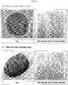
- the filter medium according to the present invention compared to conventional filter media, has excellent heat resistance and heat contraction resistance, and exhibits partial dust collection efficiency of 99% or more by weight, total dust collection efficiency of 99.999% or more by weight, and high dust removal efficiency for all dust particle sizes. Further, pores having an average pore size of 30 ⁇ m or less are and the results of the observation of the surface of the filter media of the present invention by magnifying it 400 times using an electron microscope are shown in FIG. 5 .
- pores formed through foam coating are distributed on the surface of the filter medium of the present invention.
- FIG. 5 it can be seen that a three-dimensional honeycomb structure was also formed in the inner portion of the filter media of the present invention, the same as on the surface thereof.
- Filter media were fabricated by adjusting coating thicknesses in the range of 0.0 ⁇ 0.15 ⁇ at the time of surface coating in the preparation of the filter medium of Example 1. Then, the surface structure of the fabricated filter media, depending on the coating thickness of each filter medium, were observed by magnifying them 100 times using an optical microscope.
- the filter media of the present invention is 0.0 mm
- the filter media is coated in the form of filling the gap between weft and warp, occurring when a glass fiber fabric is woven. Further, it was found that, when the coating thickness was changed by 0.05 ⁇ , no damage to the filter medium, such as rupture of the surface of the filter medium or the like, was observed, and the entire surface of the filter medium was uniformly coated.
- a disk-shaped test piece of the filter medium prepared in Example 1 was marked with a lattice of 5 cm long and 5 cm wide, and was heat-treated in an electric furnace at a temperature of 250°C for 18 hours, and then the change in the shape of the filter medium before and after the heat treatment was observed.
- polyimide P84 which is the commercially available unwoven fabric-type filter medium having the highest heat resistance at high temperatures, was used.
- the filter medium of the present invention was not thermally constricted, and was not carbonized.
- the polyimide P84 was thermally constricted to a great extent, and transformed within 1 minute after it was placed in an electric furnace at 250°C, and the surface thereof became rigid.
- the filter media of the present invention has higher heat resistance than commercially available filter media, and is difficult to thermally constrict compared to the commercially available filter media. Therefore, it is determined that the filter media of the present invention can be successfully applied to the treatment of exhaust gas at medium and high temperatures (250 ⁇ 300°C).
- a filtration performance test device VDI 3926
- the face velocity was changed within the range of 2 ⁇ 10 m/min.
- As comparative filter media a commercially available filter medium laminated with PTFE, m-aramid Nomex, polyphenylsulfide Ryton, Conex, polyimide P84 and a glass fiber were used.
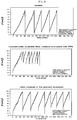
- the filter medium of the present invention has far better differential pressure condition than the commercially available filter medium laminated with PTFE, and has porosity similar to those of various unwoven fabric type filter media which are used at low temperatures. Therefore, it can be seen that the filter medium of the present invention can be applied at low temperatures as well as at medium and high temperatures.
- the filter medium according to the present invention compared to conventional filter media, has excellent heat resistance and heat contraction resistance, and exhibits a partial dust collection efficiency of 99% or more by weight, a total dust collection efficiency of 99.999% or more by weight, and high dust removal efficiency, for all dust particle sizes. Further, the filter medium can be efficiently used to treat medium and high temperature exhaust gas because pores having an average pore size of 30 ⁇ or less are uniformly distributed on the surface of the filter medium.
Landscapes
- Chemical & Material Sciences (AREA)
- Chemical Kinetics & Catalysis (AREA)
- Life Sciences & Earth Sciences (AREA)
- Geology (AREA)
- Filtering Materials (AREA)
Claims (8)
- Verfahren zum Herstellen von einem Filtermedium zum Behandeln von Mittel- und Hochtemperaturabgas, wobei eine Schaumbeschichtung verwendet wird, wobei das Verfahren das Folgende umfasst:1) Mischen von einem hitzebeständigen, wasserlöslichen Harz, einem Schaumstabilisator, einem Schaumbildender und einem Verdickungsmittel in einem Gewichtsverhältnis von 1 : 0,05-0,1 : 0,01-0,02 : 0,01-0,05, um eine Beschichtungslösung herzustellen;2) Behandeln von der Beschichtungslösung, wobei ein Schaumerzeuger verwendet wird, um eine Schaumlösung herzustellen, und dann Auftragen von der Schaumlösung auf eine Oberfläche von einem anorganischen Fasergewebeträger;3) Trocknen des anorganischen Fasergewebeträgers, der mit der Schaumlösung beschichtet ist;4) Pressen des getrockneten, anorganischen Fasergewebeträgers;5) Hitzebehandeln des gepressten, anorganischen Fasergewebeträgers; und6) Kühlen des hitzebehandelten, anorganischen Fasergewebeträgers,wobei das hitzebeständige, wasserlösliche Harz ein Fluoridharz ist, das eine Fluorverbindung umfasst, die durch die untenstehende Formel 1 repräsentiert ist:
<Formel 1> -(CF2CF2)n-
wobei n eine ganze Zahl von 100 bis 10.000 ist. - Verfahren zum Herstellen von einem Filtermedium nach Anspruch 1, wobei der Schaumstabilisator irgendeiner ist, der aus der Gruppe ausgewählt ist, bestehend aus Hydroxyethylcellulose, Carboxymethylcellulose und Ammoniumstearat.
- Verfahren zum Herstellen von einem Filtermedium nach Anspruch 1, wobei der Schaumbildner ein anionischer Schaumbilder, der Natriumlaurat und Natriumstearat umfasst, oder einen nichtionischer Schaumbilder ist, der Polyethylenglycol und minderwertigen Alkohol umfasst.
- Verfahren zum Herstellen von einem Filtermedium nach Anspruch 1, wobei das Verdickungsmittel ein Acrylverdickungsmittel ist.
- Verfahren zum Herstellen von einem Filtermedium nach Anspruch 1, wobei der anorganische Fasergewebeträger eine Glasfaser ist.
- Verfahren zum Herstellen von einem Filtermedium nach Anspruch 1, wobei in dem Schritt 3) der anorganische Fasergewebeträger bei einer Temperatur von 80 °C bis 120 °C getrocknet wird und dann bei einer Temperatur von 180 °C bis 220 °C getrocknet wird.
- Verfahren zum Herstellen von einem Filtermedium nach Anspruch 1, wobei in dem Schritt 4) der getrocknete, anorganische Fasergewebeträger, der mit der Schaumlösung beschichtet ist, bei einem Druck von 1378,95 kPa bis 4826,33 kPa (200 psi bis 700 psi) gepresst wird.
- Verfahren zum Herstellen von einem Filtermedium nach Anspruch 1, wobei in dem Schritt 5) der gepresste, anorganische Fasergewebeträger bei einer Temperatur von 340 °C bis 400 °C hitzebehandelt wird.
Applications Claiming Priority (2)
| Application Number | Priority Date | Filing Date | Title |
|---|---|---|---|
| KR20060136943 | 2006-12-28 | ||
| PCT/KR2007/006978 WO2008082210A1 (en) | 2006-12-28 | 2007-12-28 | Manufacturing method of filter media available at medium and high temperature exhaust gas using foam coating technology and filter media manufactured thereby |
Publications (3)
| Publication Number | Publication Date |
|---|---|
| EP2097153A1 EP2097153A1 (de) | 2009-09-09 |
| EP2097153A4 EP2097153A4 (de) | 2012-06-27 |
| EP2097153B1 true EP2097153B1 (de) | 2017-02-22 |
Family
ID=39588793
Family Applications (1)
| Application Number | Title | Priority Date | Filing Date |
|---|---|---|---|
| EP07860755.3A Active EP2097153B1 (de) | 2006-12-28 | 2007-12-28 | Herstellungsverfahren für filtermedien für mittel- und hochtemperaturabgas über eine schaumstoffbeschichtungstechnologie |
Country Status (6)
| Country | Link |
|---|---|
| US (1) | US8431187B2 (de) |
| EP (1) | EP2097153B1 (de) |
| JP (1) | JP4994446B2 (de) |
| KR (1) | KR100934699B1 (de) |
| CN (1) | CN101479016B (de) |
| WO (1) | WO2008082210A1 (de) |
Families Citing this family (18)
| Publication number | Priority date | Publication date | Assignee | Title |
|---|---|---|---|---|
| CN101927252B (zh) * | 2009-06-22 | 2013-12-04 | 上海佳维特机械设备有限公司 | 液膜抑尘方法 |
| CN101994258B (zh) * | 2009-08-21 | 2014-01-29 | 兴采实业股份有限公司 | 具透气及吸附的多孔性材料纺织品及其制备方法 |
| US20120248034A1 (en) * | 2011-04-01 | 2012-10-04 | Lydall, Inc. | Methods of making and using liquid filter media |
| KR101446586B1 (ko) * | 2012-11-29 | 2014-10-07 | 한국생산기술연구원 | 필터기공크기 조절이 용이한 중ㆍ고온 여과체의 제조방법 |
| KR101433774B1 (ko) * | 2013-10-04 | 2014-08-27 | 한국생산기술연구원 | 3중층으로 구성된 먼지포집용 여과체 |
| CN103961943B (zh) * | 2014-05-09 | 2016-06-22 | 河南龙成煤高效技术应用有限公司 | 一种环绕式喷吹清灰装置 |
| JP6679339B2 (ja) * | 2016-02-18 | 2020-04-15 | ユニチカ株式会社 | 集塵フィルター用布帛 |
| KR101728633B1 (ko) | 2016-03-16 | 2017-05-02 | 박용호 | 정수기용 두루마리형 멀티 필터 제조장치 및 제조방법 |
| KR101728632B1 (ko) | 2016-03-16 | 2017-05-02 | 박용호 | 정수기용 두루마리형 필터 제조장치 및 제조방법 |
| CN106319980A (zh) * | 2016-08-15 | 2017-01-11 | 岚山环保科技(上海)有限公司 | 纺织物抗菌防霉的整理工艺及其应用 |
| CN106422527A (zh) * | 2016-11-29 | 2017-02-22 | 安徽元琛环保科技股份有限公司 | Ptfe发泡涂层整理剂及其涂层复合滤料的制备方法 |
| KR101884321B1 (ko) * | 2018-02-28 | 2018-08-30 | 박용호 | 정수기용 두루마리형 필터 제조장치 및 그 제조방법 |
| KR102541788B1 (ko) | 2019-10-02 | 2023-06-13 | 주식회사 창명산업 | 미세섬유 혼합 거품 코팅을 이용한 산업시설 배가스 처리용 여과체의 제조 방법 및 이에 의해 제조된 여과체 |
| KR102520480B1 (ko) | 2020-08-26 | 2023-04-13 | 한국생산기술연구원 | Ptfe 섬유 여과체 및 그의 제조방법 |
| KR102376501B1 (ko) | 2021-06-22 | 2022-03-18 | 유니온필텍 주식회사 | 미세먼지집진용 복합막 여과체 및 그의 제조방법 |
| CN115591318B (zh) * | 2022-11-14 | 2025-04-25 | 东华大学 | 一种超细纤维发泡涂层针刺复合过滤材料及其制备方法 |
| CN117065460B (zh) * | 2023-08-03 | 2026-04-03 | 中材科技膜材料(山东)有限公司 | 一种发泡溶液及其应用 |
| CN119896912B (zh) * | 2025-03-31 | 2025-07-04 | 浙江东大滤料科技股份有限公司 | 一种复合耐高温过滤毡及其制备方法 |
Citations (1)
| Publication number | Priority date | Publication date | Assignee | Title |
|---|---|---|---|---|
| EP0418285A1 (de) * | 1988-06-04 | 1991-03-27 | Scapa Group Plc | Beschichtete textilien. |
Family Cites Families (28)
| Publication number | Priority date | Publication date | Assignee | Title |
|---|---|---|---|---|
| US3574646A (en) | 1968-03-20 | 1971-04-13 | Ppg Industries Inc | Heat resistant materials |
| US3669823A (en) * | 1969-06-04 | 1972-06-13 | Curlator Corp | Non-woven web |
| US3954662A (en) * | 1972-02-14 | 1976-05-04 | Monsanto Research Corporation | Aqueous foam compositions to suppress coal dust |
| JPS4957069A (de) * | 1972-10-04 | 1974-06-03 | ||
| JPS5044979U (de) * | 1973-08-23 | 1975-05-07 | ||
| IT1134153B (it) * | 1979-11-21 | 1986-07-31 | Siv Soc Italiana Vetro | Ugello per depositare in continuo su un substrato uno strato di una materia solida |
| JPH0246249B2 (ja) * | 1986-06-23 | 1990-10-15 | Ashimori Ind Co Ltd | Fuirutaaoyobisonoseizohoho |
| JP2660419B2 (ja) * | 1988-04-02 | 1997-10-08 | 旭電化工業株式会社 | 安定化された合成樹脂組成物 |
| JPH0212714A (ja) * | 1988-06-30 | 1990-01-17 | Mitsubishi Kasei Corp | コネクター用樹脂被覆基板 |
| US5096616A (en) * | 1989-09-29 | 1992-03-17 | Rusmar Incorporated | Method of providing a foam barrier between a substrate and the atmosphere and compositions therefor |
| US6036735A (en) * | 1998-03-17 | 2000-03-14 | Jps Converter And Industrial Fabrics Corporation | Finish for glass fiber fabric |
| DE19825977C2 (de) * | 1998-06-10 | 2000-04-06 | Kang Dih En Enterprise Co | Plattenfilter und Verfahren zu seiner Herstellung |
| JP3306381B2 (ja) * | 1998-08-27 | 2002-07-24 | 東洋▲ろ▼機製造株式会社 | エアフィルタ |
| KR20000067428A (ko) * | 1999-04-28 | 2000-11-15 | 이충중 | 공기여과용 필터 및 그 제조방법 |
| JP2001240691A (ja) * | 2000-02-28 | 2001-09-04 | Toyo Roki Mfg Co Ltd | 発泡樹脂成形体 |
| KR100367561B1 (ko) * | 2000-06-15 | 2003-01-10 | 크린에어테크놀로지 주식회사 | 미세기공코팅 유리섬유 직포필터 및 그의 제조방법 |
| KR100358651B1 (ko) | 2000-06-27 | 2002-10-31 | (주)대보휄트 | 에어필터의 여과지 및 그의 제조방법 |
| KR20020022343A (ko) | 2000-09-20 | 2002-03-27 | 홍민선 | 세라믹 섬유를 이용한 디젤 입자상물질 여과장치 |
| US20030084788A1 (en) | 2001-06-22 | 2003-05-08 | Fraser Ladson L | Foam coated air filtration media |
| GB0120094D0 (en) * | 2001-08-17 | 2001-10-10 | Madison Filter 981 Ltd | Heat stable filter construction |
| TWI296538B (en) * | 2001-12-28 | 2008-05-11 | Chao-Ming Wang | A foam filter and the manufacturing method thereof |
| JP4042045B2 (ja) | 2002-02-08 | 2008-02-06 | 株式会社デンソー | 内燃機関用点火コイル |
| KR100450983B1 (ko) * | 2002-03-12 | 2004-10-02 | 크린에어테크놀로지 주식회사 | 통기성이 우수한 코팅 직포필터의 제조방법 |
| KR100463921B1 (ko) | 2002-03-19 | 2004-12-30 | 박경순 | 알루미나계 주물용 세라믹 필터 및 그 제조방법 |
| DE10247241A1 (de) * | 2002-10-10 | 2004-04-22 | Basf Ag | Superabsorbierender Schaum, Verfahren zu seiner Herstellung und seine Verwendung |
| KR100690573B1 (ko) | 2002-12-05 | 2007-03-09 | 주식회사 이비에스아이 | 세라믹 필터 및 그 제조방법 |
| KR100658177B1 (ko) | 2004-04-12 | 2006-12-14 | 이노필텍(주) | 집진기용 내열 필터여재 및 그 제조방법 |
| KR100816094B1 (ko) | 2004-06-17 | 2008-03-24 | 주식회사 크리에이티브테크놀로지 | 삼차원 수지 기공을 내포하는 여재 및 그 제조방법 |
-
2007
- 2007-12-28 EP EP07860755.3A patent/EP2097153B1/de active Active
- 2007-12-28 JP JP2009516414A patent/JP4994446B2/ja active Active
- 2007-12-28 KR KR1020070140294A patent/KR100934699B1/ko active Active
- 2007-12-28 WO PCT/KR2007/006978 patent/WO2008082210A1/en not_active Ceased
- 2007-12-28 US US12/306,212 patent/US8431187B2/en active Active
- 2007-12-28 CN CN2007800243158A patent/CN101479016B/zh active Active
Patent Citations (1)
| Publication number | Priority date | Publication date | Assignee | Title |
|---|---|---|---|---|
| EP0418285A1 (de) * | 1988-06-04 | 1991-03-27 | Scapa Group Plc | Beschichtete textilien. |
Also Published As
| Publication number | Publication date |
|---|---|
| EP2097153A4 (de) | 2012-06-27 |
| JP4994446B2 (ja) | 2012-08-08 |
| KR100934699B1 (ko) | 2009-12-30 |
| WO2008082210A1 (en) | 2008-07-10 |
| CN101479016B (zh) | 2011-09-21 |
| EP2097153A1 (de) | 2009-09-09 |
| CN101479016A (zh) | 2009-07-08 |
| US20090199528A1 (en) | 2009-08-13 |
| US8431187B2 (en) | 2013-04-30 |
| KR20080063193A (ko) | 2008-07-03 |
| JP2009541029A (ja) | 2009-11-26 |
Similar Documents
| Publication | Publication Date | Title |
|---|---|---|
| US8431187B2 (en) | Manufacturing method of filter media available at medium and high temperature exhaust gas using foam coating technology and filter media manufactured thereby | |
| RU2163228C2 (ru) | Способ химической инфильтрации из паровой фазы с переменными параметрами инфильтрации | |
| KR20040049279A (ko) | 다층 세라믹 필터의 제조방법 및 이를 이용한 세라믹 필터 | |
| CA2288989A1 (en) | High performance filters | |
| KR102065049B1 (ko) | 내열성 고분자 섬유의 다공성 네트워크를 포함하는 중ㆍ고온 배가스의 먼지포집용 여과체 및 그의 제조방법 | |
| KR100294857B1 (ko) | 미세분진여과용집진필터및그제조방법 | |
| Gao et al. | Emerging fabrication of ceramic nanofiber aerogel with the application in high-temperature thermal insulation, environment, and electromagnetic wave absorption | |
| US9796632B2 (en) | Method for manufacturing ceramic filter | |
| EP2832414B1 (de) | Herstellungsverfahren für einen wabenfilter | |
| JP2002346321A (ja) | 浄水フィルター | |
| KR100623362B1 (ko) | 금속 세라믹 필터 및 그 제조방법 | |
| JP6039820B2 (ja) | セラミックフィルタの製造方法 | |
| KR20230091174A (ko) | 탄화규소질 세라믹 허니컴 구조체 및 그 제조 방법 | |
| KR101041505B1 (ko) | 적층형 세라믹 필터의 제조방법 및 이에 의해 제조되는적층형 세라믹 필터 | |
| Krasnyi et al. | Porous permeable ceramics for filter elements cleaning hot gases from dust | |
| KR100673141B1 (ko) | 거품 코팅을 이용한 중ㆍ고온용 여과체 제조 방법 및 이방법에 의해 제조된 여과체 | |
| JP3872096B1 (ja) | オイルミストフィルター | |
| KR100761635B1 (ko) | 거품코팅을 이용한 중·고온 배가스 처리용 여과체의제조방법 및 이에 의해 제조된 여과체 | |
| KR100367561B1 (ko) | 미세기공코팅 유리섬유 직포필터 및 그의 제조방법 | |
| Ohzawa et al. | Preparation of gas-permeable SiC shape by pressure-pulsed chemical vapour infiltration into carbonized cotton-cloth preforms | |
| KR102517386B1 (ko) | 초정밀 여과층을 구비한 세라믹 필터 제조 장치 및 방법 | |
| KR102621800B1 (ko) | 나노 섬유 필터 및 그 제조 방법 | |
| CN111039659A (zh) | 一种耐高温过滤材料的制备方法 | |
| CN220573155U (zh) | 一种具有梯度结构的聚四氟乙烯复合膜 | |
| KR101694250B1 (ko) | 비드소재의 코팅 소결방법을 이용한 여과체 제조방법 및 그에 따른 여과체 |
Legal Events
| Date | Code | Title | Description |
|---|---|---|---|
| PUAI | Public reference made under article 153(3) epc to a published international application that has entered the european phase |
Free format text: ORIGINAL CODE: 0009012 |
|
| 17P | Request for examination filed |
Effective date: 20081219 |
|
| AK | Designated contracting states |
Kind code of ref document: A1 Designated state(s): AT BE BG CH CY CZ DE DK EE ES FI FR GB GR HU IE IS IT LI LT LU LV MC MT NL PL PT RO SE SI SK TR |
|
| DAX | Request for extension of the european patent (deleted) | ||
| A4 | Supplementary search report drawn up and despatched |
Effective date: 20120530 |
|
| RIC1 | Information provided on ipc code assigned before grant |
Ipc: B01D 46/00 20060101ALI20120523BHEP Ipc: B01D 39/20 20060101ALI20120523BHEP Ipc: B01D 39/00 20060101AFI20120523BHEP |
|
| 17Q | First examination report despatched |
Effective date: 20160222 |
|
| REG | Reference to a national code |
Ref country code: DE Ref legal event code: R079 Ref document number: 602007049907 Country of ref document: DE Free format text: PREVIOUS MAIN CLASS: B01D0039000000 Ipc: B01D0039180000 |
|
| GRAP | Despatch of communication of intention to grant a patent |
Free format text: ORIGINAL CODE: EPIDOSNIGR1 |
|
| STAA | Information on the status of an ep patent application or granted ep patent |
Free format text: STATUS: GRANT OF PATENT IS INTENDED |
|
| RIC1 | Information provided on ipc code assigned before grant |
Ipc: B01D 39/18 20060101AFI20161006BHEP Ipc: B01D 39/20 20060101ALI20161006BHEP Ipc: B01D 46/00 20060101ALI20161006BHEP |
|
| INTG | Intention to grant announced |
Effective date: 20161103 |
|
| GRAS | Grant fee paid |
Free format text: ORIGINAL CODE: EPIDOSNIGR3 |
|
| GRAA | (expected) grant |
Free format text: ORIGINAL CODE: 0009210 |
|
| STAA | Information on the status of an ep patent application or granted ep patent |
Free format text: STATUS: THE PATENT HAS BEEN GRANTED |
|
| AK | Designated contracting states |
Kind code of ref document: B1 Designated state(s): AT BE BG CH CY CZ DE DK EE ES FI FR GB GR HU IE IS IT LI LT LU LV MC MT NL PL PT RO SE SI SK TR |
|
| REG | Reference to a national code |
Ref country code: GB Ref legal event code: FG4D |
|
| REG | Reference to a national code |
Ref country code: CH Ref legal event code: EP |
|
| REG | Reference to a national code |
Ref country code: AT Ref legal event code: REF Ref document number: 868814 Country of ref document: AT Kind code of ref document: T Effective date: 20170315 |
|
| REG | Reference to a national code |
Ref country code: IE Ref legal event code: FG4D |
|
| REG | Reference to a national code |
Ref country code: DE Ref legal event code: R096 Ref document number: 602007049907 Country of ref document: DE |
|
| REG | Reference to a national code |
Ref country code: LT Ref legal event code: MG4D |
|
| REG | Reference to a national code |
Ref country code: NL Ref legal event code: MP Effective date: 20170222 |
|
| REG | Reference to a national code |
Ref country code: AT Ref legal event code: MK05 Ref document number: 868814 Country of ref document: AT Kind code of ref document: T Effective date: 20170222 |
|
| PG25 | Lapsed in a contracting state [announced via postgrant information from national office to epo] |
Ref country code: GR Free format text: LAPSE BECAUSE OF FAILURE TO SUBMIT A TRANSLATION OF THE DESCRIPTION OR TO PAY THE FEE WITHIN THE PRESCRIBED TIME-LIMIT Effective date: 20170523 Ref country code: FI Free format text: LAPSE BECAUSE OF FAILURE TO SUBMIT A TRANSLATION OF THE DESCRIPTION OR TO PAY THE FEE WITHIN THE PRESCRIBED TIME-LIMIT Effective date: 20170222 Ref country code: LT Free format text: LAPSE BECAUSE OF FAILURE TO SUBMIT A TRANSLATION OF THE DESCRIPTION OR TO PAY THE FEE WITHIN THE PRESCRIBED TIME-LIMIT Effective date: 20170222 |
|
| PG25 | Lapsed in a contracting state [announced via postgrant information from national office to epo] |
Ref country code: SE Free format text: LAPSE BECAUSE OF FAILURE TO SUBMIT A TRANSLATION OF THE DESCRIPTION OR TO PAY THE FEE WITHIN THE PRESCRIBED TIME-LIMIT Effective date: 20170222 Ref country code: ES Free format text: LAPSE BECAUSE OF FAILURE TO SUBMIT A TRANSLATION OF THE DESCRIPTION OR TO PAY THE FEE WITHIN THE PRESCRIBED TIME-LIMIT Effective date: 20170222 Ref country code: NL Free format text: LAPSE BECAUSE OF FAILURE TO SUBMIT A TRANSLATION OF THE DESCRIPTION OR TO PAY THE FEE WITHIN THE PRESCRIBED TIME-LIMIT Effective date: 20170222 Ref country code: PT Free format text: LAPSE BECAUSE OF FAILURE TO SUBMIT A TRANSLATION OF THE DESCRIPTION OR TO PAY THE FEE WITHIN THE PRESCRIBED TIME-LIMIT Effective date: 20170622 Ref country code: LV Free format text: LAPSE BECAUSE OF FAILURE TO SUBMIT A TRANSLATION OF THE DESCRIPTION OR TO PAY THE FEE WITHIN THE PRESCRIBED TIME-LIMIT Effective date: 20170222 Ref country code: BG Free format text: LAPSE BECAUSE OF FAILURE TO SUBMIT A TRANSLATION OF THE DESCRIPTION OR TO PAY THE FEE WITHIN THE PRESCRIBED TIME-LIMIT Effective date: 20170522 Ref country code: AT Free format text: LAPSE BECAUSE OF FAILURE TO SUBMIT A TRANSLATION OF THE DESCRIPTION OR TO PAY THE FEE WITHIN THE PRESCRIBED TIME-LIMIT Effective date: 20170222 |
|
| PG25 | Lapsed in a contracting state [announced via postgrant information from national office to epo] |
Ref country code: CZ Free format text: LAPSE BECAUSE OF FAILURE TO SUBMIT A TRANSLATION OF THE DESCRIPTION OR TO PAY THE FEE WITHIN THE PRESCRIBED TIME-LIMIT Effective date: 20170222 Ref country code: EE Free format text: LAPSE BECAUSE OF FAILURE TO SUBMIT A TRANSLATION OF THE DESCRIPTION OR TO PAY THE FEE WITHIN THE PRESCRIBED TIME-LIMIT Effective date: 20170222 Ref country code: IT Free format text: LAPSE BECAUSE OF FAILURE TO SUBMIT A TRANSLATION OF THE DESCRIPTION OR TO PAY THE FEE WITHIN THE PRESCRIBED TIME-LIMIT Effective date: 20170222 Ref country code: SK Free format text: LAPSE BECAUSE OF FAILURE TO SUBMIT A TRANSLATION OF THE DESCRIPTION OR TO PAY THE FEE WITHIN THE PRESCRIBED TIME-LIMIT Effective date: 20170222 Ref country code: RO Free format text: LAPSE BECAUSE OF FAILURE TO SUBMIT A TRANSLATION OF THE DESCRIPTION OR TO PAY THE FEE WITHIN THE PRESCRIBED TIME-LIMIT Effective date: 20170222 |
|
| REG | Reference to a national code |
Ref country code: DE Ref legal event code: R097 Ref document number: 602007049907 Country of ref document: DE |
|
| PG25 | Lapsed in a contracting state [announced via postgrant information from national office to epo] |
Ref country code: DK Free format text: LAPSE BECAUSE OF FAILURE TO SUBMIT A TRANSLATION OF THE DESCRIPTION OR TO PAY THE FEE WITHIN THE PRESCRIBED TIME-LIMIT Effective date: 20170222 Ref country code: PL Free format text: LAPSE BECAUSE OF FAILURE TO SUBMIT A TRANSLATION OF THE DESCRIPTION OR TO PAY THE FEE WITHIN THE PRESCRIBED TIME-LIMIT Effective date: 20170222 |
|
| PLBE | No opposition filed within time limit |
Free format text: ORIGINAL CODE: 0009261 |
|
| STAA | Information on the status of an ep patent application or granted ep patent |
Free format text: STATUS: NO OPPOSITION FILED WITHIN TIME LIMIT |
|
| 26N | No opposition filed |
Effective date: 20171123 |
|
| PG25 | Lapsed in a contracting state [announced via postgrant information from national office to epo] |
Ref country code: SI Free format text: LAPSE BECAUSE OF FAILURE TO SUBMIT A TRANSLATION OF THE DESCRIPTION OR TO PAY THE FEE WITHIN THE PRESCRIBED TIME-LIMIT Effective date: 20170222 |
|
| REG | Reference to a national code |
Ref country code: CH Ref legal event code: PL |
|
| REG | Reference to a national code |
Ref country code: IE Ref legal event code: MM4A |
|
| PG25 | Lapsed in a contracting state [announced via postgrant information from national office to epo] |
Ref country code: LU Free format text: LAPSE BECAUSE OF NON-PAYMENT OF DUE FEES Effective date: 20171228 Ref country code: MT Free format text: LAPSE BECAUSE OF NON-PAYMENT OF DUE FEES Effective date: 20171228 |
|
| REG | Reference to a national code |
Ref country code: FR Ref legal event code: ST Effective date: 20180831 |
|
| REG | Reference to a national code |
Ref country code: BE Ref legal event code: MM Effective date: 20171231 |
|
| PG25 | Lapsed in a contracting state [announced via postgrant information from national office to epo] |
Ref country code: FR Free format text: LAPSE BECAUSE OF NON-PAYMENT OF DUE FEES Effective date: 20180102 Ref country code: IE Free format text: LAPSE BECAUSE OF NON-PAYMENT OF DUE FEES Effective date: 20171228 |
|
| PG25 | Lapsed in a contracting state [announced via postgrant information from national office to epo] |
Ref country code: BE Free format text: LAPSE BECAUSE OF NON-PAYMENT OF DUE FEES Effective date: 20171231 Ref country code: CH Free format text: LAPSE BECAUSE OF NON-PAYMENT OF DUE FEES Effective date: 20171231 Ref country code: LI Free format text: LAPSE BECAUSE OF NON-PAYMENT OF DUE FEES Effective date: 20171231 |
|
| PG25 | Lapsed in a contracting state [announced via postgrant information from national office to epo] |
Ref country code: HU Free format text: LAPSE BECAUSE OF FAILURE TO SUBMIT A TRANSLATION OF THE DESCRIPTION OR TO PAY THE FEE WITHIN THE PRESCRIBED TIME-LIMIT; INVALID AB INITIO Effective date: 20071228 Ref country code: MC Free format text: LAPSE BECAUSE OF FAILURE TO SUBMIT A TRANSLATION OF THE DESCRIPTION OR TO PAY THE FEE WITHIN THE PRESCRIBED TIME-LIMIT Effective date: 20170222 |
|
| PG25 | Lapsed in a contracting state [announced via postgrant information from national office to epo] |
Ref country code: CY Free format text: LAPSE BECAUSE OF NON-PAYMENT OF DUE FEES Effective date: 20170222 |
|
| PG25 | Lapsed in a contracting state [announced via postgrant information from national office to epo] |
Ref country code: TR Free format text: LAPSE BECAUSE OF FAILURE TO SUBMIT A TRANSLATION OF THE DESCRIPTION OR TO PAY THE FEE WITHIN THE PRESCRIBED TIME-LIMIT Effective date: 20170222 |
|
| PG25 | Lapsed in a contracting state [announced via postgrant information from national office to epo] |
Ref country code: IS Free format text: LAPSE BECAUSE OF FAILURE TO SUBMIT A TRANSLATION OF THE DESCRIPTION OR TO PAY THE FEE WITHIN THE PRESCRIBED TIME-LIMIT Effective date: 20170622 |
|
| PGFP | Annual fee paid to national office [announced via postgrant information from national office to epo] |
Ref country code: DE Payment date: 20250922 Year of fee payment: 19 |
|
| PGFP | Annual fee paid to national office [announced via postgrant information from national office to epo] |
Ref country code: GB Payment date: 20251001 Year of fee payment: 19 |