EP2099384B1 - Dispositif d'insertion et procédé pour insérer un élément insérable de manière sous-cutanée à l'intérieur d'un corps - Google Patents
Dispositif d'insertion et procédé pour insérer un élément insérable de manière sous-cutanée à l'intérieur d'un corps Download PDFInfo
- Publication number
- EP2099384B1 EP2099384B1 EP07827427.1A EP07827427A EP2099384B1 EP 2099384 B1 EP2099384 B1 EP 2099384B1 EP 07827427 A EP07827427 A EP 07827427A EP 2099384 B1 EP2099384 B1 EP 2099384B1
- Authority
- EP
- European Patent Office
- Prior art keywords
- penetrating
- inserter
- well
- cartridge
- cannula
- Prior art date
- Legal status (The legal status is an assumption and is not a legal conclusion. Google has not performed a legal analysis and makes no representation as to the accuracy of the status listed.)
- Active
Links
Images







Classifications
-
- A—HUMAN NECESSITIES
- A61—MEDICAL OR VETERINARY SCIENCE; HYGIENE
- A61B—DIAGNOSIS; SURGERY; IDENTIFICATION
- A61B5/00—Measuring for diagnostic purposes; Identification of persons
- A61B5/145—Measuring characteristics of blood in vivo, e.g. gas concentration or pH-value ; Measuring characteristics of body fluids or tissues, e.g. interstitial fluid or cerebral tissue
- A61B5/14503—Measuring characteristics of blood in vivo, e.g. gas concentration or pH-value ; Measuring characteristics of body fluids or tissues, e.g. interstitial fluid or cerebral tissue invasive, e.g. introduced into the body by a catheter or needle or using implanted sensors
-
- A—HUMAN NECESSITIES
- A61—MEDICAL OR VETERINARY SCIENCE; HYGIENE
- A61B—DIAGNOSIS; SURGERY; IDENTIFICATION
- A61B5/00—Measuring for diagnostic purposes; Identification of persons
- A61B5/145—Measuring characteristics of blood in vivo, e.g. gas concentration or pH-value ; Measuring characteristics of body fluids or tissues, e.g. interstitial fluid or cerebral tissue
- A61B5/14532—Measuring characteristics of blood in vivo, e.g. gas concentration or pH-value ; Measuring characteristics of body fluids or tissues, e.g. interstitial fluid or cerebral tissue for measuring glucose, e.g. by tissue impedance measurement
-
- A—HUMAN NECESSITIES
- A61—MEDICAL OR VETERINARY SCIENCE; HYGIENE
- A61B—DIAGNOSIS; SURGERY; IDENTIFICATION
- A61B5/00—Measuring for diagnostic purposes; Identification of persons
- A61B5/68—Arrangements of detecting, measuring or recording means, e.g. sensors, in relation to patient
- A61B5/6846—Arrangements of detecting, measuring or recording means, e.g. sensors, in relation to patient specially adapted to be brought in contact with an internal body part, i.e. invasive
- A61B5/6847—Arrangements of detecting, measuring or recording means, e.g. sensors, in relation to patient specially adapted to be brought in contact with an internal body part, i.e. invasive mounted on an invasive device
- A61B5/6848—Needles
-
- A—HUMAN NECESSITIES
- A61—MEDICAL OR VETERINARY SCIENCE; HYGIENE
- A61M—DEVICES FOR INTRODUCING MEDIA INTO, OR ONTO, THE BODY; DEVICES FOR TRANSDUCING BODY MEDIA OR FOR TAKING MEDIA FROM THE BODY; DEVICES FOR PRODUCING OR ENDING SLEEP OR STUPOR
- A61M5/00—Devices for bringing media into the body in a subcutaneous, intra-vascular or intramuscular way; Accessories therefor, e.g. filling or cleaning devices, arm-rests
- A61M5/14—Infusion devices, e.g. infusing by gravity; Blood infusion; Accessories therefor
- A61M5/158—Needles for infusions; Accessories therefor, e.g. for inserting infusion needles, or for holding them on the body
-
- A—HUMAN NECESSITIES
- A61—MEDICAL OR VETERINARY SCIENCE; HYGIENE
- A61B—DIAGNOSIS; SURGERY; IDENTIFICATION
- A61B5/00—Measuring for diagnostic purposes; Identification of persons
- A61B5/15—Devices for taking samples of blood
- A61B5/150007—Details
- A61B5/150015—Source of blood
- A61B5/150022—Source of blood for capillary blood or interstitial fluid
-
- A—HUMAN NECESSITIES
- A61—MEDICAL OR VETERINARY SCIENCE; HYGIENE
- A61M—DEVICES FOR INTRODUCING MEDIA INTO, OR ONTO, THE BODY; DEVICES FOR TRANSDUCING BODY MEDIA OR FOR TAKING MEDIA FROM THE BODY; DEVICES FOR PRODUCING OR ENDING SLEEP OR STUPOR
- A61M5/00—Devices for bringing media into the body in a subcutaneous, intra-vascular or intramuscular way; Accessories therefor, e.g. filling or cleaning devices, arm-rests
- A61M5/002—Packages specially adapted therefor, e.g. for syringes or needles, kits for diabetics
- A61M2005/004—Magazines with multiple needles directly inserted into an injection or infusion device, e.g. revolver-like magazines
-
- A—HUMAN NECESSITIES
- A61—MEDICAL OR VETERINARY SCIENCE; HYGIENE
- A61M—DEVICES FOR INTRODUCING MEDIA INTO, OR ONTO, THE BODY; DEVICES FOR TRANSDUCING BODY MEDIA OR FOR TAKING MEDIA FROM THE BODY; DEVICES FOR PRODUCING OR ENDING SLEEP OR STUPOR
- A61M5/00—Devices for bringing media into the body in a subcutaneous, intra-vascular or intramuscular way; Accessories therefor, e.g. filling or cleaning devices, arm-rests
- A61M5/14—Infusion devices, e.g. infusing by gravity; Blood infusion; Accessories therefor
- A61M5/158—Needles for infusions; Accessories therefor, e.g. for inserting infusion needles, or for holding them on the body
- A61M2005/1581—Right-angle needle-type devices
-
- A—HUMAN NECESSITIES
- A61—MEDICAL OR VETERINARY SCIENCE; HYGIENE
- A61M—DEVICES FOR INTRODUCING MEDIA INTO, OR ONTO, THE BODY; DEVICES FOR TRANSDUCING BODY MEDIA OR FOR TAKING MEDIA FROM THE BODY; DEVICES FOR PRODUCING OR ENDING SLEEP OR STUPOR
- A61M5/00—Devices for bringing media into the body in a subcutaneous, intra-vascular or intramuscular way; Accessories therefor, e.g. filling or cleaning devices, arm-rests
- A61M5/14—Infusion devices, e.g. infusing by gravity; Blood infusion; Accessories therefor
- A61M5/158—Needles for infusions; Accessories therefor, e.g. for inserting infusion needles, or for holding them on the body
- A61M2005/1585—Needle inserters
-
- A—HUMAN NECESSITIES
- A61—MEDICAL OR VETERINARY SCIENCE; HYGIENE
- A61M—DEVICES FOR INTRODUCING MEDIA INTO, OR ONTO, THE BODY; DEVICES FOR TRANSDUCING BODY MEDIA OR FOR TAKING MEDIA FROM THE BODY; DEVICES FOR PRODUCING OR ENDING SLEEP OR STUPOR
- A61M5/00—Devices for bringing media into the body in a subcutaneous, intra-vascular or intramuscular way; Accessories therefor, e.g. filling or cleaning devices, arm-rests
- A61M5/178—Syringes
- A61M5/20—Automatic syringes, e.g. with automatically actuated piston rod, with automatic needle injection, filling automatically
- A61M2005/2073—Automatic syringes, e.g. with automatically actuated piston rod, with automatic needle injection, filling automatically preventing premature release, e.g. by making use of a safety lock
-
- A—HUMAN NECESSITIES
- A61—MEDICAL OR VETERINARY SCIENCE; HYGIENE
- A61M—DEVICES FOR INTRODUCING MEDIA INTO, OR ONTO, THE BODY; DEVICES FOR TRANSDUCING BODY MEDIA OR FOR TAKING MEDIA FROM THE BODY; DEVICES FOR PRODUCING OR ENDING SLEEP OR STUPOR
- A61M5/00—Devices for bringing media into the body in a subcutaneous, intra-vascular or intramuscular way; Accessories therefor, e.g. filling or cleaning devices, arm-rests
- A61M5/178—Syringes
- A61M5/31—Details
- A61M5/32—Needles; Details of needles pertaining to their connection with syringe or hub; Accessories for bringing the needle into, or holding the needle on, the body; Devices for protection of needles
- A61M5/3287—Accessories for bringing the needle into the body; Automatic needle insertion
Definitions
- This invention relates to medical devices, and more particularly to a device, which assists in insertion of a cannula, which is suitable for subcutaneous administering of a medication into the skin of a patient and/or for sensing analyte levels in a body fluid. Even more particularly, the present invention is directed to an insertion device for manual or automatic insertion of a cannula for delivery of a drug supplied by an infusion pump and/or for continuous sensing of a subcutaneous body analyte.
- Continuous subcutaneous delivery of medication or monitoring of a body analyte is often accomplished through the use of a cannula, which should remain in place for several days.
- Diabetes patients may use such a cannula as a subcutaneous compartment for continuous delivery of insulin by pumps or for monitoring interstitial glucose levels by sensors.
- a combination of a tube, connecting the insulin pump to the cannula and a detachable connector is often referred to as an infusion set.
- Such infusion sets and modes of their insertion are disclosed, for example, in U.S. Patents Nos. 4,755,173 , 5,176,662 and 5,257,980 .
- Subcutaneous cannula insertion modes for continuous glucose monitoring are disclosed for example in U.S. Patents Nos.
- transcutaneous cannula insertion can be carried out with a sharp metal penetrating member to be withdrawn after skin pricking. This procedure can be effected manually by the patient.
- the insertion is usually painful and requires considerable skill. Some patients are reluctant or hesitant to pierce their own skin, and thus encounter difficulties in proper cannula insertion. Such difficulties can be attributable to insufficient manual dexterity or alternately to anxiety associated with anticipated discomfort as the needle pierces the skin.
- This problem can be especially significant when an insulin pump is used since misplacement of the cannula can cause kinking, incorrect insertion angle or incorrect cannula insertion depth leading eventually to cannula obstruction. As a result of this, delivery of insulin may be life threatening.
- US 2004/158207 A1 discloses an infusion set which uses a base member to be placed on a desired injection site.
- U.S. Patents Nos. 6,093,172 and 6,830,562 disclose injector devices comprising a spring-loaded plunger for an automatic subcutaneous placement of an infusion set.
- An automatic cannula insertion is also employed in the skin adhered insulin pump disclosed in U.S. Patent No. 6,699,218 assigned to Flaherty et al.
- this device is relatively bulky, heavy and indiscreet because the spring loaded mechanism is enclosed within the housing during the entire period of usage.
- a skin adherable insulin delivery device was disclosed in co-owned U.S. Provisional Patent Application No. 60/837,877 .
- This device includes a unique apparatus for cannula insertion, which does not require an infusion set and long tubing.
- the cannula insertion apparatus allows the patient to choose the desired depth for cannula insertion and the desired insertion angle.
- the device is provided with a "well -assembly" connected to the insulin delivery tube.
- the well assembly has an upper opening and a lower rubber gasket.
- the insertion apparatus is provided also with a "penetrating cartridge" having a cannula, a penetrating member and a rubber cap. The penetrating cartridge allows for the cannula to penetrate through the well assembly and then through skin, while sealing the upper opening and maintaining the delivery of insulin.
- a cannula inserter that can be precisely aligned with the well and subsequently allows pivoting of the well to a desired penetration angle.
- the inserter itself may serve as a rotating handle which increases the moment applied to the well, thus preventing direct contact between the user's hands and the delicate, sterile, miniature well.
- the device for cannula insertion will be referred to as a cannula inserter or simply as an inserter.
- the patch type fluid delivery pump will be referred to as the patch.
- Some of the embodiments of the present invention are directed to an inserter for precise placement of a subcutaneously insertable element, i.e. a cannula or a sensor within a user's subcutaneous tissue.
- the device is intended for automatic or manual insertion of the insertable element through a fluid delivery pump.
- the pump may be a patch type pump adherable to the user's body and suitable for controllable fluid delivery or continuous analyte level monitoring.
- delivering of the therapeutic fluid via a cannula will be mentioned, this should not be understood as limiting the present invention to inserting of merely a cannula.
- the present invention refers equally to an insertion device capable of inserting any other subcutanelsly insertable elements, e.g. a sensor for sensing of a bodily analyte.
- the delivered fluid is insulin and the monitored analyte is glucose.
- the skin adhered patch pump contains a fluid reservoir, a well and a delivery tube through which the fluid is delivered from the reservoir to the well.
- the well includes an opening arranged within the patch pump housing. The well allows fluid dripping during priming (purging the air out of the reservoir and out of the delivery tube). The well also maintains fluid communication between the delivery tube and the user's body after cannula insertion.
- the well has an upper side opening and a self-sealing rubber septum on its lower side. The inserter allows automatic insertion of a penetrating cartridge into the tissue and either manual or automatic retraction of the penetrating member from the tissue.
- the penetrating cartridge has a subcutanelusly insertable element, a penetrating member provided with a grip portion and a well sealing cap.
- the penetrating cartridge is contained within the inserter and is fired by a spring loaded mechanism, activated by the user.
- the penetrating member and the subcutanelusly insertable element pierce the septum at the well's lower side and then pierce the skin, and penetrate the subcutaneous region.
- the well sealing cap seals the opening at the well's upper side.
- the penetrating member is retracted back outside of the skin and outside the well, either manually or automatically.
- an insertion device for use in a device for delivery of a therapeutic fluid to a body of a patient and/or for sensing an analyte.
- the insertion device is provided with a housing loadable by at least one penetrating cartridge consisting of a subcutaneously insertable element and a penetrating member for penetrating the subcutaneous tissue and delivering the subcutaneously insertable element to the subcutaneous tissue.
- the housing also includes a trigger coupled to the penetrating cartridge to actuate insertion of the penetrating member along with the subcutaneously insertable element into the subcutaneous tissue, while the insertion takes place via the device for delivery of the therapeutic fluid and/or for sensing a bodily analyte.
- the insertion can take place only when the penetrating cartridge is located at a predetermined position with respect to the subcutaneous tissue.
- the insertion device is provided with a safety means, which prevents accidental insertion of the penetrating member and the subcutaneously insertable member.
- the insertion device is provided with a retracting mechanism enabling automatic retraction of the penetrating member from the subcutaneous tissue.
- the subcutaneously insertable element is a cannula for delivering a therapeutic fluid.
- the subcutaneously insertable element is a sensor for sensing a bodily analyte.
- a method for delivering therapeutic fluid to a body of a patient and /or for sensing of a bodily analyte includes providing a device for delivering of a therapeutic fluid to a body of a patient and/or for sensing of a bodily analyte, while said device being provided with an insertion device according to the above noted embodiment.
- the insertion device is loadable by at least one penetrating cartridge having a subcutaneously insertable element and a penetrating member.
- the method further comprises inserting the penetrating member and the subcutaneously insertable element into the subcutaneous tissue, removing the penetrating member from the tissue, while allowing the subcutaneously insertable element to remain in the subcutaneous tissue.
- the method further comprises delivering therapeutic fluid to the body of the patient and/or sensing of bodily analyte through the subcutaneously insertable element.
- the insertion device is provided with a spring loaded actuator for initiation of insertion the penetrating member and the subcutaneously insertable element to the subcutaneous tissue and removal of the penetrating member from the subcutaneous tissue after the subcutanelusly insertable element is inserted into the subcutaneous tissue.
- the insertion device comprises a safety means for enabling insertion of the penetrating member only when the insertion device is placed in a predetermined position with respect to the,device for delivery and/or for sensing
- the safety means includes a safety rod configured to be positioned at a predetermined location to enable discharge of the penetrating member, a trigger for initiating discharge of the penetrating member into the subcutaneous tissue and a retractor for retracting the penetrating member after insertion and for retaining the cannula inside the subcutaneous tissue, where the retracting of the penetrating member is configured to be automatic.
- a method for inserting a subcutaneously insertable element within a subcutaneous tissue of a patient using an insertion device includes inserting the penetrating member and the subcutaneously insertable element into the body and removing the penetrating member by gripping the grip portion thereof while retaining the subcutaneously insertable element in the body and further retaining the well sealing cap at an upper opening of the well.
- disoposable inserter is preloaded with a penetrating cartridge and after insertion the used penetrating member is retracted and remains within the inserter housing, which is then discarded together with the inserter.
- the used penetrating member remains attached to the pump housing and should be manually removed therefrom.
- the safety means could be integrated within the inserter or may be an additional component that is attachable to the inserter, and detachable before operation.
- the invention is defined by the subject-matter of claim 1.
- the inserter is intended to insert a cannula into the user's body, for the purposes of delivering fluids.
- the cannula which can be made from a soft material, can penetrate the skin by means of a penetrating member (a guide needle) which is retracted after insertion.
- a fluid delivery device for example configured as a patch, adherable to the user's body, contains the fluid to be delivered.
- the cannula is inserted in the subcutaneous compartment of a body of a patient through a designated location on the patch, i.e. through a "well".
- the inserter which is provided with a trigger, is placed on the patch above the well.
- the penetrating member After the trigger is fired the cannula and the penetrating member protracts and penetrates through the well into the skin, the penetrating member is then retracted from the subcutaneous compartment while the cannula remains thereinto and thus fluid communication is allowed between the fluid reservoir and the user's body via the cannula.
- the inserter includes the following features:
- FIG 1 shows a general view of one of the embodiments of the present invention.
- An inserter (100) is ready to perform the insertion of a cannula along with a penetrating member into the user's body (4).
- the cannula is inserted through a well (107) that is provided at a patch type delivery pump (105).
- the patch is adherable to a patient's skin (5).
- the inserter (100) is operated by a trigger button (330), which is activated by the patient.
- insertion can be accomplished when the inserter is deployed substantially perpendicular to the skin. This will be referred to as a perpendicular mode (90° penetration angle and/or thereabout).
- the inserter can be gripped by hand and pivoted together with the well such that desired penetration angle can be chosen and cannula insertion can be carried out at that chosen penetrating angle.
- the inserter includes a penetrating cartridge, which is fired by the inserter into the skin.
- a penetrating cartridge is shown in Figure 2 and includes the following parts:
- the insertion process is associated with the following steps:
- Figure 2 shows the penetrating cartridge (150) according to some embodiments, which comprises a penetrating member (111), having a sharp end and an opposite blunt end.
- the penetrating member is connected by its blunt end to a grip portion (116) of the cartridge.
- the cartridge can also include a cannula (110) surrounding the penetrating member and a well sealing cap (118) situated between the cannula and the grip portion.
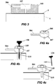
- Figure 3 illustrates an exemplary embodiment of the "well” (107) provided within the patch (105).
- the well is used to provide fluid communication between a delivery tube (504) and the cannula, which after insertion remains in the subcutaneous tissue (4) under the skin (5).
- the delivery tube (504) connects the fluid reservoir (not shown) and the well.
- the needle (not shown in Figure 3 ) passes through the well (107), before it penetrates the skin (5).
- the well (107) allows fluid delivery to the body from the reservoir through the delivery tube and through cannula.
- Figures 4a-c illustrate an exemplary embodiment of the basic principle of the cannula insertion through the well (107). This process can be carried out manually, semi - automatically (the insertion is carried out by the inserter while the patient manually retracts the penetrating member) or automatically (the insertion is carried out by the inserter and the penetrating member is retracted by the inserter).
- Figure 4a illustrates the well (107) having an opening (505) on its upper side and a self sealing rubber on its lower side. The opening allows fluid dripping during priming.
- Figure 4b illustrates a situation in which the penetrating cartridge (150) is inserted into the well (107): the penetrating member and the cannula pierce the rubber septum at the well's lower side and then pierce the skin. Concomitantly, the well-sealing cap (118) closes the opening (505) at the well's upper side.
- Figure 4c illustrates the cannula after insertion and also after the penetrating member (111) has been retracted.
- the well (107) also has an inlet port on its circumference allowing a passage of dispensed fluid from the delivery tube (504) to the cannula (110), through a lateral opening made in the cannula (not shown in Figures 4a-c ).
- the inserter includes an automatic insertion and automatic retracting mechanism.
- the patient first disables all safety mechanisms and then fires the trigger. The firing of the trigger causes an automatic insertion of the penetrating cartridge followed by automatic retraction of the penetrating member.
- FIG 5 shows an exemplary embodiment of an inserter configuration having automatic insertion and retraction capabilities.
- the inserter (100) includes safety mechanisms for preventing misplacement and inadvertent misfiring. This will be explained further in connection with Figures 6 and 7 .
- the inserter also includes a trigger button (330) for actuating a set of springs which fire the penetrating cartridge (150) downward for insertion into the body and for retracting the penetrating member after insertion.
- the inserter is provided with a housing to accommodate all these mechanisms and elements.
- Figure 6 illustrates an exemplary embodiment of the automatic inserter (100) and the position enabling safety mechanism (401).
- An exemplary embodiment of the misfiring safety mechanism (402) is shown in Figure 7 .
- the position enabling safety mechanism (401) is intended for enabling alignment of the inserter (100) with respect to the well and also for preventing misplacement of the inserter on the patch (105).
- the position enabling safety mechanism (401) includes indentation grooves (101), located on the upper part of the patch (105), and matching positioning protrusions (301), provided at the lower side of the inserter housing.
- the positioning protrusions (301) are positioned inside the correwsponding indentation grooves (101), on the patch (105).
- Correct positioning of the positioning protrusions (301) inside the indentation grooves (101), allows the movement of a positioning safety rod (518) in an upward direction, thereby by releasing the trigger and thus allowing the firing.
- the positioning safety rod (518) is locked in a safety position, in which it prevents release of the trigger and thus prevents actuating of the inserter.
- Figure 7 illustrates an exemplary embodiment of the inserter (100) with the misfiring safety mechanism (402), intended for preventing inadvertent actuation of the trigger button (330), according to some embodiments of the present invention.
- the user turns the trigger button (330) of the firing safety mechanism (402) approximately one quarter of a turn (e.g., 90° or thereabout) to release it from the locked position before the trigger button can be pressed for firing.
- the turning of the trigger button (330) is associated with the rotation of a 2-wing butterfly stopper (520) approximately one quarter of a turn (e.g., 90° or thereabout) in the same direction, for example.
- the 2-wing butterfly stopper (520) In its initial position, before it has been turned by one quarter of a turn, the 2-wing butterfly stopper (520) holds a pair of springy latch upper protrusions (524) provided at two protruding shoulders (510), preventing any accidental pressing of the trigger button (330). The turn of the 2-wing butterfly stopper (520) by one quarter of a turn, for example, releases the springy latch upper protrusions (524), allowing for later release of the springy latch upper protrusions (524) off these two protruding shoulders (510).
- the 2-wing butterfly stopper (520) holds the springy latch upper protrusions (524) on the protruding shoulders (510) and this prevents the trigger button (330) from being pressed.
- the misfiring safety mechanism (402) cannot be used before the positioning safety mechanism (401) has been disabled.
- the turning of the trigger button (330) can be possible after the positioning safety mechanism (401) has been disabled by proper placement of the inserter (100) on the patch (105).
- the positioning safety rod (518) is configured to prevent the turn of the 2-wing butterfly stopper (520), thus, preventing the turn of the trigger button (330).
- the trigger button (330) may be fired after all safety mechanisms have been disabled. Insertion is initiated by the patient by pressing the trigger button (330), as shown in Figures 8a-b .
- a set of springs enables the automatic insertion of the penetrating cartridge and automatic retraction of the penetrating member. This set includes a main spring (507), a retraction spring (505), and an expansion spring (512), as shown in Figure 8a .
- the main spring (507) is initially in a loaded state, and is ready to be fired. This spring allows for automatic insertion.
- a cup (521) moves along a slope of a pair of springy latch upper protrusions (524), pushing the springy latch upper protrusions (524) inwards, and releasing them off the two protruding shoulders (510).
- the springy latch upper protrusions (524) are then pushed through a pair of notches (522), causing the loaded main spring (507) to be released and to be shot downwards, as shown in Figure 8b .
- a pair of springy latch intermediate protrusions (526) press on the penetrating cartridge (150), preventing it from shooting down all through its downwards movement.
- the well-sealing cap (118) of the penetrating cartridge (150) enters the well (107) and is retained by means of "O" rings (523).
- the penetrating member (111) and the cannula (110) are both shot through the skin (5) and into the body (4), completing the automatic insertion process.
- the retraction spring (505) is fully stretched and is ready for retraction.
- Figure 9 shows the automatic retraction process for some of the embodiments of the present invention.
- a pair of springy latch lower protrusions (528) is pushed outward by the expansion spring (512) towards a pair of corresponding lower notches (530) provided in the inserter (100).
- the springy latch protrusions (526) move outward as well, releasing the grip portion (116), thus serving as retraction latches.
- the lower end of the retraction spring (505) is connected to the grip portion (116) of the penetrating cartridge.
- the retraction spring (505) pulls the grip portion (116) upward together with the penetrating member (111), while the well sealing cap (118) remains inside the well and the cannula (110) remains inside the body (4). This completes the automatic retraction process.
- the inserter (100) contains the used penetrating member (111) in it.
- the inserter (100) is removed from the patch (105) and is discarded.
- the inserter is provided with an automatic insertion mechanism and is suitable for manual retraction, with an option to reuse the inserter after insertion.
- the user can disable all safety mechanisms and fire the trigger. The firing of the trigger initiates the insertion process of the cannula.
- the penetrating member may be retracted manually.
- the inserter may be reused for insertion several times by loading a fresh penetrating cartridge into the inserter.
- Figure 11 illustrates an exemplary inserter that allows automatic insertion and manual retraction.
- the inserter (100) can be configured to include substantially the same previously -mentioned safety mechanisms for preventing misplacement and misfiring.
- the inserter can also include a trigger button (330); a set of springs, which fire the penetrating cartridge (150) in a downward direction for insertion into the body; and a housing to accommodate all the above mechanisms and elements.
- FIG 12 illustrates an exemplary loading kit (160), which can be used for reloading a penetrating cartridge (150) into the inserter shown in Figure 11 , according to some embodiments of the present invention.
- the loading kit (160) includes a loading cup (162), filled with a spongy material (163) that allows holding a penetrating cartridge (150) within the cup.
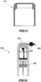
- the inserter can include a safety cup (164), which fits on top of the inserter, and is removed before the insertion process commences.
- Figure 13 illustrates an example of such a safety cup (164) to be fitted on top of the inserter.
- the inserter (100) can include a misfiring safety mechanism (402) for preventing misfiring of the trigger button (330).
- the misfiring safety mechanism (402) can be configured to include a safety pin (603) that prevents the trigger button (330) from being pressed, thereby, preventing misfiring of the penetrating cartridge (150). The user can pull the safety pin (603) of the firing safety mechanism (402) outwardly and remove it in order to release the trigger button.
- a position safety mechanism can be employed also in this configuration, e.g., by adding positioning protrusions to the base of the inserter.
- the protrusions are to be inserted into corresponding matching positioning depressions made on the upper part of the patch so as to ensure proper positioning of the inserter on the patch before the insertion process is initiated.
- the position safety mechanism prevents misplacement of the inserter with respect to the patch, thus, preventing insertion of the penetrating cartridge when it is improperly positioned with respect to the well.
- the trigger button (330) can be fired after all safety mechanisms have been disabled.
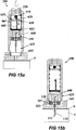
- An insertion process can be initiated by the patient by pressing the trigger button (330), as shown in Figures 15a-b .
- the inserter includes a main spring (507), a main latch (605), a piston (623), and a set of holding arms (608), enabling the automatic insertion of the penetrating cartridge.
- the main spring (507) is initially in a loaded state, and is ready to be fired, and it is the spring that allows for automatic insertion.
- the trigger button (330) When the trigger button (330) is pressed, its vertical displacement causes a protrusion (618) to move down and along the slope of the main latch protrusion (620). This causes the main latch protrusion (620) to move aside and down through an opening (628) in a bridge (629) the latch sits on. This in its turn causes the main latch (605) to be released and to move downward, releasing the main spring (507).
- the main spring (507) is shot downward together with the penetrating cartridge (150) attached to it. This results in the insertion of the penetrating cartridge with the penetrating member through the well provided in the patch (105) and into the skin (5). Throughout its entire movement in a downward direction, the penetrating cartridge (150) is held by a set of holding arms (608), which are connected to the piston (623), as shown in Figure 15a .
- the holding arms (608) reach corresponding matching recesses (625) in the inserter (100), and release the grip portion of the penetrating cartridge (150), as shown in Figure 15b .
- the well sealing cap (118) of the penetrating cartridge (150) enters the well (107) provided in the patch (105) and is retained in the well by means of "O" rings (523).
- the penetrating member (111) and the cannula (110) within the penetrating cartridge (150) are both shot through the skin (5) and into the body (4), thereby completing the automatic insertion process.
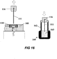
- the inserter (100) may be moved aside and the penetrating member (111) may be manually removed from the patch (105). To do this, the patient holds the grip portion (116) and pulls it out, along the arrow shown in Figure 16 . The used penetrating member (111) is then stuck in the sponge (163) filling the loading cup (162) within the loading kit (160). The loading kit with the used penetrating cartridge is disposed.
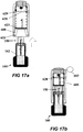
- FIGs 17a-b illustrate exemplary loading of a fresh penetrating cartridge (150) into inserter (100) using a loading kit (160), according to some embodiments of the invention.
- the loading kit includes a loading cup (162) that holds the fresh penetrating cartridge (150) and guards the penetrating member. The cup is pushed by the patient into the inserter (100) through its bottom opening, so that the upper part of the penetrating cartridge (150) pushes against the piston (623), as shown in Figure 17a .
- the penetrating cartridge (150) pushes the piston (623) in an upward direction, causing the holding arms (608) to leave their corresponding recesses (625) and to grip the penetrating cartridge (150), on its way up. In its upward motion, the penetrating cartridge, which pushes the piston (623), also pushes the main latch (605), until the main latch protrusion (620) is captured by the shoulder (628), as shown in Figure 17b .
- the loading cup (162) may be pulled out of the inserter (100), and kept for a later use.
- the loading cup (162) may be used at the end of the insertion process to keep the used penetrating member (111), after its removal from the user's body.
- the patient can insert now the safety pin (603) into a designated place in the trigger button (330), in order to return the misfiring safety mechanism to its enabled state.
- the loading cup (162) cannot be released and pulled out of the inserter (100) until the safety pin (603) is inserted and the misfiring safety mechanism is enabled.
- the inserter is provided with a crank mechanism, allowing automatic insertion and automatic retraction, with an option to reuse the inserter after insertion, according to the present invention.
- the user disables all safety mechanisms and fires the trigger.
- the firing of the trigger initiates the insertion of the cannula by the crank mechanism.
- the crank performs insertion and retraction of the penetrating member, consecutively.
- the inserter may be reused for insertion several times by reloading a fresh penetrating cartridge into the inserter.
- Figures 18a-b illustrate an exemplary crank inserter with an automatic insertion and retraction, according to some embodiments of the invention.
- Figures 18a and 18b are two views of the inserter (100).
- the inserter (100) includes safety mechanisms for preventing misplacement and misfiring; a trigger button (330); a crank mechanism (312), with a cock wheel (320), which while turned causes inserting the penetrating cartridge (150) into the body and retracting the penetrating member after insertion;
- the inserter comprises also a housing to accommodate the above mechanisms and elements.
- a crank mechanism is used for insertion, as shown in Figure 19 .
- the crank mechanism includes a spiral spring (321), a crank (312), and a crank piston (311).
- the end of the crank piston (311) is fitted with the upper connector (313), which connects to the corresponding lower connector (not shown in Figure 19 ), provided in the penetrating cartridge.
- FIG 20 illustrates the loading kit (160) used for reloading a penetrating cartridge (150) into the crank inserter.
- a loading kit (160) can also be provided.
- the loading kit includes a loading cup (162), filled with spongy material (163) that holds a penetrating cartridge (150).
- the top part of the penetrating cartridge (150) is fitted with a lower connector (113), which connects to the corresponding upper connector (not shown in Figure 20 ), provided inside the inserter (100).
- the connectors can be any suitable connectors known in the art, e.g. bayonet connectors.
- the user can load a fresh penetrating cartridge (150) into the inserter (100).
- the fresh cartridge before loading into inserter is stored in the loading kit (160).
- crank (312) is in its initial position (as seen in Fig. 21a ); in another embodiment, the crank (312) is in an extended position (as seen in Fig. 21b ).
- the loading cup (162) can be pushed by the user into the inserter (100) through its bottom open portion, so that the upper part of the penetrating cartridge (150) pushes against the crank piston (311).
- Figures 21a and 21b This is shown in Figures 21a and 21b .
- the loading cup (162) may be pulled out of the inserter (100), by the user, and kept for the later use.
- the loading cup (162) may be used at the end of the insertion process to hold the used penetrating member (111), after insertion to the user's body has been completed.
- the loading of a fresh penetrating cartridge serves as a safety precaution in the crank inserter.
- the crank inserter (100) includes a misfiring safety mechanism (402) for preventing misfiring of the trigger button (330).
- the misfiring safety mechanism (402) is shown in Figures 22a-b .
- the misfiring safety mechanism (402), according to some embodiments of the present invention, includes a cock wheel (320) that can be turned to load a spiral spring (321) and configured to enable the firing. After a fresh penetrating cartridge has been loaded into the inserter, the connector (333) is latched. At this point, the misfiring safety mechanism is held by loading the spiral spring (321). In its initial position, the spiral spring (321) positioned in the inserter is not loaded. Pushing the trigger button (330) before the turning of the cock wheel (320) and loading of the spiral spring (321), prevents firing and thus occasional insertion of the penetrating cartridge (150). The turn of the cock wheel (320) loads the spiral spring (321), which enables firing.
- the user turns the cock wheel (320), which loads the spiral spring (321) against a sprocket wheel (322) latched with a ratchet latch (323), which prevents the release of the spiral spring (321), while it is being loaded, and this prevents accidental firing.
- Figures 22a-b illustrate a front view ( Figure 22a ) and a side view ( Figure 22b ) of the crank inserter (100), with a loaded spiral spring (321) according to some embodiments. Loading the spiral spring (321) places the inserter in a "ready to fire” mode, after which insertion process can commence.
- a position safety mechanism can be added to this embodiment as it has been disclosed in connection with the previous embodiment of the inserter.
- the trigger button (330) of the crank inserter (100) may be fired only after all safety mechanisms have been disabled.
- the insertion process is initiated by the patient, by placement of the crank inserter (100) on the patch (105), when the inserter is in "ready to fire” mode.
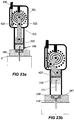
- the insertion process is shown in Figures 23a-b .
- the patient presses the trigger button (330), which releases the ratchet latch (323) from the sprocket wheel (322), thus releasing the spiral spring (321).
- the release of the spiral spring (321) enables the crank (312) to extend, and to push the crank piston (311) vertically downwards.
- the vertical movement of the crank piston (311) which is attached to the upper part of the penetrating cartridge (150) via bayonet connectors (333), pushes the penetrating cartridge (150) downwards, thus allowing for insertion through the patch (105) and into the skin (5). This is shown in Figure 23a .
- the inserter can include a drum that is filled with several penetrating cartridges suitable for automatic insertion.
- the user disables all safety mechanisms and fires the trigger button. The firing of the trigger button initiates the insertion of the cannula. Upon inserting the user turns the drum for firing the next fresh penetrating cartridge, without a need for reloading the drum. When all cartridges have been fired the drum is replenished with a plurality of fresh cartridges.
- a multiple-needle inserter (100) automatically inserts penetrating cartridge (150) into the body.
- the cartridges are taken from drum (815) preloaded with a plurality of penetrating cartridges (for example 6 cartridges). Retraction of the penetrating member is performed manually.
- the inserter can be provided with a protective safety cup (805) which fits on top of the inserter, and is removed before insertion can commence.
- This protective safety cup (805) prevents accidental misfiring.
- Figure 26 illustrates an exemplary safety cup that can be fitted on top of the inserter.
- the cartridge drum (815) includes a revolving needle drum (820) and a plurality of cartridge receiving chambers (817) provided in the drum and situated coaxially with its longitudinal axis (820).
- the penetrating cartridges can be stored in the receiving chambers (817).
- Figure 27 illustrates an exemplary revolving needle drum.
- the inserter (100) includes a main spring (803) and a reloading rod (825), as shown in Figure 28 .
- the user loads the main spring (803) using the reloading rod (825).
- the reloading rod (825) pushes a ram rod (808), provided in the inserter, upward until a ram rod latch (830) is captured by trigger protrusions (827).
- the user then turns the cartridge drum (815) so as to align the loaded chamber with the longitudinal axis of the inserter, until the cartridge drum (815) is captured by an indexing ball (810) and a "click" is heard.
- the user removes the protective safety cup (805), which prevents accidental firing. After completing these steps, the inserter (100) is in a "ready to fire" mode.
- Figures 29a-b illustrate exemplary firing and insertion procedures.
- the user presses the trigger by simultaneously pressing two lateral trigger buttons (330). This releases the ram rod latch (830) from the trigger protrusions (827). This, in turn, releases the main spring (803), which fires downward with the ram rod latch (830), which is in turn stopped by the bracket (832), as shown in Figures 29a and 29b .
- the penetrating cartridge (150) penetrates the patch (105) and enters the well (107) in the patch (105).
- the well sealing cap (118) within the penetrating cartridge (150) is retained by means of "O" rings (not shown) in the well (107); the penetrating member (111) with cannula (110) penetrate the user's skin (5).
- the penetrating member (111) may be manually retracted from the body by holding its grip part (116) and is then disposed of.
- the user places the protective safety cap on the inserter (100) to cover the trigger buttons, to prevent them from being unintentionally pressed.
- the cartridge drum (815) When the cartridge drum (815) is empty, it may be removed by pulling it out from a clamp (839) and disengaging it from the spring ball (837). To reload a new cartridge drum (815), the user removes it from its package, places it at the lower part of the inserter (100) on the spring ball (837) and pushes the clamp (839) inwards.
Landscapes
- Health & Medical Sciences (AREA)
- Life Sciences & Earth Sciences (AREA)
- Physics & Mathematics (AREA)
- Animal Behavior & Ethology (AREA)
- Veterinary Medicine (AREA)
- Public Health (AREA)
- Engineering & Computer Science (AREA)
- Biomedical Technology (AREA)
- Heart & Thoracic Surgery (AREA)
- General Health & Medical Sciences (AREA)
- Pathology (AREA)
- Surgery (AREA)
- Molecular Biology (AREA)
- Medical Informatics (AREA)
- Biophysics (AREA)
- Optics & Photonics (AREA)
- Vascular Medicine (AREA)
- Anesthesiology (AREA)
- Hematology (AREA)
- Emergency Medicine (AREA)
- Infusion, Injection, And Reservoir Apparatuses (AREA)
Claims (12)
- Appareil comprenant :un dispositif (105) de délivrance d'un fluide thérapeutique dans le corps d'un patient et/ou de détection d'un analyte corporel, le dispositif possédant une ouverture configurée comme un puits (107) ; etun dispositif d'insertion (100), comprenant :un carter ayant logé dans celui-ci : au moins une cartouche de pénétration (150) comprenant un élément de pénétration (111) et un élément insérable de manière sous-cutanée (110) ; etun mécanisme de déplacement actionnable manuellement (507) qui à l'actionnement est en mesure d'effectuer une protraction de ladite cartouche de pénétration (111) vers le dispositif de délivrance et/ou de détection, avec la protraction entraînant l'insertion d'au moins l'élément insérable de manière sous-cutanée (1100 dans un compartiment sous-cutané du corps ;avec ledit dispositif d'insertion (100) étant adapté pour l'insertion d'au moins l'élément insérable de manière sous-cutanée (110) dans le compartiment sous-cutané du corps via l'ouverture prévue dans le dispositif de délivrance et/ou de détection et ledit dispositif d'insertion étant adapté pour permettre l'évacuation de l'élément de pénétration (111) depuis le compartiment sous-cutané via ladite ouverture ;caractérisé en ce que ledit dispositif d'insertion comprend en outre une fonction d'autorisation de position qui est un mécanisme de sécurité (401) destiné à empêcher le mécanisme de déplacement d'être actionné quand ladite cartouche de pénétration (150) n'est pas alignée au puits (107) et qui permet l'actionnement du mécanisme de déplacement uniquement quand le dispositif d'insertion (100) a été placé dans une position prédéterminée par rapport au dispositif (105) de délivrance et/ou de détection, ledit mécanisme de sécurité (401) incluant des rainures à indentation (101) sur une surface supérieure du dispositif (105) et des saillies de positionnement correspondantes (101) sur une surface inférieure du carter du dispositif d'insertion (100), avec le positionnement correct des saillies de positionnement (301) à l'intérieur des rainures à indentation (101) permettant le déplacement d'une tige de sécurité (518) pour permettre la protraction de la cartouche de pénétration (150) quand la cartouche de pénétration (150) est alignée au puits (107), avec la tige de sécurité (518) étant verrouillée dans une position de sécurité empêchant l'actionnement du mécanisme de déplacement quand les saillies de positionnement (301) ne sont pas correctement positionnées à l'intérieur des rainures à indentation (101).
- Appareil selon la revendication 1, dans lequel ledit carter est pourvu d'au moins une saillie (301) ; et
ledit dispositif (105) de délivrance et/ou de détection est pourvu d'au moins un creux correspondant (101) entourant le puits (107), de manière à ce qu'à l'insertion de l'au moins une saillie (301) dans l'au moins un creux (101), la cartouche de pénétration (150) soit alignée au puits (107). - Dispositif selon la revendication 1, dans lequel ledit élément insérable de manière sous-cutanée (110) est une canule de délivrance du fluide thérapeutique.
- Dispositif selon la revendication 1, dans lequel ledit élément insérable de manière sous-cutanée (110) est un capteur de détection d'un analyte corporel.
- Appareil selon la revendication 1, dans lequel ledit puits (107) est pivotable.
- Appareil selon la revendication 1, dans lequel le dispositif d'insertion (110) comprend en outre un moyen de rétractation (505) couplé de manière opérationnelle à la cartouche de pénétration (150) et en mesure de rétracter automatiquement l'élément de pénétration (111) depuis le compartiment sous-cutané, tandis que l'élément insérable de manière sous-cutanée (110) est retenu à l'intérieur du compartiment sous-cutané.
- Appareil selon la revendication 1, dans lequel ladite cartouche de pénétration (150) comprend en outre un bouchon d'étanchéité (118) pouvant être reçu dans le puits (107) ;
ledit bouchon d'étanchéité (118) est adapté pour étanchéifier le puits (107) après que l'au moins un élément insérable de manière sous-cutanée (110) a été inséré et après que l'élément de pénétration (111) a été évacué. - Appareil selon la revendication 1, dans lequel le dispositif d'insertion (110) comprend en outre une molette actionnable manuellement (330) destinée à actionner le mécanisme de déplacement ; et
un mécanisme de sécurité anti-déclenchement accidentel (402) destiné à empêcher l'actionnement accidentel de la molette (330). - Appareil selon la revendication 1, dans lequel l'élément de pénétration (111) inclut :une extrémité d'insertion destinée à pénétrer dans le tissu sous-cutané ; etune partie de préhension (116) située face à l'extrémité d'insertion ;dans lequel la partie de préhension (116) permet à l'élément de pénétration (111) de subir une protraction et une rétractation.
- Appareil selon la revendication 1, dans lequel ledit mécanisme de déplacement comprend une manivelle (312) actionnable par une roue dentée.
- Appareil selon la revendication 1, dans lequel l'élément d'insertion (110) comprend en outre un tambour (815) qui est pré-chargeable avec une pluralité de cartouches de pénétration (150) ;
ledit tambour (815) est pourvu d'une pluralité de chambres (817) destinées à recevoir la pluralité de cartouches de pénétration (150) et ledit tambour (815) est déplaçable par rapport au carter de façon à aligner une chambre avec un axe longitudinal du dispositif d'insertion et à permettre la protraction de la cartouche de pénétration reçue dans la chambre. - Appareil selon la revendication 1, dans lequel le dispositif de délivrance et/ou de détection est adhérable sur la peau.
Applications Claiming Priority (2)
| Application Number | Priority Date | Filing Date | Title |
|---|---|---|---|
| US86134506P | 2006-11-28 | 2006-11-28 | |
| PCT/IL2007/001454 WO2008065646A1 (fr) | 2006-11-28 | 2007-11-26 | Dispositif d'insertion et procédé pour insérer un élément insérable de manière sous-cutanée à l'intérieur d'un corps |
Publications (2)
| Publication Number | Publication Date |
|---|---|
| EP2099384A1 EP2099384A1 (fr) | 2009-09-16 |
| EP2099384B1 true EP2099384B1 (fr) | 2018-09-05 |
Family
ID=39271138
Family Applications (1)
| Application Number | Title | Priority Date | Filing Date |
|---|---|---|---|
| EP07827427.1A Active EP2099384B1 (fr) | 2006-11-28 | 2007-11-26 | Dispositif d'insertion et procédé pour insérer un élément insérable de manière sous-cutanée à l'intérieur d'un corps |
Country Status (5)
| Country | Link |
|---|---|
| US (1) | US8696570B2 (fr) |
| EP (1) | EP2099384B1 (fr) |
| DK (1) | DK2099384T3 (fr) |
| ES (1) | ES2690306T3 (fr) |
| WO (1) | WO2008065646A1 (fr) |
Cited By (3)
| Publication number | Priority date | Publication date | Assignee | Title |
|---|---|---|---|---|
| US11273255B2 (en) | 2017-03-31 | 2022-03-15 | Capillary Biomedical, Inc. | Helical insertion infusion device |
| US12214159B2 (en) | 2020-08-28 | 2025-02-04 | Tandem Diabetes Care, Inc | Insulin infusion set |
| US12357751B2 (en) | 2018-11-08 | 2025-07-15 | Tandem Diabetes Care, Inc. | Linear insertion device with rotational drive |
Families Citing this family (194)
| Publication number | Priority date | Publication date | Assignee | Title |
|---|---|---|---|---|
| ATE409057T1 (de) | 2002-02-11 | 2008-10-15 | Antares Pharma Inc | Intradermales injektionsgerät |
| US7381184B2 (en) | 2002-11-05 | 2008-06-03 | Abbott Diabetes Care Inc. | Sensor inserter assembly |
| US20190357827A1 (en) | 2003-08-01 | 2019-11-28 | Dexcom, Inc. | Analyte sensor |
| USD914881S1 (en) | 2003-11-05 | 2021-03-30 | Abbott Diabetes Care Inc. | Analyte sensor electronic mount |
| US7883464B2 (en) | 2005-09-30 | 2011-02-08 | Abbott Diabetes Care Inc. | Integrated transmitter unit and sensor introducer mechanism and methods of use |
| US9398882B2 (en) | 2005-09-30 | 2016-07-26 | Abbott Diabetes Care Inc. | Method and apparatus for providing analyte sensor and data processing device |
| US9351669B2 (en) | 2009-09-30 | 2016-05-31 | Abbott Diabetes Care Inc. | Interconnect for on-body analyte monitoring device |
| US9572534B2 (en) | 2010-06-29 | 2017-02-21 | Abbott Diabetes Care Inc. | Devices, systems and methods for on-skin or on-body mounting of medical devices |
| US9743862B2 (en) | 2011-03-31 | 2017-08-29 | Abbott Diabetes Care Inc. | Systems and methods for transcutaneously implanting medical devices |
| US9259175B2 (en) | 2006-10-23 | 2016-02-16 | Abbott Diabetes Care, Inc. | Flexible patch for fluid delivery and monitoring body analytes |
| US7731657B2 (en) | 2005-08-30 | 2010-06-08 | Abbott Diabetes Care Inc. | Analyte sensor introducer and methods of use |
| US9788771B2 (en) | 2006-10-23 | 2017-10-17 | Abbott Diabetes Care Inc. | Variable speed sensor insertion devices and methods of use |
| US9636450B2 (en) | 2007-02-19 | 2017-05-02 | Udo Hoss | Pump system modular components for delivering medication and analyte sensing at seperate insertion sites |
| US7697967B2 (en) | 2005-12-28 | 2010-04-13 | Abbott Diabetes Care Inc. | Method and apparatus for providing analyte sensor insertion |
| US10226207B2 (en) | 2004-12-29 | 2019-03-12 | Abbott Diabetes Care Inc. | Sensor inserter having introducer |
| US20100331646A1 (en) * | 2009-06-30 | 2010-12-30 | Abbott Diabetes Care Inc. | Health Management Devices and Methods |
| US20090105569A1 (en) | 2006-04-28 | 2009-04-23 | Abbott Diabetes Care, Inc. | Introducer Assembly and Methods of Use |
| US8029441B2 (en) | 2006-02-28 | 2011-10-04 | Abbott Diabetes Care Inc. | Analyte sensor transmitter unit configuration for a data monitoring and management system |
| US8571624B2 (en) | 2004-12-29 | 2013-10-29 | Abbott Diabetes Care Inc. | Method and apparatus for mounting a data transmission device in a communication system |
| US8333714B2 (en) | 2006-09-10 | 2012-12-18 | Abbott Diabetes Care Inc. | Method and system for providing an integrated analyte sensor insertion device and data processing unit |
| US8512243B2 (en) | 2005-09-30 | 2013-08-20 | Abbott Diabetes Care Inc. | Integrated introducer and transmitter assembly and methods of use |
| US8545403B2 (en) | 2005-12-28 | 2013-10-01 | Abbott Diabetes Care Inc. | Medical device insertion |
| WO2006079064A1 (fr) | 2005-01-24 | 2006-07-27 | Antares Pharma, Inc. | Injecteur a seringue preremplie assiste d'une aiguille |
| PT1762259E (pt) | 2005-09-12 | 2010-12-10 | Unomedical As | Insersor para um conjunto de infusão com uma primeira e uma segunda unidades de mola |
| US9521968B2 (en) | 2005-09-30 | 2016-12-20 | Abbott Diabetes Care Inc. | Analyte sensor retention mechanism and methods of use |
| US8880138B2 (en) | 2005-09-30 | 2014-11-04 | Abbott Diabetes Care Inc. | Device for channeling fluid and methods of use |
| EP2077128B1 (fr) | 2005-12-23 | 2010-12-22 | Unomedical A/S | Dispositif d'injection |
| US11298058B2 (en) | 2005-12-28 | 2022-04-12 | Abbott Diabetes Care Inc. | Method and apparatus for providing analyte sensor insertion |
| US7736310B2 (en) | 2006-01-30 | 2010-06-15 | Abbott Diabetes Care Inc. | On-body medical device securement |
| US9211379B2 (en) | 2006-02-28 | 2015-12-15 | Unomedical A/S | Inserter for infusion part and infusion part provided with needle protector |
| US7826879B2 (en) | 2006-02-28 | 2010-11-02 | Abbott Diabetes Care Inc. | Analyte sensors and methods of use |
| US8251947B2 (en) | 2006-05-03 | 2012-08-28 | Antares Pharma, Inc. | Two-stage reconstituting injector |
| WO2007131025A1 (fr) | 2006-05-03 | 2007-11-15 | Antares Pharma, Inc. | Injecteur à dosage réglable |
| EP2023818A2 (fr) | 2006-06-07 | 2009-02-18 | Unomedical A/S | Appareil à insérer |
| US8790311B2 (en) | 2006-06-09 | 2014-07-29 | Unomedical A/S | Mounting pad |
| AU2007280850B9 (en) | 2006-08-02 | 2010-09-02 | Unomedical A/S | Cannula and delivery device |
| US8932216B2 (en) | 2006-08-07 | 2015-01-13 | Abbott Diabetes Care Inc. | Method and system for providing data management in integrated analyte monitoring and infusion system |
| CN102743179B (zh) * | 2006-12-22 | 2016-03-16 | F·霍夫曼-拉罗氏股份公司 | 带体内电化学分析物感测的流体传输 |
| HUE065834T2 (hu) | 2007-04-10 | 2024-06-28 | Hoffmann La Roche | Készülék és eljárás folyadék szivattyúzására |
| US8456301B2 (en) | 2007-05-08 | 2013-06-04 | Abbott Diabetes Care Inc. | Analyte monitoring system and methods |
| ES3038412T3 (en) | 2007-05-11 | 2025-10-13 | Hoffmann La Roche | A positive displacement pump |
| WO2008150917A1 (fr) | 2007-05-31 | 2008-12-11 | Abbott Diabetes Care, Inc. | Dispositifs d'insertion et procédés |
| RU2469751C2 (ru) | 2007-06-20 | 2012-12-20 | Уномедикал А/С | Способ изготовления катетера и устройство для его осуществления |
| US8002752B2 (en) | 2007-06-25 | 2011-08-23 | Medingo, Ltd. | Protector apparatus |
| US8641618B2 (en) | 2007-06-27 | 2014-02-04 | Abbott Diabetes Care Inc. | Method and structure for securing a monitoring device element |
| US8160900B2 (en) | 2007-06-29 | 2012-04-17 | Abbott Diabetes Care Inc. | Analyte monitoring and management device and method to analyze the frequency of user interaction with the device |
| JP2010531692A (ja) | 2007-07-03 | 2010-09-30 | ウノメディカル アクティーゼルスカブ | 双安定均衡状態を持つ挿入器 |
| AU2008274311A1 (en) | 2007-07-10 | 2009-01-15 | Unomedical A/S | Inserter having two springs |
| CA2694952A1 (fr) | 2007-07-18 | 2009-01-22 | Unomedical A/S | Dispositif d'insertion a action pivotante |
| EP2227132B1 (fr) | 2007-10-09 | 2023-03-08 | DexCom, Inc. | Système d'administration d'insuline intégré avec un capteur de glucose en continu |
| AU2009214047A1 (en) * | 2008-02-13 | 2009-08-20 | Unomedical A/S | Sealing between a cannula part and a fluid path |
| MX2010009087A (es) | 2008-02-20 | 2011-05-03 | Unomedical As | Dispositivo de insercion con parte horizontalmente movil. |
| JP5731829B2 (ja) | 2008-03-10 | 2015-06-10 | アンタレス・ファーマ・インコーポレーテッド | 注射器安全装置 |
| EP3581224A1 (fr) | 2008-08-05 | 2019-12-18 | Antares Pharma, Inc. | Injecteur à dosage multiple |
| US9370621B2 (en) * | 2008-12-16 | 2016-06-21 | Medtronic Minimed, Inc. | Needle insertion systems and methods |
| WO2010072664A1 (fr) | 2008-12-22 | 2010-07-01 | Unomedical A/S | Dispositif médical comprenant un tampon adhésif |
| EP2201968A1 (fr) * | 2008-12-24 | 2010-06-30 | Roche Diagnostics GmbH | Système d'insertion et dispositif d'insertion |
| US9402544B2 (en) | 2009-02-03 | 2016-08-02 | Abbott Diabetes Care Inc. | Analyte sensor and apparatus for insertion of the sensor |
| AU2010226442A1 (en) | 2009-03-20 | 2011-10-13 | Antares Pharma, Inc. | Hazardous agent injection system |
| EP2272553A1 (fr) * | 2009-06-29 | 2011-01-12 | Unomedical A/S | Ensemble d'insertion |
| EP2272554A1 (fr) * | 2009-06-29 | 2011-01-12 | Unomedical A/S | Dispositif d'insertion |
| EP2425209A4 (fr) | 2009-04-29 | 2013-01-09 | Abbott Diabetes Care Inc | Procédé et système pour fournir un étalonnage de détecteur d'analyte en temps réel avec remplissage rétrospectif |
| WO2010138856A1 (fr) | 2009-05-29 | 2010-12-02 | Abbott Diabetes Care Inc. | Systèmes d'antenne de dispositif médical comportant des configurations d'antenne externe |
| RU2012107433A (ru) | 2009-07-30 | 2013-09-10 | Уномедикал А/С | Устройство для введения с горизонтальной движущейся частью |
| US9533092B2 (en) | 2009-08-07 | 2017-01-03 | Unomedical A/S | Base part for a medication delivery device |
| WO2011025549A1 (fr) | 2009-08-31 | 2011-03-03 | Abbott Diabetes Care Inc. | Dispositifs et procédés médicaux |
| US20110082484A1 (en) * | 2009-10-07 | 2011-04-07 | Heber Saravia | Sensor inserter assembly having rotatable trigger |
| EP2327433B1 (fr) * | 2009-11-26 | 2012-04-18 | F. Hoffmann-La Roche AG | Ensemble de canule pouvant être déclenchée de manière externe |
| US9339599B2 (en) | 2009-12-21 | 2016-05-17 | Sorin Group Usa, Inc. | Self-dilating cannula |
| USD924406S1 (en) | 2010-02-01 | 2021-07-06 | Abbott Diabetes Care Inc. | Analyte sensor inserter |
| CA2766685A1 (fr) | 2010-03-24 | 2011-12-29 | Abbott Diabetes Care Inc. | Appareils d'insertion de dispositifs medicaux et procedes d'insertion et d'utilisation de dispositifs medicaux |
| JP2013523233A (ja) | 2010-03-30 | 2013-06-17 | ウノメディカル アクティーゼルスカブ | 医療デバイス |
| US11064921B2 (en) | 2010-06-29 | 2021-07-20 | Abbott Diabetes Care Inc. | Devices, systems and methods for on-skin or on-body mounting of medical devices |
| CN103167887B (zh) * | 2010-08-27 | 2015-07-15 | 诺沃—诺迪斯克有限公司 | 医用注射装置 |
| US8915879B2 (en) | 2010-09-24 | 2014-12-23 | Perqflo, Llc | Infusion pumps |
| EP2433663A1 (fr) | 2010-09-27 | 2012-03-28 | Unomedical A/S | Système d'insertion |
| EP2436412A1 (fr) | 2010-10-04 | 2012-04-04 | Unomedical A/S | Canule d'arroseur |
| US8905972B2 (en) * | 2010-11-20 | 2014-12-09 | Perqflo, Llc | Infusion pumps |
| US8814831B2 (en) | 2010-11-30 | 2014-08-26 | Becton, Dickinson And Company | Ballistic microneedle infusion device |
| CA2828873C (fr) * | 2011-02-09 | 2020-07-14 | Becton, Dickinson And Company | Dispositif de perfusion a insertion et retraction automatique d'aiguille d'intubateur |
| US8795253B2 (en) | 2011-04-05 | 2014-08-05 | Sorin Group Italia S.R.L. | Bi-directional perfusion cannula |
| IL212263A (en) | 2011-04-11 | 2014-01-30 | Alexander Kalnitskiy | An intramuscular device for inserting a tube into a bone |
| US9848809B2 (en) | 2011-04-15 | 2017-12-26 | Dexcom, Inc. | Advanced analyte sensor calibration and error detection |
| ITFI20110116A1 (it) * | 2011-06-07 | 2012-12-08 | Mattia Glauber | Arterial cannula for cardiac surgery.cannula arteriosa per chirurgia cardiaca. |
| US9220660B2 (en) | 2011-07-15 | 2015-12-29 | Antares Pharma, Inc. | Liquid-transfer adapter beveled spike |
| US8496619B2 (en) | 2011-07-15 | 2013-07-30 | Antares Pharma, Inc. | Injection device with cammed ram assembly |
| EP2763723B1 (fr) | 2011-10-05 | 2016-04-13 | Unomedical A/S | Introducteur pour insertion simultanée de plusieurs éléments transcutanés |
| EP2583715A1 (fr) | 2011-10-19 | 2013-04-24 | Unomedical A/S | Système de tube de perfusion et procédé de fabrication |
| US9440051B2 (en) | 2011-10-27 | 2016-09-13 | Unomedical A/S | Inserter for a multiplicity of subcutaneous parts |
| US9317656B2 (en) | 2011-11-23 | 2016-04-19 | Abbott Diabetes Care Inc. | Compatibility mechanisms for devices in a continuous analyte monitoring system and methods thereof |
| WO2013090215A2 (fr) | 2011-12-11 | 2013-06-20 | Abbot Diabetes Care Inc. | Dispositifs détecteurs d'analytes, connexions, et procédés |
| PT2822618T (pt) | 2012-03-06 | 2024-03-04 | Antares Pharma Inc | Seringa pré-cheia com característica de força de rutura |
| JP6051204B2 (ja) | 2012-03-22 | 2016-12-27 | テルモ株式会社 | 穿刺装置及び薬液投与装置 |
| EP2833944A4 (fr) | 2012-04-06 | 2016-05-25 | Antares Pharma Inc | Administration par injection par jet assistée par une aiguille de compositions de testostérone |
| US9364610B2 (en) | 2012-05-07 | 2016-06-14 | Antares Pharma, Inc. | Injection device with cammed ram assembly |
| EP2668901A1 (fr) * | 2012-05-31 | 2013-12-04 | Roche Diagniostics GmbH | Ensemble d'insertion de capteur, cartouche de capteur et dispositif d'insertion |
| EP2668902A1 (fr) | 2012-05-31 | 2013-12-04 | Roche Diagniostics GmbH | Cartouche de capteur et dispositif d'insertion |
| EP2705863A1 (fr) * | 2012-09-11 | 2014-03-12 | Sanofi-Aventis Deutschland GmbH | Dispositif d'administration de médicament avec mécanisme de détection d'alignement d'aiguille |
| EP2898828B1 (fr) * | 2012-09-24 | 2019-04-03 | Terumo Kabushiki Kaisha | Dispositif d'insertion de capteur |
| US9731069B2 (en) | 2012-09-27 | 2017-08-15 | Becton, Dickinson And Company | Perpendicular infusion set and disposable inserter |
| DE102012019400A1 (de) * | 2012-10-04 | 2014-04-10 | Gerresheimer Regensburg Gmbh | Stechhilfevorrichtung zur Blutprobenentnahme |
| LT2908887T (lt) * | 2012-10-19 | 2018-08-10 | Eli Lilly And Company | Automatinis įšvirkštimo įrenginys su paleidimo konstrukcija |
| PT2953667T (pt) | 2013-02-11 | 2020-01-28 | Antares Pharma Inc | Dispositivo de injeção a jato auxiliado por agulha tendo força de gatilho reduzida |
| JP6030803B2 (ja) | 2013-03-11 | 2016-11-24 | アンタレス・ファーマ・インコーポレーテッド | ピニオンシステムを有する用量注射器 |
| WO2014165136A1 (fr) | 2013-03-12 | 2014-10-09 | Antares Pharma, Inc. | Seringues pré-remplies à volume constant et leurs trousses |
| EP2832390A1 (fr) | 2013-07-30 | 2015-02-04 | Sensile Pat AG | Dispositif d'administration de médicament avec mécanisme d'actionnement d'aiguilles |
| TR201902956T4 (tr) * | 2013-09-05 | 2019-03-21 | Sanofi Aventis Deutschland | Bir iğne yerleştirme düzeneğine yönelik tahrik mekanizması. |
| DE102013224431B4 (de) * | 2013-11-28 | 2015-06-18 | 4A Engineering Gmbh | Setzhilfe zum Setzen eines Katheters für Diabetiker |
| US10441717B2 (en) | 2014-04-15 | 2019-10-15 | Insulet Corporation | Monitoring a physiological parameter associated with tissue of a host to confirm delivery of medication |
| JP6616327B2 (ja) * | 2014-04-24 | 2019-12-04 | ベクトン・ディキンソン・アンド・カンパニー | 流体注入デバイス |
| EP3145561A1 (fr) | 2014-05-20 | 2017-03-29 | Cequr SA | Dispositif d'administration d'un médicament ayant un orifice de remplissage à accès restreint |
| US9999542B2 (en) * | 2014-07-16 | 2018-06-19 | Doheny Eye Institute | Systems, methods, and devices for cannula insertion |
| EP3171780B1 (fr) * | 2014-07-22 | 2018-04-25 | Roche Diabetes Care GmbH | Dispositif d'insertion avec verrou de sécurité |
| US10194842B2 (en) | 2014-09-03 | 2019-02-05 | Nova Biomedical Corporation | Subcutaneous sensor inserter and method |
| CN107278158A (zh) * | 2014-09-29 | 2017-10-20 | 尤尼特拉克特注射器控股有限公司 | 用于药物输送泵的刚性针插入机构 |
| US10159786B2 (en) | 2014-09-30 | 2018-12-25 | Perqflo, Llc | Hybrid ambulatory infusion pumps |
| US12178992B2 (en) | 2014-09-30 | 2024-12-31 | Medtronic Minimed, Inc. | Different disposable assemblies for the same reusable assembly |
| JP6618486B2 (ja) | 2015-01-27 | 2019-12-11 | テルモ株式会社 | センサ挿入装置及びセンサ挿入装置セット |
| EP3650060B1 (fr) | 2015-02-18 | 2021-09-29 | Medtronic Minimed, Inc. | Pompes de perfusion ambulatoire et ensembles réservoirs destinés à être utilisés avec celles-ci |
| CN107205702B (zh) * | 2015-03-11 | 2020-05-01 | 泰尔茂株式会社 | 传感器插入装置以及更换件 |
| US10213139B2 (en) | 2015-05-14 | 2019-02-26 | Abbott Diabetes Care Inc. | Systems, devices, and methods for assembling an applicator and sensor control device |
| AU2016260547B2 (en) | 2015-05-14 | 2020-09-03 | Abbott Diabetes Care Inc. | Compact medical device inserters and related systems and methods |
| WO2016191302A1 (fr) * | 2015-05-22 | 2016-12-01 | Dexcom, Inc. | Aiguille pour administration par capteur d'analyte transcutané |
| ES2753453T3 (es) | 2015-05-26 | 2020-04-08 | Hoffmann La Roche | Cartucho e insertador para un sistema médico |
| CZ306565B6 (cs) * | 2015-11-20 | 2017-03-08 | ChemProtect.SK s.r.o. | Autoinjektor |
| EP3804611B1 (fr) | 2015-12-30 | 2024-07-17 | Dexcom, Inc. | Systèmes et procédés de capteur d'analyte transcutané |
| WO2017139723A1 (fr) | 2016-02-12 | 2017-08-17 | Perqflo, Llc | Pompes à perfusion ambulatoires et ensembles à utiliser avec celle-ci |
| US9827369B2 (en) * | 2016-03-16 | 2017-11-28 | Baxter International Inc. | Percutaneous administration device and method for injecting medicinal substances |
| AU2017257665B2 (en) | 2016-04-29 | 2022-02-03 | Icu Medical, Inc. | Subcutaneous insertion systems, devices and related methods |
| US10980522B2 (en) | 2016-10-18 | 2021-04-20 | Piper Access, Llc | Intraosseous access devices, systems, and methods |
| AU2017357745B2 (en) | 2016-11-11 | 2023-05-11 | Insulet Corporation | Drug delivery systems with sealed and sterile fluid paths and methods of providing the same |
| CN115444410B (zh) | 2017-01-23 | 2025-08-15 | 雅培糖尿病护理公司 | 用于插入体内分析物传感器的施加器及组件 |
| EP3568083B1 (fr) | 2017-03-07 | 2021-04-28 | Piper Access, LLC. | Protecteurs pour instruments allongés et systèmes associés |
| JP7169984B2 (ja) | 2017-03-10 | 2022-11-11 | パイパー・アクセス、エルエルシー | 固定装置、固定システム、及び固定方法 |
| EP3612258A4 (fr) * | 2017-04-19 | 2021-01-06 | Metronom Health, Inc. | Dispositif d'insertion pour capteurs d'analyte |
| EP3928688B1 (fr) | 2017-06-23 | 2022-06-01 | Dexcom, Inc. | Capteurs de substance à analyser transcutanés, applicateurs correspondants et moyeu d'aiguille comprenant une fonction anti-rotation |
| US11260171B2 (en) | 2017-07-04 | 2022-03-01 | Medtronic Minimed, Inc. | Ambulatory infusion pumps and assemblies for use with same |
| US10722640B2 (en) | 2017-08-03 | 2020-07-28 | Insulet Corporation | Devices, systems, and methods of packaging for a pre-filled drug delivery device |
| US10973939B2 (en) | 2017-08-03 | 2021-04-13 | Insulet Corporation | System and method for aseptic packaging of a drug delivery device components |
| FI3668400T3 (fi) | 2017-08-18 | 2023-08-29 | Abbott Diabetes Care Inc | Menetelmä analyyttianturien yksilölliseen kalibrointiin |
| WO2019060839A1 (fr) * | 2017-09-25 | 2019-03-28 | Insulet Corporation | Dispositif d'administration de médicament à cartouche préremplie |
| US11331022B2 (en) | 2017-10-24 | 2022-05-17 | Dexcom, Inc. | Pre-connected analyte sensors |
| EP3928687B1 (fr) | 2017-10-24 | 2024-06-26 | Dexcom, Inc. | Dispositif portable avec un capteur d'analyte préconnecté |
| US12409278B2 (en) | 2017-12-21 | 2025-09-09 | Becton, Dickinson And Company | Device for facilitating needle injection |
| DE102018101283A1 (de) * | 2018-01-22 | 2019-07-25 | Eyesense Gmbh | Injektor zum transkutanen Einführen eines Sensors in einen Patienten |
| ES2953372T3 (es) | 2018-02-20 | 2023-11-10 | Piper Access Llc | Dispositivos de perforación y métodos relacionados |
| AU2019282729B2 (en) | 2018-06-07 | 2022-03-17 | Abbott Diabetes Care Inc. | Focused sterilization and sterilized sub-assemblies for analyte monitoring systems |
| DE202019005660U1 (de) * | 2018-06-07 | 2021-07-12 | Abbott Diabetes Care, Inc. | Fokussierte Sterilisation und sterilisierte Teilanordnungen für Analytüberwachungssysteme |
| USD926325S1 (en) | 2018-06-22 | 2021-07-27 | Dexcom, Inc. | Wearable medical monitoring device |
| CN110755088B (zh) * | 2018-07-27 | 2022-07-26 | 华广生技股份有限公司 | 弹性生理贴片 |
| US11241532B2 (en) | 2018-08-29 | 2022-02-08 | Insulet Corporation | Drug delivery system with sensor having optimized communication and infusion site |
| KR102222049B1 (ko) * | 2018-09-27 | 2021-03-04 | 주식회사 아이센스 | 연속 혈당 측정 장치용 어플리케이터 |
| WO2020131159A1 (fr) | 2018-12-21 | 2020-06-25 | Abbott Diabetes Care Inc. | Systèmes, dispositifs et procédés d'insertion de capteur d'analyte |
| US12364819B2 (en) | 2019-02-12 | 2025-07-22 | Eli Lilly And Company | Fluidic subsystem for multi-use drug-delivery device |
| CA3208266C (fr) | 2019-02-22 | 2024-04-16 | Deka Products Limited Partnership | Ensemble de perfusion, systemes d'ensemble d'insertion et procedes |
| US12539361B2 (en) | 2019-02-22 | 2026-02-03 | Deka Products Limited Partnership | Infusion set and inserter assembly apparatuses, systems, and methods |
| US11317867B2 (en) | 2019-04-23 | 2022-05-03 | Medtronic Minimed, Inc. | Flexible physiological characteristic sensor assembly |
| US11224361B2 (en) * | 2019-04-23 | 2022-01-18 | Medtronic Minimed, Inc. | Flexible physiological characteristic sensor assembly |
| KR102237092B1 (ko) * | 2019-04-30 | 2021-04-13 | 주식회사 아이센스 | 연속 혈당 측정 장치용 어플리케이터 |
| USD1002852S1 (en) | 2019-06-06 | 2023-10-24 | Abbott Diabetes Care Inc. | Analyte sensor device |
| CA3088622C (fr) | 2019-08-02 | 2023-01-03 | Chun-Mu Huang | Dispositif d`insertion pour un biocapteur et methode d`insertion |
| US11678846B2 (en) | 2019-08-02 | 2023-06-20 | Bionime Corporation | Insertion device for a biosensor |
| JP7102469B2 (ja) | 2019-08-02 | 2022-07-19 | 華廣生技股▲ふん▼有限公司 | センサーを搭載するための容器及びその操作方法 |
| US12427253B2 (en) * | 2019-08-02 | 2025-09-30 | Bionime Corporation | Insertion device for a biosensor and insertion method thereof |
| US11896804B2 (en) | 2019-08-02 | 2024-02-13 | Bionime Corporation | Insertion device for a biosensor and insertion method thereof |
| CN115361981A (zh) | 2020-01-30 | 2022-11-18 | 塞卡科实验室有限公司 | 冗余交错式葡萄糖传感器疾病管理系统 |
| CN115867333B (zh) * | 2020-07-07 | 2025-12-16 | 英赛罗公司 | 输注泵部署系统及方法 |
| US12335342B2 (en) | 2020-07-21 | 2025-06-17 | Abbott Diabetes Care Inc. | Transmitting analyte data using low-power instruction sets |
| CN115942909A (zh) | 2020-08-31 | 2023-04-07 | 雅培糖尿病护理公司 | 用于分析物传感器插入的系统、装置和方法 |
| AU2021333936A1 (en) | 2020-08-31 | 2023-01-05 | Abbott Diabetes Care Inc. | Secured communications in medical monitoring systems |
| ES3000715T3 (en) | 2020-09-15 | 2025-03-03 | Abbott Diabetes Care Inc | Device for analyte monitoring |
| JP2023541266A (ja) | 2020-09-15 | 2023-09-29 | アボット ダイアベティス ケア インコーポレイテッド | 検体センサのためのシステム、デバイス、及び方法 |
| WO2022072823A2 (fr) | 2020-10-02 | 2022-04-07 | Insulet Corporation | Dispositif de distribution de liquide comportant de multiples éléments pénétrants |
| US11951281B2 (en) | 2020-11-11 | 2024-04-09 | Medtronic Minimed, Inc. | Fluid conduit insertion devices |
| US12447269B2 (en) * | 2020-11-11 | 2025-10-21 | Medtronic Minimed, Inc. | Torsional insertion devices |
| EP4262921A1 (fr) | 2020-12-18 | 2023-10-25 | Insulet Corporation | Patin adhésif à bobine métallique pour fixer un dispositif médical sur le corps |
| USD999913S1 (en) | 2020-12-21 | 2023-09-26 | Abbott Diabetes Care Inc | Analyte sensor inserter |
| CN116709978A (zh) | 2020-12-31 | 2023-09-05 | 雅培糖尿病护理公司 | 医疗监测系统中的嵌入式系统 |
| EP4346945A1 (fr) | 2021-05-28 | 2024-04-10 | Insulet Corporation | Capteurs d'état à base de ressort |
| US12496398B2 (en) | 2021-05-28 | 2025-12-16 | Insulet Corporation | Threshold based automatic glucose control response |
| US12406760B2 (en) | 2021-06-07 | 2025-09-02 | Insulet Corporation | Exercise safety prediction based on physiological conditions |
| MY202051A (en) | 2021-07-16 | 2024-03-30 | Abbott Diabetes Care Inc | Systems, devices, and methods for analyte monitoring |
| CR20240092A (es) | 2021-07-21 | 2024-06-13 | Abbott Diabetes Care Inc | Programación por aire de los dispositivos de detección |
| USD1107897S1 (en) | 2021-08-26 | 2025-12-30 | Deka Products Limited Partnership | Infusion set component and adhering assembly combination |
| USD1013864S1 (en) | 2021-08-26 | 2024-02-06 | Deka Products Limited Partnership | Fluid administration apparatus assembly |
| WO2023043814A2 (fr) | 2021-09-15 | 2023-03-23 | Abbott Diabetes Care Inc. | Système de connectivité d'analyte modulaire pour une communication extensible avec différents types de capteurs physiologiques |
| WO2023044887A1 (fr) * | 2021-09-27 | 2023-03-30 | Medtrum Technologies Inc. | Unité d'installation d'un dispositif de détection d'analyte et procédé d'utilisation |
| CN118043903A (zh) | 2021-09-29 | 2024-05-14 | 雅培糖尿病护理公司 | 分析物数据接收设备的移动应用更新 |
| US12478738B2 (en) | 2021-11-04 | 2025-11-25 | Insulet Corporation | Methods and systems for sterilizing sealed components of a drug delivery device |
| US20240408304A1 (en) * | 2021-11-12 | 2024-12-12 | Aita Bio Inc. | Device for delivering medicament with integrated infusion catheter and continous glucose monitor sensor assembly |
| USD1057941S1 (en) | 2022-08-26 | 2025-01-14 | Deka Products Limited Partnership | Patient care assembly component |
| USD1043976S1 (en) | 2022-08-26 | 2024-09-24 | Deka Products Limited Partnership | Fluid transfer connector |
| EP4356943B1 (fr) * | 2022-10-21 | 2026-03-18 | Sensile Medical AG | Dispositif d'administration de médicament |
| EP4698058A1 (fr) * | 2023-04-19 | 2026-02-25 | F. Hoffmann-La Roche AG | Dispositif d'insertion |
Citations (11)
| Publication number | Priority date | Publication date | Assignee | Title |
|---|---|---|---|---|
| WO2003090509A2 (fr) * | 2002-04-23 | 2003-11-06 | Insulet Corporation | Systeme d'administration de fluide par voie transcutanee |
| WO2004024211A2 (fr) * | 2002-09-12 | 2004-03-25 | Children's Hospital Medical Center | Procede et dispositif d'injection indolore de medicament |
| US20040133164A1 (en) * | 2002-11-05 | 2004-07-08 | Funderburk Jeffery V. | Sensor inserter device and methods of use |
| US20040158207A1 (en) * | 2001-04-06 | 2004-08-12 | Marcel Hunn | Infusion set |
| US20040162521A1 (en) * | 2002-10-07 | 2004-08-19 | Henrik Bengtsson | Needle device comprising a plurality of needles |
| US20050101912A1 (en) * | 2003-11-10 | 2005-05-12 | Mark Faust | Device and method for insertion of a cannula of an infusion device |
| WO2005065748A1 (fr) * | 2003-12-30 | 2005-07-21 | Disetronic Licensing Ag | Dispositif d'insertion pour dispositifs de perforation |
| GB2414398A (en) * | 2004-05-28 | 2005-11-30 | Cilag Ag Int | Injection Device. |
| WO2005112800A2 (fr) * | 2004-05-17 | 2005-12-01 | Tiax Llc | Dispositif d'infusion intraosseuse |
| WO2006015600A2 (fr) * | 2004-08-10 | 2006-02-16 | Unomedical A/S | Dispositif de canule |
| WO2006061354A1 (fr) * | 2004-12-06 | 2006-06-15 | Novo Nordisk A/S | Systeme ventile pouvant etre monte sur la peau |
Family Cites Families (17)
| Publication number | Priority date | Publication date | Assignee | Title |
|---|---|---|---|---|
| US4755173A (en) * | 1986-02-25 | 1988-07-05 | Pacesetter Infusion, Ltd. | Soft cannula subcutaneous injection set |
| US5176662A (en) * | 1990-08-23 | 1993-01-05 | Minimed Technologies, Ltd. | Subcutaneous injection set with improved cannula mounting arrangement |
| US5257980A (en) * | 1993-04-05 | 1993-11-02 | Minimed Technologies, Ltd. | Subcutaneous injection set with crimp-free soft cannula |
| US5540664A (en) * | 1993-05-27 | 1996-07-30 | Washington Biotech Corporation | Reloadable automatic or manual emergency injection system |
| US5390671A (en) * | 1994-03-15 | 1995-02-21 | Minimed Inc. | Transcutaneous sensor insertion set |
| US5611806A (en) * | 1994-05-23 | 1997-03-18 | Samsung Electro-Mechanics Co., Ltd. | Skin perforating device for transdermal medication |
| IE72524B1 (en) * | 1994-11-04 | 1997-04-23 | Elan Med Tech | Analyte-controlled liquid delivery device and analyte monitor |
| US5586553A (en) * | 1995-02-16 | 1996-12-24 | Minimed Inc. | Transcutaneous sensor insertion set |
| US5568806A (en) * | 1995-02-16 | 1996-10-29 | Minimed Inc. | Transcutaneous sensor insertion set |
| US6093172A (en) * | 1997-02-05 | 2000-07-25 | Minimed Inc. | Injector for a subcutaneous insertion set |
| DK1695727T3 (da) * | 2000-11-09 | 2008-12-01 | Insulet Corp | Anordning til transkutan administrering |
| US6830562B2 (en) * | 2001-09-27 | 2004-12-14 | Unomedical A/S | Injector device for placing a subcutaneous infusion set |
| ATE446112T1 (de) * | 2003-12-18 | 2009-11-15 | Tecpharma Licensing Ag | Auslösbares injektionsgerät |
| US8989833B2 (en) * | 2004-07-13 | 2015-03-24 | Dexcom, Inc. | Transcutaneous analyte sensor |
| US20060263839A1 (en) * | 2005-05-17 | 2006-11-23 | Isense Corporation | Combined drug delivery and analyte sensor apparatus |
| US7935104B2 (en) * | 2005-11-07 | 2011-05-03 | Medingo, Ltd. | Systems and methods for sustained medical infusion and devices related thereto |
| US8435211B2 (en) * | 2006-07-24 | 2013-05-07 | Medingo Ltd. | Systems, devices and methods for fluid/drug delivery |
-
2007
- 2007-11-26 WO PCT/IL2007/001454 patent/WO2008065646A1/fr not_active Ceased
- 2007-11-26 DK DK07827427.1T patent/DK2099384T3/en active
- 2007-11-26 ES ES07827427.1T patent/ES2690306T3/es active Active
- 2007-11-26 US US11/989,684 patent/US8696570B2/en active Active
- 2007-11-26 EP EP07827427.1A patent/EP2099384B1/fr active Active
Patent Citations (11)
| Publication number | Priority date | Publication date | Assignee | Title |
|---|---|---|---|---|
| US20040158207A1 (en) * | 2001-04-06 | 2004-08-12 | Marcel Hunn | Infusion set |
| WO2003090509A2 (fr) * | 2002-04-23 | 2003-11-06 | Insulet Corporation | Systeme d'administration de fluide par voie transcutanee |
| WO2004024211A2 (fr) * | 2002-09-12 | 2004-03-25 | Children's Hospital Medical Center | Procede et dispositif d'injection indolore de medicament |
| US20040162521A1 (en) * | 2002-10-07 | 2004-08-19 | Henrik Bengtsson | Needle device comprising a plurality of needles |
| US20040133164A1 (en) * | 2002-11-05 | 2004-07-08 | Funderburk Jeffery V. | Sensor inserter device and methods of use |
| US20050101912A1 (en) * | 2003-11-10 | 2005-05-12 | Mark Faust | Device and method for insertion of a cannula of an infusion device |
| WO2005065748A1 (fr) * | 2003-12-30 | 2005-07-21 | Disetronic Licensing Ag | Dispositif d'insertion pour dispositifs de perforation |
| WO2005112800A2 (fr) * | 2004-05-17 | 2005-12-01 | Tiax Llc | Dispositif d'infusion intraosseuse |
| GB2414398A (en) * | 2004-05-28 | 2005-11-30 | Cilag Ag Int | Injection Device. |
| WO2006015600A2 (fr) * | 2004-08-10 | 2006-02-16 | Unomedical A/S | Dispositif de canule |
| WO2006061354A1 (fr) * | 2004-12-06 | 2006-06-15 | Novo Nordisk A/S | Systeme ventile pouvant etre monte sur la peau |
Cited By (4)
| Publication number | Priority date | Publication date | Assignee | Title |
|---|---|---|---|---|
| US11273255B2 (en) | 2017-03-31 | 2022-03-15 | Capillary Biomedical, Inc. | Helical insertion infusion device |
| US12048828B2 (en) | 2017-03-31 | 2024-07-30 | Tandem Diabetes Care, Inc. | System for delivering fluid to a user transcutaneously |
| US12357751B2 (en) | 2018-11-08 | 2025-07-15 | Tandem Diabetes Care, Inc. | Linear insertion device with rotational drive |
| US12214159B2 (en) | 2020-08-28 | 2025-02-04 | Tandem Diabetes Care, Inc | Insulin infusion set |
Also Published As
| Publication number | Publication date |
|---|---|
| DK2099384T3 (en) | 2018-10-08 |
| EP2099384A1 (fr) | 2009-09-16 |
| WO2008065646A1 (fr) | 2008-06-05 |
| US8696570B2 (en) | 2014-04-15 |
| US20100217105A1 (en) | 2010-08-26 |
| ES2690306T3 (es) | 2018-11-20 |
Similar Documents
| Publication | Publication Date | Title |
|---|---|---|
| US8696570B2 (en) | Insertion device and method for inserting a subcutaneously insertable element into body | |
| US8628500B2 (en) | Protector apparatus | |
| CN102711869B (zh) | 可佩戴输注装置和系统 | |
| US5217442A (en) | Aspiration and refill kit for a medication infusion pump | |
| JP5718224B2 (ja) | 充填手段を備えた自己注入器 | |
| EP2326365B1 (fr) | Système de perfusion de médicament comprenant des composants réutilisables et jetables | |
| EP1691877B1 (fr) | Dispositif d'insertion d'une canule d'un dispositif de perfusion | |
| CN106456899A (zh) | 具有针罩触发的自动注射器 | |
| NZ544485A (en) | Cannula/catheter introducer with retractable needle | |
| HK40035857A (en) | Drug infusion system with reusable and disposable components | |
| JP2023506283A (ja) | 医薬物質を注射するための注射装置およびこのような注射装置のための注射装填部 |
Legal Events
| Date | Code | Title | Description |
|---|---|---|---|
| PUAI | Public reference made under article 153(3) epc to a published international application that has entered the european phase |
Free format text: ORIGINAL CODE: 0009012 |
|
| 17P | Request for examination filed |
Effective date: 20090622 |
|
| AK | Designated contracting states |
Kind code of ref document: A1 Designated state(s): AT BE BG CH CY CZ DE DK EE ES FI FR GB GR HU IE IS IT LI LT LU LV MC MT NL PL PT RO SE SI SK TR |
|
| DAX | Request for extension of the european patent (deleted) | ||
| 17Q | First examination report despatched |
Effective date: 20121109 |
|
| RAP1 | Party data changed (applicant data changed or rights of an application transferred) |
Owner name: F.HOFFMANN-LA ROCHE AG Owner name: ROCHE DIAGNOSTICS GMBH |
|
| RAP1 | Party data changed (applicant data changed or rights of an application transferred) |
Owner name: F.HOFFMANN-LA ROCHE AG Owner name: ROCHE DIABETES CARE GMBH |
|
| RAP1 | Party data changed (applicant data changed or rights of an application transferred) |
Owner name: F.HOFFMANN-LA ROCHE AG Owner name: ROCHE DIABETES CARE GMBH |
|
| REG | Reference to a national code |
Ref country code: DE Ref legal event code: R079 Ref document number: 602007056062 Country of ref document: DE Free format text: PREVIOUS MAIN CLASS: A61F0002000000 Ipc: A61M0005158000 |
|
| RIC1 | Information provided on ipc code assigned before grant |
Ipc: A61B 5/15 20060101ALI20180301BHEP Ipc: A61B 5/00 20060101ALI20180301BHEP Ipc: A61B 5/145 20060101ALI20180301BHEP Ipc: A61M 5/00 20060101ALN20180301BHEP Ipc: A61M 5/158 20060101AFI20180301BHEP Ipc: A61M 5/32 20060101ALI20180301BHEP Ipc: A61M 5/20 20060101ALN20180301BHEP |
|
| GRAP | Despatch of communication of intention to grant a patent |
Free format text: ORIGINAL CODE: EPIDOSNIGR1 |
|
| INTG | Intention to grant announced |
Effective date: 20180426 |
|
| GRAS | Grant fee paid |
Free format text: ORIGINAL CODE: EPIDOSNIGR3 |
|
| GRAA | (expected) grant |
Free format text: ORIGINAL CODE: 0009210 |
|
| AK | Designated contracting states |
Kind code of ref document: B1 Designated state(s): AT BE BG CH CY CZ DE DK EE ES FI FR GB GR HU IE IS IT LI LT LU LV MC MT NL PL PT RO SE SI SK TR |
|
| REG | Reference to a national code |
Ref country code: GB Ref legal event code: FG4D |
|
| REG | Reference to a national code |
Ref country code: CH Ref legal event code: EP |
|
| REG | Reference to a national code |
Ref country code: AT Ref legal event code: REF Ref document number: 1037122 Country of ref document: AT Kind code of ref document: T Effective date: 20180915 |
|
| REG | Reference to a national code |
Ref country code: FR Ref legal event code: PLFP Year of fee payment: 12 |
|
| REG | Reference to a national code |
Ref country code: IE Ref legal event code: FG4D |
|
| REG | Reference to a national code |
Ref country code: DE Ref legal event code: R096 Ref document number: 602007056062 Country of ref document: DE |
|
| REG | Reference to a national code |
Ref country code: DK Ref legal event code: T3 Effective date: 20181001 |
|
| REG | Reference to a national code |
Ref country code: NL Ref legal event code: FP |
|
| REG | Reference to a national code |
Ref country code: ES Ref legal event code: FG2A Ref document number: 2690306 Country of ref document: ES Kind code of ref document: T3 Effective date: 20181120 |
|
| REG | Reference to a national code |
Ref country code: SE Ref legal event code: TRGR |
|
| REG | Reference to a national code |
Ref country code: LT Ref legal event code: MG4D |
|
| PG25 | Lapsed in a contracting state [announced via postgrant information from national office to epo] |
Ref country code: BG Free format text: LAPSE BECAUSE OF FAILURE TO SUBMIT A TRANSLATION OF THE DESCRIPTION OR TO PAY THE FEE WITHIN THE PRESCRIBED TIME-LIMIT Effective date: 20181205 Ref country code: LT Free format text: LAPSE BECAUSE OF FAILURE TO SUBMIT A TRANSLATION OF THE DESCRIPTION OR TO PAY THE FEE WITHIN THE PRESCRIBED TIME-LIMIT Effective date: 20180905 Ref country code: FI Free format text: LAPSE BECAUSE OF FAILURE TO SUBMIT A TRANSLATION OF THE DESCRIPTION OR TO PAY THE FEE WITHIN THE PRESCRIBED TIME-LIMIT Effective date: 20180905 Ref country code: GR Free format text: LAPSE BECAUSE OF FAILURE TO SUBMIT A TRANSLATION OF THE DESCRIPTION OR TO PAY THE FEE WITHIN THE PRESCRIBED TIME-LIMIT Effective date: 20181206 |
|
| REG | Reference to a national code |
Ref country code: AT Ref legal event code: MK05 Ref document number: 1037122 Country of ref document: AT Kind code of ref document: T Effective date: 20180905 |
|
| PG25 | Lapsed in a contracting state [announced via postgrant information from national office to epo] |
Ref country code: LV Free format text: LAPSE BECAUSE OF FAILURE TO SUBMIT A TRANSLATION OF THE DESCRIPTION OR TO PAY THE FEE WITHIN THE PRESCRIBED TIME-LIMIT Effective date: 20180905 |
|
| PG25 | Lapsed in a contracting state [announced via postgrant information from national office to epo] |
Ref country code: RO Free format text: LAPSE BECAUSE OF FAILURE TO SUBMIT A TRANSLATION OF THE DESCRIPTION OR TO PAY THE FEE WITHIN THE PRESCRIBED TIME-LIMIT Effective date: 20180905 Ref country code: CZ Free format text: LAPSE BECAUSE OF FAILURE TO SUBMIT A TRANSLATION OF THE DESCRIPTION OR TO PAY THE FEE WITHIN THE PRESCRIBED TIME-LIMIT Effective date: 20180905 Ref country code: AT Free format text: LAPSE BECAUSE OF FAILURE TO SUBMIT A TRANSLATION OF THE DESCRIPTION OR TO PAY THE FEE WITHIN THE PRESCRIBED TIME-LIMIT Effective date: 20180905 Ref country code: EE Free format text: LAPSE BECAUSE OF FAILURE TO SUBMIT A TRANSLATION OF THE DESCRIPTION OR TO PAY THE FEE WITHIN THE PRESCRIBED TIME-LIMIT Effective date: 20180905 Ref country code: PL Free format text: LAPSE BECAUSE OF FAILURE TO SUBMIT A TRANSLATION OF THE DESCRIPTION OR TO PAY THE FEE WITHIN THE PRESCRIBED TIME-LIMIT Effective date: 20180905 Ref country code: IS Free format text: LAPSE BECAUSE OF FAILURE TO SUBMIT A TRANSLATION OF THE DESCRIPTION OR TO PAY THE FEE WITHIN THE PRESCRIBED TIME-LIMIT Effective date: 20190105 |
|
| PG25 | Lapsed in a contracting state [announced via postgrant information from national office to epo] |
Ref country code: SK Free format text: LAPSE BECAUSE OF FAILURE TO SUBMIT A TRANSLATION OF THE DESCRIPTION OR TO PAY THE FEE WITHIN THE PRESCRIBED TIME-LIMIT Effective date: 20180905 Ref country code: PT Free format text: LAPSE BECAUSE OF FAILURE TO SUBMIT A TRANSLATION OF THE DESCRIPTION OR TO PAY THE FEE WITHIN THE PRESCRIBED TIME-LIMIT Effective date: 20190105 |
|
| REG | Reference to a national code |
Ref country code: DE Ref legal event code: R097 Ref document number: 602007056062 Country of ref document: DE |
|
| PLBE | No opposition filed within time limit |
Free format text: ORIGINAL CODE: 0009261 |
|
| STAA | Information on the status of an ep patent application or granted ep patent |
Free format text: STATUS: NO OPPOSITION FILED WITHIN TIME LIMIT |
|
| PG25 | Lapsed in a contracting state [announced via postgrant information from national office to epo] |
Ref country code: LU Free format text: LAPSE BECAUSE OF NON-PAYMENT OF DUE FEES Effective date: 20181126 Ref country code: MC Free format text: LAPSE BECAUSE OF FAILURE TO SUBMIT A TRANSLATION OF THE DESCRIPTION OR TO PAY THE FEE WITHIN THE PRESCRIBED TIME-LIMIT Effective date: 20180905 |
|
| 26N | No opposition filed |
Effective date: 20190606 |
|
| REG | Reference to a national code |
Ref country code: BE Ref legal event code: MM Effective date: 20181130 |
|
| REG | Reference to a national code |
Ref country code: IE Ref legal event code: MM4A |
|
| PG25 | Lapsed in a contracting state [announced via postgrant information from national office to epo] |
Ref country code: SI Free format text: LAPSE BECAUSE OF FAILURE TO SUBMIT A TRANSLATION OF THE DESCRIPTION OR TO PAY THE FEE WITHIN THE PRESCRIBED TIME-LIMIT Effective date: 20180905 |
|
| PG25 | Lapsed in a contracting state [announced via postgrant information from national office to epo] |
Ref country code: IE Free format text: LAPSE BECAUSE OF NON-PAYMENT OF DUE FEES Effective date: 20181126 |
|
| PG25 | Lapsed in a contracting state [announced via postgrant information from national office to epo] |
Ref country code: BE Free format text: LAPSE BECAUSE OF NON-PAYMENT OF DUE FEES Effective date: 20181130 |
|
| PG25 | Lapsed in a contracting state [announced via postgrant information from national office to epo] |
Ref country code: MT Free format text: LAPSE BECAUSE OF NON-PAYMENT OF DUE FEES Effective date: 20181126 |
|
| PG25 | Lapsed in a contracting state [announced via postgrant information from national office to epo] |
Ref country code: TR Free format text: LAPSE BECAUSE OF FAILURE TO SUBMIT A TRANSLATION OF THE DESCRIPTION OR TO PAY THE FEE WITHIN THE PRESCRIBED TIME-LIMIT Effective date: 20180905 |
|
| PG25 | Lapsed in a contracting state [announced via postgrant information from national office to epo] |
Ref country code: HU Free format text: LAPSE BECAUSE OF FAILURE TO SUBMIT A TRANSLATION OF THE DESCRIPTION OR TO PAY THE FEE WITHIN THE PRESCRIBED TIME-LIMIT; INVALID AB INITIO Effective date: 20071126 Ref country code: CY Free format text: LAPSE BECAUSE OF FAILURE TO SUBMIT A TRANSLATION OF THE DESCRIPTION OR TO PAY THE FEE WITHIN THE PRESCRIBED TIME-LIMIT Effective date: 20180905 |
|
| PGFP | Annual fee paid to national office [announced via postgrant information from national office to epo] |
Ref country code: NL Payment date: 20211019 Year of fee payment: 15 |
|
| PGFP | Annual fee paid to national office [announced via postgrant information from national office to epo] |
Ref country code: DK Payment date: 20211026 Year of fee payment: 15 Ref country code: SE Payment date: 20211108 Year of fee payment: 15 |
|
| REG | Reference to a national code |
Ref country code: DK Ref legal event code: EBP Effective date: 20221130 |
|
| REG | Reference to a national code |
Ref country code: SE Ref legal event code: EUG |
|
| REG | Reference to a national code |
Ref country code: NL Ref legal event code: MM Effective date: 20221201 |
|
| PG25 | Lapsed in a contracting state [announced via postgrant information from national office to epo] |
Ref country code: SE Free format text: LAPSE BECAUSE OF NON-PAYMENT OF DUE FEES Effective date: 20221127 Ref country code: NL Free format text: LAPSE BECAUSE OF NON-PAYMENT OF DUE FEES Effective date: 20221201 |
|
| PG25 | Lapsed in a contracting state [announced via postgrant information from national office to epo] |
Ref country code: DK Free format text: LAPSE BECAUSE OF NON-PAYMENT OF DUE FEES Effective date: 20221130 |
|
| REG | Reference to a national code |
Ref country code: CH Ref legal event code: U11 Free format text: ST27 STATUS EVENT CODE: U-0-0-U10-U11 (AS PROVIDED BY THE NATIONAL OFFICE) Effective date: 20251201 |
|
| PGFP | Annual fee paid to national office [announced via postgrant information from national office to epo] |
Ref country code: DE Payment date: 20251022 Year of fee payment: 19 |
|
| PGFP | Annual fee paid to national office [announced via postgrant information from national office to epo] |
Ref country code: GB Payment date: 20251022 Year of fee payment: 19 |
|
| PGFP | Annual fee paid to national office [announced via postgrant information from national office to epo] |
Ref country code: IT Payment date: 20251022 Year of fee payment: 19 |
|
| PGFP | Annual fee paid to national office [announced via postgrant information from national office to epo] |
Ref country code: FR Payment date: 20251023 Year of fee payment: 19 |
|
| PGFP | Annual fee paid to national office [announced via postgrant information from national office to epo] |
Ref country code: CH Payment date: 20251201 Year of fee payment: 19 |
|
| PGFP | Annual fee paid to national office [announced via postgrant information from national office to epo] |
Ref country code: ES Payment date: 20251201 Year of fee payment: 19 |