EP2100550B1 - Système d'endoscope - Google Patents
Système d'endoscope Download PDFInfo
- Publication number
- EP2100550B1 EP2100550B1 EP09003548A EP09003548A EP2100550B1 EP 2100550 B1 EP2100550 B1 EP 2100550B1 EP 09003548 A EP09003548 A EP 09003548A EP 09003548 A EP09003548 A EP 09003548A EP 2100550 B1 EP2100550 B1 EP 2100550B1
- Authority
- EP
- European Patent Office
- Prior art keywords
- tissue
- section
- chamber
- pipeway
- endoscope
- Prior art date
- Legal status (The legal status is an assumption and is not a legal conclusion. Google has not performed a legal analysis and makes no representation as to the accuracy of the status listed.)
- Not-in-force
Links
Images



Classifications
-
- A—HUMAN NECESSITIES
- A61—MEDICAL OR VETERINARY SCIENCE; HYGIENE
- A61B—DIAGNOSIS; SURGERY; IDENTIFICATION
- A61B10/00—Instruments for taking body samples for diagnostic purposes; Other methods or instruments for diagnosis, e.g. for vaccination diagnosis, sex determination or ovulation-period determination; Throat striking implements
- A61B10/0096—Casings for storing test samples
-
- A—HUMAN NECESSITIES
- A61—MEDICAL OR VETERINARY SCIENCE; HYGIENE
- A61B—DIAGNOSIS; SURGERY; IDENTIFICATION
- A61B10/00—Instruments for taking body samples for diagnostic purposes; Other methods or instruments for diagnosis, e.g. for vaccination diagnosis, sex determination or ovulation-period determination; Throat striking implements
- A61B10/02—Instruments for taking cell samples or for biopsy
- A61B10/0233—Pointed or sharp biopsy instruments
- A61B10/0283—Pointed or sharp biopsy instruments with vacuum aspiration, e.g. caused by retractable plunger or by connected syringe
-
- A—HUMAN NECESSITIES
- A61—MEDICAL OR VETERINARY SCIENCE; HYGIENE
- A61B—DIAGNOSIS; SURGERY; IDENTIFICATION
- A61B10/00—Instruments for taking body samples for diagnostic purposes; Other methods or instruments for diagnosis, e.g. for vaccination diagnosis, sex determination or ovulation-period determination; Throat striking implements
- A61B10/02—Instruments for taking cell samples or for biopsy
- A61B10/04—Endoscopic instruments, e.g. catheter-type instruments
-
- A—HUMAN NECESSITIES
- A61—MEDICAL OR VETERINARY SCIENCE; HYGIENE
- A61B—DIAGNOSIS; SURGERY; IDENTIFICATION
- A61B2217/00—General characteristics of surgical instruments
- A61B2217/002—Auxiliary appliance
- A61B2217/005—Auxiliary appliance with suction drainage system
-
- A—HUMAN NECESSITIES
- A61—MEDICAL OR VETERINARY SCIENCE; HYGIENE
- A61M—DEVICES FOR INTRODUCING MEDIA INTO, OR ONTO, THE BODY; DEVICES FOR TRANSDUCING BODY MEDIA OR FOR TAKING MEDIA FROM THE BODY; DEVICES FOR PRODUCING OR ENDING SLEEP OR STUPOR
- A61M1/00—Suction or pumping devices for medical purposes; Devices for carrying-off, for treatment of, or for carrying-over, body-liquids; Drainage systems
- A61M1/71—Suction drainage systems
- A61M1/79—Filters for solid matter
Definitions
- the present invention relates to an endoscope system for endoscopic treatment use capable of collecting tissue obtained from a living body.
- tissue incised with a procedure instrument is suctioned by using a channel of an endoscope.
- Japanese Unexamined Utility Model (Registration) Application Publication No. S62-74804 discloses an example of a configuration including a cap capable of sealing a chamber formed at a forceps port of a forceps channel of an endoscope; and a tissue collection basket trap disposed in the chamber.
- a pipe serving as a forceps channel and a suction pipeway compatibly is inserted into the basket, and a pipe connected to an aspirating apparatus is disposed in the exterior of the basket.
- Tissue incised or the like from a human body upon actuating the aspirating apparatus is introduced into the basket through the pipe.
- the basket having a shape that allows passage of fluid but not the passage of tissue seizes the incised tissue alone.
- Japanese Unexamined Patent Application, First Publication No. H11-267089 discloses an example of a configuration in which a suction tube having a valve and a collection trap provided at some midpoint thereof and extracted from a proximal end section of a forceps channel of an endoscope into the exterior of the endoscope is connected to an aspirating apparatus.
- An incision forceps passed through the forceps channel upon incising a tissue, e.g., polyp is extracted from the forceps channel, and a forceps port is closed by a forceps cap. Opening the valve subsequently causes a suction force of the aspirating apparatus to act on the forceps channel through the suction tube, thereby suctioning the incised tissue.
- the tissue upon entering the suction tube from the forceps channel and getting out of the endoscope is collected by the collection trap.
- an operator encounter unsatisfactory operability in the configuration disclosed by Japanese Unexamined Patent Application, First Publication No. H11-267089 including a collection trap disposed at a considerable distance from the forceps channel, and separately extending three pipeways including an endoscope insertion section extending from the endoscope operation section grasped by the operator into the human body; a universal code extending to a control unit; and a suction tube for tissue collection.
- Another drawback in this configuration is that the operator while operating the endoscope has difficulty in removing a collected tissue from the collection trap, or attaching and detaching a filter for tissue collection since the endoscope is disposed at a considerable distance from the endoscope.
- EP1813184 A1 which represents the closest prior art, discloses a configuration of a tissue-collecting apparatus having a tissue-collecting case and a tissue-collecting filter detachably attached to the tissue-collecting case that are disposed between a connecting pipeway and a suction pipeway that branch from a branch section provided to the proximal end of an operation channel (forceps channel) passing in the endoscope.
- the endoscope has the tissue-collecting apparatus attached thereto; therefore, a pipeway connecting the endoscope with the tissue-collecting apparatus is not arranged at the exterior of the endoscope.
- the tissue-collecting apparatus collects an incised tissue from the distal end of the endoscope insertion section through the branch section.
- the tissue-collecting apparatus disposed to the operation channel proximally relative to the branch section prevents the procedure instrument from interfering with the tissue-collecting apparatus.
- FIG. 14 shows a tissue-collecting case 111 of a tissue-collecting apparatus 110 provided to an endoscope operation section 100 disposed in a tilting state relative to the endoscope operation section 100.
- detaching a tissue-collecting filter 112 from a tissue-collecting case 111 for taking out the seized tissue causes the drainage remaining in the tissue-collecting case 111 to possibly spill therefrom.
- the tissue-collecting case 111 of the tissue-collecting apparatus 110 is disposed substantially parallel with the endoscope operation section 100 as shown in FIG. 15 Tilting the endoscope operation section 100 and continuing the operation of an endoscope while the tissue-collecting filter 112 is detached from the tissue-collecting case 111 sometimes causes drainage D remaining in the tissue-collecting case 111 to spill therefrom, thereby soiling the operator and the area therearound.
- the present invention was conceived in consideration of the aforementioned circumstances, and an object thereof is to provide a leak-resistant drainage structure to an endoscope system including a tissue-collecting apparatus for collecting tissue, or to prevent drainage from leaking.
- a first aspect of the present invention is an endoscope system according to claim 1.
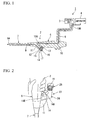
- FIG. 1 shows the configuration of an endoscope system 1 according to the present embodiment.
- FIG 2 shows an operation section 6 of an endoscope of the endoscope system 1 and therearound.
- the endoscope system 1 is provided with: an endoscope 2; a control unit 3; an aspirator 4; an attachment 14 detachably attached to the endoscope 2; and a tissue-collecting apparatus 23 fixed to the endoscope 2 via the attachment 14.
- the endoscope 2 has the operation section 6 operated by the operator; and a flexible and elongated insertion section 7 extending from the distal end of the operation section 6.
- the operation section 6 connected to the control unit 3 via a universal cable 8 has an angle knob and various buttons and switches disposed thereon.
- An operation channel 9 and a suction pipeway 10 are formed in the endoscope 2.
- the operation channel 9 having a distal-end-opening section 9A disposed at the distal end section of the insertion section 7 extends to a lateral section 11 of the operation section 6.
- a proximal end connection port of the operation channel 9 protruding from the lateral section 11 forms a second connection section 12.
- the lateral section 11 has an opening of the distal end section 10A of the suction pipeway 10. This opening is formed close to a second connection section 13 protruding from the lateral section 11.
- a proximal end section 10B of the suction pipeway 10 extending from the operation section 6 and passing through the universal cable 8 is connected to the aspirator 4.
- the second connection section 12 and the second connection section 13 protrude substantially in parallel with each other from the lateral section 11.
- the attachment 14 is attached to each connection section 12 and 13.
- the attachment 14 is formed by a material having a low degree of hardness and a low degree of strength relative to the main body of the endoscope 2, e.g., resin, or elastic material, etc.
- FIG 3 is a perspective view of the attachment 14.
- FIG 4 is a plan view of the attachment 14. As shown in FIGS. 3 and 4 , the first connection pipeway 15 connecting to the operation channel 9 unitarily penetrates from an upper surface 14A to a lower surface 14B of the attachment 14.
- the second connection section 12 can engage with the first connection pipeway 15 at the lower surface 14B.
- An instrument-insertion inlet 16 is formed on the upper surface 14A of the first connection pipeway 15.
- a branch section 17 is formed in the first connection pipeway 15, and a first connection pipeway 18 extends therefrom.
- An opening of the first connection pipeway 18 formed on a lateral surface 14C of the attachment 14 becomes a distal-end-connecting port 19.
- a second connection pipeway 20 extending substantially parallel with the first connection pipeway 18 is provided to the attachment 14.
- An end section of the second connection pipeway 20 has a proximal end connection port 21 formed on the lateral surface 14C of the attachment 14.
- the other end section is connected to a second-coupling pipeway 22 in the attachment 14.
- the second-coupling pipeway 22 has an opening section on only a lateral surface 14C of the attachment 14.
- the opening section has a shape allowing the second connection section 13 connected to the suction pipeway 10 of the endoscope 2 to engage therewith.
- the tissue-collecting apparatus 23 is detachably attached to the distal-end-connecting port 19 and the proximal end connection port 21 of the attachment 14.
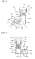
- FIG. 5 is a top plan view of the attachment 14.
- FIGS. 6 to 8 are cross-sectional views taken along the line A-A, the line B-B, and the line C-C of FIG. 5 respectively.
- the tissue-collecting apparatus 23 has a tissue-collecting case 24 and a tissue-collecting filter 25 detachably attached to the tissue-collecting case 24.
- the tissue-collecting case 24 has a casing main unit 26 made of a see-through material, e.g., resin or glass enabling visual observation thereinside.
- the casing main unit 26 is formed by a first main body 27 and a second main body 28 connected to the first main body 27. As shown in FIG. 6 , the casing main unit 26 has a first chamber 29 and a second chamber 30 formed thereinside.
- the first chamber 29 is a space defined by an opening section 27A and a bottom section 27B of the first main body 27.
- the second chamber 30 is a space defined by a ceiling section 28A and a bottom section 28B of the second main body 28.
- the bottom section 27B of the first chamber 29 is substantially flush with the bottom section 28B of the second chamber 30.
- the first chamber 29 communicates with the second chamber 30 via a communication path 31 having an opening at each wall surface of the chamber.
- An opening section 31 A of the communication path 31 formed to the second chamber 30 is disposed above the bottom section 28B of the second chamber 30 by a predetermined distance.
- a distal-end-pipeway 32 and a proximal end pipeway 33 extend parallel with each other from a lateral section of the main unit 26 as shown in FIG. 5 diagonally relative to the casing main unit 26.
- An annular protrusion 32A and an annular protrusion 32B are formed on the outer periphery of the distal-end-pipeway 32.
- the annular protrusion 32B having a diameter greater than that of the annular protrusion 32A is disposed in the vicinity of the casing main unit 26 relative to the annular protrusion 32A.
- An annular protrusion 33A and an annular protrusion 33B are formed on the outer periphery of the proximal end pipeway 33 similarly to the distal-end-pipeway 32.
- the annular protrusion 33B has a diameter greater than that of the annular protrusion 33A.
- the pipeways 32 and 33 communicate with the first chamber 29 and the second chamber 30 at a first communication port 32C and a second communication port 33C
- the first main body 27 has a circular opening section 27A.
- a pair of filter engagement sections 34 are provided to the outer periphery of the opening section 27A.
- a taper surface 27C having an inner diameter reducing toward the bottom section 27B is formed to the opening section 27A of the first main body 27.
- the tissue-collecting filter 25 has a lid section 35 and a filter section 36 extending from the lid section 35 and freely entering the opening section 27A of the first main body 27.
- a pair of fixture sections 37 are provided to the lid section 35. The fixture sections 37 can engage with the filter engagement section 34 of the first main body 27.
- a pair of filter engagement sections 34 each have a pair of taper sections 34D.
- a pair of protrusion sections 34A are provided to face each other in a radial direction with respect to the circumference of the lid section 35 in plan view.
- a pair of insertion ports 34B, and a pair of engagement sections 34C are provided similarly.
- the taper sections 34D are slopes for connecting the insertion port to the engagement section 34C. Rotating the fixture sections 37 of the tissue-collecting filter 25 upon inserting the fixture section 37 into the insertion port 34B causes the fixture sections 37 to move along the taper section 34D, thereby causing the fixture sections 37 to be inserted into the engagement section 34C.
- the fixture sections 37 moving along the taper section 34D causes a seal O ring 38 attached to a lower part of the lid section 35 as shown in FIG 6 to be crushed by the taper surface 27C, thereby sealing the opening section 27A of the first main body 27.
- the porous mesh filter section 36 allows fluid to pass therethrough but not tissue.
- Two tissue-seizing surfaces 36A assembled in one unit are provided to a front side and a back side of the filter section 36.
- the tissue-seizing surfaces 36A are disposed in substantially parallel relative to a line segment joining the pair of fixture sections 37.
- engaging the fixture sections 37 with the filter engagement section 34 of the first main body 27 causes either tissue-seizing surface 36A to be disposed to face the first communication port 32C regularly, thereby, enabling the attachment of the tissue-collecting filter 25 without considering its direction.
- the clearance between the filter section 36 and the first main body 27 is set to prevent tissue from passing therethrough.
- a plate 39 is provided to the tip of the filter section 36.
- the plate 39 does not reduce suction force since a slit 40 is provided to the plate 39 as shown in FIG. 10 .
- attaching the tissue-collecting apparatus 23 to the attachment 14 causes the distal-end-pipeway 32 to be inserted into the first connection pipeway 18.
- the annular protrusion 32A is locked at an annular groove 18A of the first connection pipeway 18, and the annular protrusion 32B abuts the lateral surface 14C. This results in causing the first connection pipeway 15 to communicate with the first chamber 29 of the first main body 27 of the tissue-collecting apparatus 23.
- the filter section 36 of the tissue-collecting filter 25 is inserted into the first chamber 29.
- an operator attaches the tissue-collecting apparatus 23 to the attachment 14 as shown in FIG. 12 .
- the second connection section 12 and the second connection section 13 of the operation section 6 are fit into the first connection pipeway 15 and the second-coupling pipeway 22 of the attachment 14 respectively, and then the attachment 14 is fixed to the endoscope 2.
- This state of attachment 14 is attached to the endoscope 2 so that a lateral surface 14E (first surface) is disposed toward the operation section 6 as shown in FIG. 2 .
- the insertion section 7 in this state is inserted into a patient's body, and a procedure instrument (e.g., incision forceps), not shown in the drawing, is inserted into the instrument-insertion inlet 16 of the attachment 14.
- a procedure instrument e.g., incision forceps
- the procedure instrument upon entering the first connection pipeway 15 of the attachment 14 and the operation channel 9 in the endoscope 2 projects from the distal end section of the insertion section 7.
- the procedure instrument upon incising a target site tissue is removed from the endoscope 2 and the attachment 14.
- the instrument-insertion inlet 16 closing with its restoring force seals the opening thereof.
- Suctioning the incised tissue necessitates actuating the aspirator 4.
- the produced suction force acts on the tissue upon passing through the suction pipeway 10 (including the second-coupling pipeway 22 and the second connection pipeway 20 of the attachment 14), the tissue-collecting apparatus 23, the first connection pipeway 18, and the operation channel 9 (including the first connection pipeway 15).
- the suction pipeway 10 including the second-coupling pipeway 22 and the second connection pipeway 20 of the attachment 14
- the tissue-collecting apparatus 23 including the first connection pipeway 18, and the operation channel 9 (including the first connection pipeway 15).
- the incised tissue not shown in the drawing, and nearby fluid are suctioned into the first chamber 29 of the first main body 27 of the tissue-collecting apparatus 23.
- the tissue is seized by the tissue-seizing surface 36A of the filter section 36 in the first chamber 29.
- the fluid upon passing through the mesh tissue-seizing surface 36A, the slit 40 of the plate 39, the communication path 31, the first chamber 29,
- the tissue-collecting filter 25 is detached from the tissue-collecting case 24, and then the tissue is collected. Stopping the aspirator 4 sometimes causes backflow of a part of the fluid remaining in the suction pipeway 10 back into the tissue-collecting case 24. Fluid 41 flowing back to the second chamber 30 and remaining there hardly moves from the second chamber 30 to the first chamber 29 as shown in FIG. 13B if the operation section 6 is tilted as shown in FIG. 13A . Therefore, the fluid 41 does not spill out, and does not soil the operator and therearound.
- the endoscope system 1 causes the fluid 41 to not be fully suctioned with the incised tissue and remain in the second chamber 30 of the tissue-collecting case 24 to resist moving to the first chamber 29, since the first chamber 29 and the second chamber 30 are formed in the tissue-collecting case 24 and since the communication path 31 having openings on the lateral walls of the two chambers joins the two chambers above the bottom sections of the first chamber 29 and the second chamber 30.
- An aspirator 4 is stopped upon seizing the incised tissue by the tissue-collecting filter 25, and then, the tissue-collecting filter 25 is detached from the tissue-collecting case 24 for taking out the seized tissue. Tilting the operation section 6 while continuing this state of endoscope 2 hardly causes the fluid 41 remaining in the second chamber 30 of the tissue-collecting case 24 to spill out of the tissue-collecting case 24, thereby providing clean operation to the operator and therearound.
Landscapes
- Health & Medical Sciences (AREA)
- Life Sciences & Earth Sciences (AREA)
- Medical Informatics (AREA)
- Engineering & Computer Science (AREA)
- Biomedical Technology (AREA)
- Heart & Thoracic Surgery (AREA)
- Pathology (AREA)
- Molecular Biology (AREA)
- Surgery (AREA)
- Animal Behavior & Ethology (AREA)
- General Health & Medical Sciences (AREA)
- Public Health (AREA)
- Veterinary Medicine (AREA)
- Endoscopes (AREA)
- Surgical Instruments (AREA)
Claims (1)
- Système d'endoscope (1) comprenant:un endoscope (2) ayant une section d'insertion (7) s'étendant à partir d'une section d'opération (6) opérée par un utilisateur jusque dans un corps humain, et un canal d'opération (9) ayant une première section d'extrémité ayant une ouverture à une extrémité distale de la section d'insertion et une deuxième section d'extrémité passant à travers la section d'insertion et ayant une ouverture au niveau de la section d'opération;un appareil de collecte de tissus (23) connecté à un passage de tuyau de connexion se ramifiant à partir d'une section de ramification (17) formée au niveau de la deuxième section d'extrémité dans le canal d'opération, et apte à agripper un tissu rétracté à l'intérieur du canal d'opération;un aspirateur (4) pour produire une force d'aspiration pour aspirer le tissu à l'intérieur du canal d'opération; etun passage de tuyau d'aspiration (10) connectant l'appareil de collecte de tissus à l'aspirateur, dans lequel l'appareil de collecte de tissus a:caractérisé en ce queun boîtier de collecte de tissus (24) ayant une première chambre (29) connectée au passage de tuyau de connexion, une deuxième chambre (30) connectée au passage de tuyau d'aspiration, et une voie de communication (31) prévue au niveau de parois latérales de la première chambre et de la deuxième chambre et faisant que la première chambre communique avec la deuxième chambre, une section d'ouverture de la voie de communication formée sur la deuxième chambre étant disposée au-dessus de la section de fond de la deuxième chambre à une distance prédéterminée,un filtre de collecte de tissus (25) incorporé de façon détachable dans la première chambre,
une section de fond de la deuxième chambre (30) est sensiblement de niveau avec une section de fond de la première chambre (29).
Applications Claiming Priority (1)
| Application Number | Priority Date | Filing Date | Title |
|---|---|---|---|
| US12/047,621 US8382660B2 (en) | 2008-03-13 | 2008-03-13 | Endoscope system having an endoscope and a tissue-collecting apparatus |
Publications (2)
| Publication Number | Publication Date |
|---|---|
| EP2100550A1 EP2100550A1 (fr) | 2009-09-16 |
| EP2100550B1 true EP2100550B1 (fr) | 2011-01-19 |
Family
ID=40566416
Family Applications (1)
| Application Number | Title | Priority Date | Filing Date |
|---|---|---|---|
| EP09003548A Not-in-force EP2100550B1 (fr) | 2008-03-13 | 2009-03-11 | Système d'endoscope |
Country Status (4)
| Country | Link |
|---|---|
| US (1) | US8382660B2 (fr) |
| EP (1) | EP2100550B1 (fr) |
| JP (1) | JP5374132B2 (fr) |
| DE (1) | DE602009000580D1 (fr) |
Cited By (1)
| Publication number | Priority date | Publication date | Assignee | Title |
|---|---|---|---|---|
| CN109044416A (zh) * | 2011-12-16 | 2018-12-21 | 史赛克公司 | 从在医学/外科手术期间产生的流体流提取组织样本的系统 |
Families Citing this family (32)
| Publication number | Priority date | Publication date | Assignee | Title |
|---|---|---|---|---|
| US10278677B2 (en) | 2011-01-28 | 2019-05-07 | The General Hospital Corporation | Apparatus and method for tissue biopsy |
| MX347856B (es) | 2011-01-28 | 2017-05-16 | Massachusetts Gen Hospital | Método y aparato para rejuvenecimiento de la piel. |
| PT2734249T (pt) | 2011-07-21 | 2018-11-13 | Massachusetts Gen Hospital | Aparelho para danificar e remover gordura |
| WO2014130359A1 (fr) | 2013-02-20 | 2014-08-28 | Cytrellis Biosystems, Inc. | Procédés et dispositifs pour le resserrement de la peau |
| BR112016002695B1 (pt) | 2013-08-09 | 2022-09-20 | Cytrellis Biosystems, Inc | Dispositivo com um aparelho ablativo, um aparelho de remoção e um aparelho de posicionamento |
| CN105407812A (zh) * | 2013-11-18 | 2016-03-16 | 奥林巴斯株式会社 | 体液提取用装置及内窥镜系统 |
| US10953143B2 (en) | 2013-12-19 | 2021-03-23 | Cytrellis Biosystems, Inc. | Methods and devices for manipulating subdermal fat |
| KR102670286B1 (ko) | 2014-11-14 | 2024-05-30 | 사이트렐리스 바이오시스템즈, 인크. | 피부 절제를 위한 디바이스 및 방법 |
| CN113368367B (zh) | 2016-02-24 | 2024-03-29 | 禾木(中国)生物工程有限公司 | 柔性增强的神经血管导管 |
| WO2017172920A1 (fr) | 2016-03-29 | 2017-10-05 | Cytrellis Biosystems, Inc. | Dispositifs et méthodes de restructuration cosmétique de la peau |
| EP3515323A4 (fr) | 2016-09-21 | 2020-06-10 | Cytrellis Biosystems, Inc. | Dispositifs et méthodes de restructuration cosmétique de la peau |
| US11696748B2 (en) | 2017-05-02 | 2023-07-11 | Ambu A/S | Set of sampling parts |
| EP3618726A1 (fr) | 2017-05-02 | 2020-03-11 | Ambu A/S | Endoscope |
| EP3530298B1 (fr) | 2018-02-21 | 2023-09-06 | Ambu A/S | Dispositif d'échantillonnage médical |
| EP3636133B1 (fr) | 2018-10-12 | 2024-04-03 | Ambu A/S | Partie de pointe articulée pour un endoscope |
| US11684924B2 (en) * | 2018-12-18 | 2023-06-27 | Huronmed, Llc | Specimen collection device |
| US11766539B2 (en) | 2019-03-29 | 2023-09-26 | Incept, Llc | Enhanced flexibility neurovascular catheter |
| US11318242B2 (en) | 2019-04-12 | 2022-05-03 | Stryker Corporation | Manifold for a medical waste collection system |
| US12350418B2 (en) | 2019-04-12 | 2025-07-08 | Stryker Corporation | Manifold for a medical waste collection system |
| US10471188B1 (en) | 2019-04-12 | 2019-11-12 | Stryker Corporation | Manifold for filtering medical waste being drawn under vacuum into a medical waste collection system |
| USD996640S1 (en) | 2019-11-11 | 2023-08-22 | Stryker Corporation | Specimen collection tray |
| USD930850S1 (en) | 2019-11-20 | 2021-09-14 | Stryker Corporation | Specimen collection tray |
| USD919799S1 (en) | 2019-11-11 | 2021-05-18 | Stryker Corporation | Manifold housing for a medical waste collection device |
| USD956967S1 (en) | 2019-11-11 | 2022-07-05 | Stryker Corporation | Manifold housing for a medical waste collection device |
| USD1031076S1 (en) | 2019-11-20 | 2024-06-11 | Stryker Corporation | Specimen collection tray |
| US11439799B2 (en) | 2019-12-18 | 2022-09-13 | Imperative Care, Inc. | Split dilator aspiration system |
| US12201506B2 (en) | 2019-12-18 | 2025-01-21 | Imperative Care, Inc. | Rotatable thrombus engagement tool |
| CN113384307A (zh) * | 2021-06-29 | 2021-09-14 | 岱川医疗(深圳)有限责任公司 | 用于内窥镜的负压吸引装置及内窥镜系统 |
| EP4233679A1 (fr) | 2022-02-23 | 2023-08-30 | Ambu A/S | Endoscope comprenant une section de flexion ayant des lumens de fil de guidage déplacés |
| CN114795306B (zh) * | 2022-06-27 | 2022-10-18 | 新光维医疗科技(苏州)股份有限公司 | 组织样本采样装置及内窥镜系统 |
| CN116548896B (zh) * | 2023-07-10 | 2023-09-12 | 华伦医疗用品(深圳)有限公司 | 一种可分离式内窥镜 |
| US12171917B1 (en) | 2024-01-08 | 2024-12-24 | Imperative Care, Inc. | Devices for blood capture and reintroduction during aspiration procedure |
Family Cites Families (23)
| Publication number | Priority date | Publication date | Assignee | Title |
|---|---|---|---|---|
| JPS6274804A (ja) | 1985-09-27 | 1987-04-06 | 東京都 | 竪置コンベア式除塵装置 |
| JPS6274804U (fr) | 1985-10-30 | 1987-05-13 | ||
| JPH0347608Y2 (fr) * | 1988-04-23 | 1991-10-11 | ||
| US4870975A (en) * | 1988-07-05 | 1989-10-03 | Scott Cronk | Suction canister assembly for the collection of body fluids and tissue specimens |
| US4957492A (en) * | 1988-12-07 | 1990-09-18 | Cabot Medical Corporation | Apparatus for collecting and handling tissue during uterine evacuation procedure |
| US5363860A (en) * | 1992-10-20 | 1994-11-15 | Nakao Naomi L | Suction trap and associated method |
| US5575293A (en) * | 1995-02-06 | 1996-11-19 | Promex, Inc. | Apparatus for collecting and staging tissue |
| US5624418A (en) * | 1995-10-04 | 1997-04-29 | Shepard; R. David | Collection and separation device |
| US5797742A (en) * | 1996-02-29 | 1998-08-25 | Fraker; Ross M. | Amalgam solids collecting and separating apparatus |
| US6142956A (en) * | 1996-11-25 | 2000-11-07 | Symbiosis Corporation | Proximal actuation handle for a biopsy forceps instrument having irrigation and aspiration capabilities |
| US5971917A (en) * | 1997-02-26 | 1999-10-26 | Fuji Photo Optical Co., Ltd. | Endoscope having washing ports |
| JPH11225951A (ja) * | 1998-02-17 | 1999-08-24 | Olympus Optical Co Ltd | 内視鏡用処置具 |
| JPH11267089A (ja) | 1998-03-24 | 1999-10-05 | Olympus Optical Co Ltd | ポリープ回収用内視鏡システム |
| US6389609B1 (en) * | 1999-08-09 | 2002-05-21 | Stephen J. Andritz | Universal stone catcher urinal system |
| US6428316B1 (en) * | 2001-01-18 | 2002-08-06 | Guillermo P. Rodriquez | Tartar trap |
| JP5073895B2 (ja) * | 2001-09-25 | 2012-11-14 | オリンパス株式会社 | 内視鏡用処置具 |
| US7244236B2 (en) * | 2003-05-16 | 2007-07-17 | M D Technologies Inc. | Specimen trap with strainer |
| US8070756B2 (en) * | 2005-04-15 | 2011-12-06 | U.S. Endoscopy Group, Inc. | Polypectomy device and method of use |
| JP4657021B2 (ja) * | 2005-06-16 | 2011-03-23 | オリンパスメディカルシステムズ株式会社 | 組織捕獲装置、内視鏡用処置具及び内視鏡 |
| JP4746359B2 (ja) * | 2005-06-20 | 2011-08-10 | オリンパスメディカルシステムズ株式会社 | 内視鏡用処置具 |
| JP2007202360A (ja) | 2006-01-30 | 2007-08-09 | Nissan Motor Co Ltd | 電動機の絶縁性能回復装置 |
| JP4932266B2 (ja) | 2006-01-31 | 2012-05-16 | オリンパスメディカルシステムズ株式会社 | 内視鏡システム |
| JP2007209764A (ja) | 2006-02-10 | 2007-08-23 | Us Endoscopy Group Inc | ポリープトラップ |
-
2008
- 2008-03-13 US US12/047,621 patent/US8382660B2/en not_active Expired - Fee Related
- 2008-12-11 JP JP2008315798A patent/JP5374132B2/ja not_active Expired - Fee Related
-
2009
- 2009-03-11 EP EP09003548A patent/EP2100550B1/fr not_active Not-in-force
- 2009-03-11 DE DE602009000580T patent/DE602009000580D1/de active Active
Cited By (2)
| Publication number | Priority date | Publication date | Assignee | Title |
|---|---|---|---|---|
| CN109044416A (zh) * | 2011-12-16 | 2018-12-21 | 史赛克公司 | 从在医学/外科手术期间产生的流体流提取组织样本的系统 |
| EP3730061B1 (fr) * | 2011-12-16 | 2024-04-10 | Stryker Corporation | Cassette configurée pour être utilisée avec un système de collecte de déchets médicaux |
Also Published As
| Publication number | Publication date |
|---|---|
| JP5374132B2 (ja) | 2013-12-25 |
| EP2100550A1 (fr) | 2009-09-16 |
| DE602009000580D1 (de) | 2011-03-03 |
| US8382660B2 (en) | 2013-02-26 |
| US20090234192A1 (en) | 2009-09-17 |
| JP2009219858A (ja) | 2009-10-01 |
Similar Documents
| Publication | Publication Date | Title |
|---|---|---|
| EP2100550B1 (fr) | Système d'endoscope | |
| AU2020203442B2 (en) | Cassette for use with a medical waste collection system | |
| US8070756B2 (en) | Polypectomy device and method of use | |
| US8262565B2 (en) | Endoscope system | |
| US8414478B2 (en) | Endoscopic aspiration device | |
| EP2145578B1 (fr) | Dispositifs pour conserver la visibilité et fournir une irrigation et/ou une aspiration pendant des interventions chirurgicales | |
| EP3530298B1 (fr) | Dispositif d'échantillonnage médical | |
| KR20140079470A (ko) | 광학 투관침 시스템 | |
| JP4746359B2 (ja) | 内視鏡用処置具 | |
| US5605537A (en) | Endoscopic device | |
| US11849969B2 (en) | Cannula with smoke evacuation housing | |
| EP0875256A1 (fr) | Canule d'irrigation et d'aspiration | |
| CN113288019A (zh) | 一种实时清洁内窥镜镜头的接入组件及其使用方法 | |
| CN116636908A (zh) | 一种用于人体病变组织的清创装置 | |
| WO2007129321A2 (fr) | instrument Électrochirurgical avec aspiration, irrigation et moyen de collecte du sang | |
| JP2011212450A (ja) | 内視鏡用処置具 | |
| US8550743B2 (en) | Sliding lock device | |
| US5310406A (en) | Endoscopic aspirator surgical instrument | |
| JPH11267089A (ja) | ポリープ回収用内視鏡システム | |
| JP2937101B2 (ja) | 内視鏡装置 | |
| KR20220040916A (ko) | 흡인세척관 및 이를 포함하는 흡인세척장치 | |
| CN114271905B (zh) | 多功能穿刺器、手术系统及其使用方法 | |
| CN116211222A (zh) | 一种内窥镜的引导装置及内窥镜 | |
| KR20200071506A (ko) | 복강경 수술 중 발생하는 유해가스 여과를 위한 트로카 장착 필터 구조체 | |
| US12582761B2 (en) | Surgical device comprising a rod having a deformable sleeve at its distal end surrounding said rod |
Legal Events
| Date | Code | Title | Description |
|---|---|---|---|
| PUAI | Public reference made under article 153(3) epc to a published international application that has entered the european phase |
Free format text: ORIGINAL CODE: 0009012 |
|
| AK | Designated contracting states |
Kind code of ref document: A1 Designated state(s): AT BE BG CH CY CZ DE DK EE ES FI FR GB GR HR HU IE IS IT LI LT LU LV MC MK MT NL NO PL PT RO SE SI SK TR |
|
| AX | Request for extension of the european patent |
Extension state: AL BA RS |
|
| RAP1 | Party data changed (applicant data changed or rights of an application transferred) |
Owner name: OLYMPUS MEDICAL SYSTEMS CORP. |
|
| 17P | Request for examination filed |
Effective date: 20100118 |
|
| 17Q | First examination report despatched |
Effective date: 20100216 |
|
| AKX | Designation fees paid |
Designated state(s): DE FR GB IE |
|
| GRAP | Despatch of communication of intention to grant a patent |
Free format text: ORIGINAL CODE: EPIDOSNIGR1 |
|
| GRAS | Grant fee paid |
Free format text: ORIGINAL CODE: EPIDOSNIGR3 |
|
| GRAA | (expected) grant |
Free format text: ORIGINAL CODE: 0009210 |
|
| AK | Designated contracting states |
Kind code of ref document: B1 Designated state(s): DE FR GB IE |
|
| REG | Reference to a national code |
Ref country code: GB Ref legal event code: FG4D |
|
| REG | Reference to a national code |
Ref country code: IE Ref legal event code: FG4D |
|
| REF | Corresponds to: |
Ref document number: 602009000580 Country of ref document: DE Date of ref document: 20110303 Kind code of ref document: P |
|
| REG | Reference to a national code |
Ref country code: DE Ref legal event code: R096 Ref document number: 602009000580 Country of ref document: DE Effective date: 20110303 |
|
| PLBE | No opposition filed within time limit |
Free format text: ORIGINAL CODE: 0009261 |
|
| STAA | Information on the status of an ep patent application or granted ep patent |
Free format text: STATUS: NO OPPOSITION FILED WITHIN TIME LIMIT |
|
| 26N | No opposition filed |
Effective date: 20111020 |
|
| REG | Reference to a national code |
Ref country code: DE Ref legal event code: R097 Ref document number: 602009000580 Country of ref document: DE Effective date: 20111020 |
|
| PGFP | Annual fee paid to national office [announced via postgrant information from national office to epo] |
Ref country code: IE Payment date: 20140311 Year of fee payment: 6 |
|
| REG | Reference to a national code |
Ref country code: FR Ref legal event code: PLFP Year of fee payment: 7 |
|
| PGFP | Annual fee paid to national office [announced via postgrant information from national office to epo] |
Ref country code: FR Payment date: 20150309 Year of fee payment: 7 Ref country code: GB Payment date: 20150311 Year of fee payment: 7 |
|
| REG | Reference to a national code |
Ref country code: DE Ref legal event code: R082 Ref document number: 602009000580 Country of ref document: DE Representative=s name: WUESTHOFF & WUESTHOFF, PATENTANWAELTE PARTG MB, DE Ref country code: DE Ref legal event code: R081 Ref document number: 602009000580 Country of ref document: DE Owner name: OLYMPUS CORPORATION, JP Free format text: FORMER OWNER: OLYMPUS MEDICAL SYSTEMS CORP., TOKYO, JP |
|
| REG | Reference to a national code |
Ref country code: IE Ref legal event code: MM4A |
|
| PG25 | Lapsed in a contracting state [announced via postgrant information from national office to epo] |
Ref country code: IE Free format text: LAPSE BECAUSE OF NON-PAYMENT OF DUE FEES Effective date: 20150311 |
|
| GBPC | Gb: european patent ceased through non-payment of renewal fee |
Effective date: 20160311 |
|
| REG | Reference to a national code |
Ref country code: FR Ref legal event code: ST Effective date: 20161130 |
|
| PG25 | Lapsed in a contracting state [announced via postgrant information from national office to epo] |
Ref country code: GB Free format text: LAPSE BECAUSE OF NON-PAYMENT OF DUE FEES Effective date: 20160311 Ref country code: FR Free format text: LAPSE BECAUSE OF NON-PAYMENT OF DUE FEES Effective date: 20160331 |
|
| PGFP | Annual fee paid to national office [announced via postgrant information from national office to epo] |
Ref country code: DE Payment date: 20190321 Year of fee payment: 11 |
|
| REG | Reference to a national code |
Ref country code: DE Ref legal event code: R119 Ref document number: 602009000580 Country of ref document: DE |
|
| PG25 | Lapsed in a contracting state [announced via postgrant information from national office to epo] |
Ref country code: DE Free format text: LAPSE BECAUSE OF NON-PAYMENT OF DUE FEES Effective date: 20201001 |