EP2100833A1 - Vorrichtung zur individuellen Förderung von länglichen Artikeln - Google Patents
Vorrichtung zur individuellen Förderung von länglichen Artikeln Download PDFInfo
- Publication number
- EP2100833A1 EP2100833A1 EP09154112A EP09154112A EP2100833A1 EP 2100833 A1 EP2100833 A1 EP 2100833A1 EP 09154112 A EP09154112 A EP 09154112A EP 09154112 A EP09154112 A EP 09154112A EP 2100833 A1 EP2100833 A1 EP 2100833A1
- Authority
- EP
- European Patent Office
- Prior art keywords
- articles
- tract
- elongate
- conveyor belt
- elongate articles
- Prior art date
- Legal status (The legal status is an assumption and is not a legal conclusion. Google has not performed a legal analysis and makes no representation as to the accuracy of the status listed.)
- Granted
Links
Images


Classifications
-
- B—PERFORMING OPERATIONS; TRANSPORTING
- B65—CONVEYING; PACKING; STORING; HANDLING THIN OR FILAMENTARY MATERIAL
- B65G—TRANSPORT OR STORAGE DEVICES, e.g. CONVEYORS FOR LOADING OR TIPPING, SHOP CONVEYOR SYSTEMS OR PNEUMATIC TUBE CONVEYORS
- B65G47/00—Article or material-handling devices associated with conveyors; Methods employing such devices
- B65G47/02—Devices for feeding articles or materials to conveyors
- B65G47/04—Devices for feeding articles or materials to conveyors for feeding articles
- B65G47/12—Devices for feeding articles or materials to conveyors for feeding articles from disorderly-arranged article piles or from loose assemblages of articles
- B65G47/14—Devices for feeding articles or materials to conveyors for feeding articles from disorderly-arranged article piles or from loose assemblages of articles arranging or orientating the articles by mechanical or pneumatic means during feeding
- B65G47/1407—Devices for feeding articles or materials to conveyors for feeding articles from disorderly-arranged article piles or from loose assemblages of articles arranging or orientating the articles by mechanical or pneumatic means during feeding the articles being fed from a container, e.g. a bowl
- B65G47/1442—Devices for feeding articles or materials to conveyors for feeding articles from disorderly-arranged article piles or from loose assemblages of articles arranging or orientating the articles by mechanical or pneumatic means during feeding the articles being fed from a container, e.g. a bowl by means of movement of the bottom or a part of the wall of the container
- B65G47/1471—Movement in one direction, substantially outwards
Definitions
- the invention relates to the technical sector of packing of articles, with special reference to those devices which collect the articles from a storage container in which they are loosely arranged, and feeds them to a station in which gripping organs are located which remove them individually and transfer them, for example, to an input line of an automatic machine.
- a known solution for collection of elongate articles comprises a first conveyor the initial part of which is immersed in the pile of loose articles and develops in an upwards direction; the first conveyor is constituted by a sort of escalator in which each step is activated with alternating ascending and descending motion, in suitable phase-relation to the others; when two consecutive steps are in the respective higher and lower position, they are aligned and the article borne on the lower step transfers by force of gravity to the upper step, thanks to a special inclination of the "tread" of the steps; the articles, therefore, progressively ascend all the steps and are unloaded onto a second conveyor which develops horizontally and perpendicularly with respect to the output of the articles from the first conveyor.
- Means for detecting the position of the articles are located in the second conveyor and downstream of the means for detecting are located the gripping organs of the single articles.
- a further drawback of the known solution relates to the difficulty of changing format for the first conveyor, due to the dimensional constraint between the depth of the steps and the transversal dimension of the articles.
- the aim of the present invention is thus to realise a device conformed expressly for individually conveying elongate articles towards a downstream position, such as to make sure the articles remain in the correct predetermined position and orientation.
- a further aim of the invention consists in providing a device which can over a defined period of time feed a higher-than-required number of articles to the packing station.
- a further aim of the invention relates to the desire to provide a device conformed in such a way as to collect the articles supplied in excess at the output such that they can be returned to the work cycle at the input of the device.
- a further aim of the invention is to provide a device in which the replacement of the transversal separator elements, which relate one-by-one to different formats, is particularly easy, while also limiting the number required thereof.
- a still further aim of the invention regards the intention to realise a device of simple construction and certain reliability.
- the device 1 is destined to deal with elongate articles 2 which might have two identical ends or different ends, such as for example syringes, tubes for medicine and the like, and a constant section or a section which is variable from an end to another.
- the condition considered is one in which the two ends of the articles 2 are different, with the need, therefore, to guarantee a precise orientation thereof, at the output of the device 1.
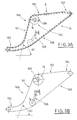
- the device 1 comprises a main body 10 in which a hopper 11 is realised ( figures 1 and 2 ) destined to contain the elongate articles 2 ( figures 1 and 5 ).
- the hopper 11 is open at a lower mouth thereof 11A and lies above means for picking-up 12, which support the pile of the elongate articles 2.
- the means for picking-up 12 are constituted by a conveyor belt, designed to be step-activated to extract batches of the articles 2, directing them towards a slit 110 afforded laterally in the hopper 11, as will be better described herein below.
- the main body 10 supports the drive roller 13 and the driven rollers 14, 15 on which a conveyor belt 16 is ring-wound, in an outwards-facing surface of which a plurality of transversal seatings 17 of specific dimensions are delimited ( figure 1 ).
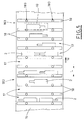
- Each seating 17 is identified in a space between two consecutive laths 18, arranged transversally of the belt 16 and removably associated to the belt by means of a rapid attachment 180 ( figures 1 and 5 ).
- the laths 18 can exhibit a section of various forms and sizes, according to the article 2 to which they are destined for use.
- each transversal seating 17, in a parallel direction to the development of the belt 16 is such as to enable the seating 17 to house one alone of the elongate articles 2 along the direction; this is due to the fact that the size of the width L is less than double the maximum width of the elongate articles 2 ( figure 5 ).
- the means for rapid attachment 180 are constituted by at least two metal pins 181, parallel to one another and made solid to a lower side of each lath 18, destined to insert in complementarily-shaped niches 182 afforded in the conveyor belt 16; each pair of niches 182 is distanced from adjacent niches according to the development direction of the belt 16, with a constant step.
- each niche 182 there is a magnet 183 which exerts, on the relative pin 181, a predetermined force of attraction, sufficient, together with the force exerted on the other pin 181 by the relative magnet 183, to keep the corresponding lath 18 solidly anchored to the belt 16 ( figures 4A, 4B ).
- Two consecutive branches 16 are defined in the conveyor belt, respectively the upper operating branch 16A and the lower return branch 16B ( figures 1 and 3 ), the first of which comprises, according to the advancement direction W:
- Adjustment organs 164 are associated to the conveyor belt 16, which organs 164 vary the inclination of the ascending tract 161 from a minimum inclination ⁇ 1 to a maximum inclination ⁇ 2, according to the shape, the size and the type of elongate articles 2 which are treated, with the aim of optimising the selection of the articles 2, ensuring that the transversal seatings 17 are as regularly filled as possible.
- the adjustment organs 164 in a possible embodiment thereof illustrated schematically in figures 3A and 3B , comprise slotted flanges 165 for supporting the return roller 15 interposed between the ascending tract 161 and the intermediate tract 162, and stretcher means 166 for keeping the conveyor belt 16 taut.
- the flanges 165 are fixed to the main body 10 such that the development direction of the relative slots is advantageously parallel to the inclination of the intermediate tract 162; for this reason, the displacement of the return pulley 15 causes a variation in the inclination of the ascending tract 161 from a maximum ⁇ 2 ( figure 3A ) to a minimum ⁇ 1 ( figure 3B ), maintaining however the inclination of the intermediate tract 162 intact.
- Sensor organs 20 are present in the supply station S1, which sensor organs 20 detect a minimum load level of elongate objects 2, which have exited from the slot 110 and which have fallen onto the initial tract 160 of the belt 16; the sensor organs 20, on detecting an insufficient quantity of articles 2, provide the signal for enabling the intermittent activating of the conveyor belt 12, such that it extracts a further batch of articles 2.
- Optical detecting organs 30 are located above the intermediate tract 162, for example a television camera ( figure 1 ) for monitoring the transversal seatings 17 in transit, in order to detect either the presence or absence in each transversal seating 17 of elongate articles 2, and should there be any present, the number, position and orientation thereof.
- the seatings 17 which arrive in the intermediate tract 162 and the successive final tract 163 can contain one or two elongate articles 2, with a random position and orientation, or they can be empty.
- robotic manipulating organs 40 ( figure 1 and the insert of figure 5 ), controlled by the optical detection organs 30, which manipulating organs 40 grip at least one of the elongate articles 2 from each of the arriving full transversal seatings 17 on the basis of coordinates provided by the optical detecting organs 30, in order to transfer the at least one elongate article 2 into an output position downstream (not illustrated) with predetermined orientation.
- the device 1 finally comprises means 50 for collecting elongate articles 2 not collected by the robotic manipulating organs 40 and unloaded from the conveyor belt 16 beyond the final tract 163 of the relative operating branch 16A.
- the means for collecting 50 comprise a chute 51 which guides the unloaded elongate articles 2 from the conveyor belt 16 towards a return conveyor 52 for returning the elongate 2 to the inside of the hopper 11 ( figures 1 and 2 ).
- the return conveyor 52 is not present and is replaced by a collection container which an operative periodically empties back into the hopper 11.
- the system of magnetic anchoring of the laths to the conveyor belt is of particular interest, as it guarantees an easy and rapid substitution thereof when container format is to be changed; in this regard it is of note that the laths are also the only element relating to a precise format present in the device.
- the device of the invention is realisable with contained costs, thanks to the intrinsic constructional simplicity of its parts and the fact that some complex components (television camera and robot) are normally available commercially and are thus available at competitive costs, as well as being entirely reliable.
Landscapes
- Engineering & Computer Science (AREA)
- Mechanical Engineering (AREA)
- Feeding Of Articles To Conveyors (AREA)
- Attitude Control For Articles On Conveyors (AREA)
- Control Of Conveyors (AREA)
- Control And Other Processes For Unpacking Of Materials (AREA)
- Lubricants (AREA)
- Transition And Organic Metals Composition Catalysts For Addition Polymerization (AREA)
- Filling Or Emptying Of Bunkers, Hoppers, And Tanks (AREA)
- Specific Conveyance Elements (AREA)
Applications Claiming Priority (1)
| Application Number | Priority Date | Filing Date | Title |
|---|---|---|---|
| IT000166A ITBO20080166A1 (it) | 2008-03-14 | 2008-03-14 | Dispositivo per il convogliamento singolarizzato di articoli oblunghi |
Publications (2)
| Publication Number | Publication Date |
|---|---|
| EP2100833A1 true EP2100833A1 (de) | 2009-09-16 |
| EP2100833B1 EP2100833B1 (de) | 2012-05-02 |
Family
ID=40292652
Family Applications (1)
| Application Number | Title | Priority Date | Filing Date |
|---|---|---|---|
| EP09154112A Active EP2100833B1 (de) | 2008-03-14 | 2009-03-02 | Vorrichtung zur individuellen Förderung von länglichen Artikeln |
Country Status (4)
| Country | Link |
|---|---|
| US (1) | US7743904B2 (de) |
| EP (1) | EP2100833B1 (de) |
| ES (1) | ES2386621T3 (de) |
| IT (1) | ITBO20080166A1 (de) |
Cited By (3)
| Publication number | Priority date | Publication date | Assignee | Title |
|---|---|---|---|---|
| ITBO20110017A1 (it) * | 2011-01-21 | 2012-07-22 | Simoni S R L | Macchina e metodo per orientare oggetti in una direzione predeterminata |
| FR2997927A1 (fr) * | 2012-11-13 | 2014-05-16 | Unista | Machine de distribution d'objets avec alimentation en vrac |
| CN110615275A (zh) * | 2019-09-19 | 2019-12-27 | 基点维科(成都)医疗机器人技术有限公司 | 一种挑管装置 |
Families Citing this family (11)
| Publication number | Priority date | Publication date | Assignee | Title |
|---|---|---|---|---|
| DE102010042333A1 (de) * | 2010-10-12 | 2012-04-12 | Krones Aktiengesellschaft | Vorrichtung zum Ausrichten von Gegenständen |
| JP5656625B2 (ja) * | 2010-12-29 | 2015-01-21 | シスメックス株式会社 | 試料分析装置 |
| CN102765591B (zh) * | 2012-08-07 | 2014-04-16 | 江西科伦医疗器械制造有限公司 | 一次性使用无菌注射器自动摆料系统 |
| ITBO20130162A1 (it) * | 2013-04-12 | 2014-10-13 | Marchesini Group Spa | Metodo e sistema per sincronizzare una stazione di lavorazione di una macchina blisteratrice con l'avanzamento di un nastro blister |
| ES2534423B1 (es) * | 2013-10-21 | 2016-01-26 | Tomás MULET VALLES | Máquina suministradora de envases |
| CA2927205A1 (en) * | 2015-04-13 | 2016-10-13 | Carbotech International | U-shaped board unscrambler |
| US10370196B2 (en) * | 2017-02-01 | 2019-08-06 | J.E. Grote Co., Inc. | Food product separating and aligning apparatus |
| CN108249124A (zh) * | 2018-01-15 | 2018-07-06 | 马鞍山邦德医疗器械有限公司 | 一种细长工件的精准输送装置及其输送方法 |
| IT202000006958A1 (it) * | 2020-04-02 | 2021-10-02 | Sacmi Beverage S P A | Dispositivo per l'orientamento e l'alimentazione di tappi. |
| DE102021129997A1 (de) * | 2021-11-17 | 2023-05-17 | HTI Automation GmbH | Vereinzelungsvorrichtung |
| DE102022104739A1 (de) * | 2022-02-28 | 2023-08-31 | TRUMPF Werkzeugmaschinen SE + Co. KG | Vereinzelungsvorrichtung für rohr- oder stangenförmige Werkstücke |
Citations (4)
| Publication number | Priority date | Publication date | Assignee | Title |
|---|---|---|---|---|
| FR2571705A1 (fr) * | 1984-10-12 | 1986-04-18 | Applic Vibration | Procede pour distribuer des coupelles et moyens de mise en oeuvre |
| DE3718481A1 (de) * | 1987-06-02 | 1988-12-15 | Sortimat Creuz & Co Gmbh | Vorrichtung zum foerdern und zufuehren von zylinderfoermigen gegenstaenden |
| US5236077A (en) * | 1992-10-02 | 1993-08-17 | Hoppmann Corporation | Linear feeder |
| DE10133805A1 (de) * | 2001-07-11 | 2003-01-30 | Braun Gmbh | Einrichtung zum Zuführen von Bauteilen zu einer Montagestation |
Family Cites Families (7)
| Publication number | Priority date | Publication date | Assignee | Title |
|---|---|---|---|---|
| US3392815A (en) * | 1966-07-14 | 1968-07-16 | Unscrambler Corp Of New Jersey | Unscrambling and orienting apparatus |
| US3658167A (en) * | 1970-06-11 | 1972-04-25 | Frank Zabroski | Method of and device for conveying and arrangeing empty receptacles, such as bottles or jars |
| US3624773A (en) * | 1970-06-17 | 1971-11-30 | Pace Packaging Corp | Continuously moving apparatus for uprighting bottles |
| US3835985A (en) * | 1972-06-19 | 1974-09-17 | Wiebe Mfg Inc | Vacuum assist can unscrambler |
| IT1179315B (it) * | 1984-04-19 | 1987-09-16 | Acma Spa | Apparecchiatura per disporre orizzonalmente ed in sequenza recipienti del tipo delle bottiglie flaconi e simili |
| US6401906B1 (en) * | 2001-01-22 | 2002-06-11 | Timothy G. Franz | S-shaped board unscrambler |
| ES2223247B1 (es) * | 2002-11-22 | 2006-04-16 | Tomas Mulet Valles | Maquina alimentadora-dispensadora de recipientes y articulos alargados en general. |
-
2008
- 2008-03-14 IT IT000166A patent/ITBO20080166A1/it unknown
-
2009
- 2009-02-24 US US12/391,300 patent/US7743904B2/en active Active
- 2009-03-02 ES ES09154112T patent/ES2386621T3/es active Active
- 2009-03-02 EP EP09154112A patent/EP2100833B1/de active Active
Patent Citations (4)
| Publication number | Priority date | Publication date | Assignee | Title |
|---|---|---|---|---|
| FR2571705A1 (fr) * | 1984-10-12 | 1986-04-18 | Applic Vibration | Procede pour distribuer des coupelles et moyens de mise en oeuvre |
| DE3718481A1 (de) * | 1987-06-02 | 1988-12-15 | Sortimat Creuz & Co Gmbh | Vorrichtung zum foerdern und zufuehren von zylinderfoermigen gegenstaenden |
| US5236077A (en) * | 1992-10-02 | 1993-08-17 | Hoppmann Corporation | Linear feeder |
| DE10133805A1 (de) * | 2001-07-11 | 2003-01-30 | Braun Gmbh | Einrichtung zum Zuführen von Bauteilen zu einer Montagestation |
Cited By (5)
| Publication number | Priority date | Publication date | Assignee | Title |
|---|---|---|---|---|
| ITBO20110017A1 (it) * | 2011-01-21 | 2012-07-22 | Simoni S R L | Macchina e metodo per orientare oggetti in una direzione predeterminata |
| FR2997927A1 (fr) * | 2012-11-13 | 2014-05-16 | Unista | Machine de distribution d'objets avec alimentation en vrac |
| FR2997928A1 (fr) * | 2012-11-13 | 2014-05-16 | Unista | Machine de distribution d'objets avec alimentation en vrac |
| WO2014076409A3 (fr) * | 2012-11-13 | 2014-07-31 | Unista | Machine de distribution d'objets avec alimentation en vrac |
| CN110615275A (zh) * | 2019-09-19 | 2019-12-27 | 基点维科(成都)医疗机器人技术有限公司 | 一种挑管装置 |
Also Published As
| Publication number | Publication date |
|---|---|
| US7743904B2 (en) | 2010-06-29 |
| ES2386621T3 (es) | 2012-08-23 |
| ITBO20080166A1 (it) | 2009-09-15 |
| EP2100833B1 (de) | 2012-05-02 |
| US20090229951A1 (en) | 2009-09-17 |
Similar Documents
| Publication | Publication Date | Title |
|---|---|---|
| EP2100833B1 (de) | Vorrichtung zur individuellen Förderung von länglichen Artikeln | |
| US10232410B2 (en) | Induction conveyor | |
| CN110997529B (zh) | 物品分类和分拣系统 | |
| US8011492B2 (en) | Device for the accumulation and release of products, especially products arranged in ranks feeding packaging lines for such products | |
| CA2757936C (en) | Device for the return of empties, in particular plastic bottles and metal cans | |
| WO2013116801A1 (en) | Sortation systems and related methods | |
| JPS62182011A (ja) | 包装用装置の改良及びその方法 | |
| US20090199512A1 (en) | Filling Unit | |
| US7641040B2 (en) | Textile separating apparatus | |
| US20160229642A1 (en) | Machine for supplying containers | |
| US6622848B1 (en) | Pouch reverse shingling system | |
| JP2017006826A (ja) | 果菜自動選別方法と、果菜自動選別装置と、パック詰め装置と、果菜選別パック詰め装置と、果菜キャリア | |
| US5480278A (en) | Automatic stacker apparatus and method | |
| JP3839896B2 (ja) | 農産物の選別包装装置 | |
| ES3036605T3 (en) | System for cultivating and harvesting mushrooms | |
| WO2025051487A1 (en) | Machine for filling containers of horticultural products | |
| EP3265410A1 (de) | Tablettstapelspender | |
| JP2022164151A (ja) | 物品搬送システム、及び、供給装置 | |
| JP3668576B2 (ja) | 農産物の選別包装装置 | |
| KR20140015317A (ko) | 알 포장 장치 및 알 포장 방법 | |
| JP2548840B2 (ja) | 作物の選別用搬送装置 | |
| JP5190188B2 (ja) | 農畜産物の分配整列装置 | |
| JP2684503B2 (ja) | 物品の荷受方法及び装置 | |
| JP2582960B2 (ja) | 作物の選別用搬送装置 | |
| JP2000296912A (ja) | 農産物の選別包装装置 |
Legal Events
| Date | Code | Title | Description |
|---|---|---|---|
| PUAI | Public reference made under article 153(3) epc to a published international application that has entered the european phase |
Free format text: ORIGINAL CODE: 0009012 |
|
| AK | Designated contracting states |
Kind code of ref document: A1 Designated state(s): AT BE BG CH CY CZ DE DK EE ES FI FR GB GR HR HU IE IS IT LI LT LU LV MC MK MT NL NO PL PT RO SE SI SK TR |
|
| AX | Request for extension of the european patent |
Extension state: AL BA RS |
|
| 17P | Request for examination filed |
Effective date: 20091113 |
|
| AKX | Designation fees paid |
Designated state(s): DE ES FR IT |
|
| GRAP | Despatch of communication of intention to grant a patent |
Free format text: ORIGINAL CODE: EPIDOSNIGR1 |
|
| GRAS | Grant fee paid |
Free format text: ORIGINAL CODE: EPIDOSNIGR3 |
|
| GRAA | (expected) grant |
Free format text: ORIGINAL CODE: 0009210 |
|
| AK | Designated contracting states |
Kind code of ref document: B1 Designated state(s): DE ES FR IT |
|
| REG | Reference to a national code |
Ref country code: DE Ref legal event code: R096 Ref document number: 602009006693 Country of ref document: DE Effective date: 20120705 |
|
| REG | Reference to a national code |
Ref country code: ES Ref legal event code: FG2A Ref document number: 2386621 Country of ref document: ES Kind code of ref document: T3 Effective date: 20120823 |
|
| PLBE | No opposition filed within time limit |
Free format text: ORIGINAL CODE: 0009261 |
|
| STAA | Information on the status of an ep patent application or granted ep patent |
Free format text: STATUS: NO OPPOSITION FILED WITHIN TIME LIMIT |
|
| 26N | No opposition filed |
Effective date: 20130205 |
|
| REG | Reference to a national code |
Ref country code: DE Ref legal event code: R097 Ref document number: 602009006693 Country of ref document: DE Effective date: 20130205 |
|
| REG | Reference to a national code |
Ref country code: FR Ref legal event code: PLFP Year of fee payment: 8 |
|
| REG | Reference to a national code |
Ref country code: FR Ref legal event code: PLFP Year of fee payment: 9 |
|
| REG | Reference to a national code |
Ref country code: FR Ref legal event code: PLFP Year of fee payment: 10 |
|
| P01 | Opt-out of the competence of the unified patent court (upc) registered |
Free format text: CASE NUMBER: APP_49833/2024 Effective date: 20240903 |
|
| PGFP | Annual fee paid to national office [announced via postgrant information from national office to epo] |
Ref country code: IT Payment date: 20250325 Year of fee payment: 17 |
|
| PGFP | Annual fee paid to national office [announced via postgrant information from national office to epo] |
Ref country code: DE Payment date: 20250404 Year of fee payment: 17 |
|
| PGFP | Annual fee paid to national office [announced via postgrant information from national office to epo] |
Ref country code: ES Payment date: 20250403 Year of fee payment: 17 |
|
| PGFP | Annual fee paid to national office [announced via postgrant information from national office to epo] |
Ref country code: FR Payment date: 20260317 Year of fee payment: 18 |