EP2101076A2 - Bremsscheibe und Fahrzeug - Google Patents
Bremsscheibe und Fahrzeug Download PDFInfo
- Publication number
- EP2101076A2 EP2101076A2 EP09250592A EP09250592A EP2101076A2 EP 2101076 A2 EP2101076 A2 EP 2101076A2 EP 09250592 A EP09250592 A EP 09250592A EP 09250592 A EP09250592 A EP 09250592A EP 2101076 A2 EP2101076 A2 EP 2101076A2
- Authority
- EP
- European Patent Office
- Prior art keywords
- hub
- portions
- coupling
- brake disk
- arm portions
- Prior art date
- Legal status (The legal status is an assumption and is not a legal conclusion. Google has not performed a legal analysis and makes no representation as to the accuracy of the status listed.)
- Granted
Links
- 230000008878 coupling Effects 0.000 claims abstract description 124
- 238000010168 coupling process Methods 0.000 claims abstract description 124
- 238000005859 coupling reaction Methods 0.000 claims abstract description 124
- 230000002093 peripheral effect Effects 0.000 claims abstract description 55
- 230000000694 effects Effects 0.000 description 9
- 238000005452 bending Methods 0.000 description 6
- XEEYBQQBJWHFJM-UHFFFAOYSA-N Iron Chemical compound [Fe] XEEYBQQBJWHFJM-UHFFFAOYSA-N 0.000 description 2
- 230000005489 elastic deformation Effects 0.000 description 2
- 229910052782 aluminium Inorganic materials 0.000 description 1
- XAGFODPZIPBFFR-UHFFFAOYSA-N aluminium Chemical compound [Al] XAGFODPZIPBFFR-UHFFFAOYSA-N 0.000 description 1
- 230000003247 decreasing effect Effects 0.000 description 1
- 229910052742 iron Inorganic materials 0.000 description 1
- 229910052751 metal Inorganic materials 0.000 description 1
- 239000002184 metal Substances 0.000 description 1
- XLYOFNOQVPJJNP-UHFFFAOYSA-N water Substances O XLYOFNOQVPJJNP-UHFFFAOYSA-N 0.000 description 1
Images




Classifications
-
- F—MECHANICAL ENGINEERING; LIGHTING; HEATING; WEAPONS; BLASTING
- F16—ENGINEERING ELEMENTS AND UNITS; GENERAL MEASURES FOR PRODUCING AND MAINTAINING EFFECTIVE FUNCTIONING OF MACHINES OR INSTALLATIONS; THERMAL INSULATION IN GENERAL
- F16D—COUPLINGS FOR TRANSMITTING ROTATION; CLUTCHES; BRAKES
- F16D65/00—Parts or details
- F16D65/02—Braking members; Mounting thereof
- F16D65/12—Discs; Drums for disc brakes
- F16D65/123—Discs; Drums for disc brakes comprising an annular disc secured to a hub member; Discs characterised by means for mounting
-
- F—MECHANICAL ENGINEERING; LIGHTING; HEATING; WEAPONS; BLASTING
- F16—ENGINEERING ELEMENTS AND UNITS; GENERAL MEASURES FOR PRODUCING AND MAINTAINING EFFECTIVE FUNCTIONING OF MACHINES OR INSTALLATIONS; THERMAL INSULATION IN GENERAL
- F16D—COUPLINGS FOR TRANSMITTING ROTATION; CLUTCHES; BRAKES
- F16D65/00—Parts or details
- F16D65/0006—Noise or vibration control
-
- F—MECHANICAL ENGINEERING; LIGHTING; HEATING; WEAPONS; BLASTING
- F16—ENGINEERING ELEMENTS AND UNITS; GENERAL MEASURES FOR PRODUCING AND MAINTAINING EFFECTIVE FUNCTIONING OF MACHINES OR INSTALLATIONS; THERMAL INSULATION IN GENERAL
- F16D—COUPLINGS FOR TRANSMITTING ROTATION; CLUTCHES; BRAKES
- F16D65/00—Parts or details
- F16D65/02—Braking members; Mounting thereof
- F16D2065/13—Parts or details of discs or drums
- F16D2065/134—Connection
- F16D2065/1348—Connection resilient
-
- F—MECHANICAL ENGINEERING; LIGHTING; HEATING; WEAPONS; BLASTING
- F16—ENGINEERING ELEMENTS AND UNITS; GENERAL MEASURES FOR PRODUCING AND MAINTAINING EFFECTIVE FUNCTIONING OF MACHINES OR INSTALLATIONS; THERMAL INSULATION IN GENERAL
- F16D—COUPLINGS FOR TRANSMITTING ROTATION; CLUTCHES; BRAKES
- F16D65/00—Parts or details
- F16D65/02—Braking members; Mounting thereof
- F16D2065/13—Parts or details of discs or drums
- F16D2065/134—Connection
- F16D2065/1356—Connection interlocking
- F16D2065/1368—Connection interlocking with relative movement both radially and axially
-
- F—MECHANICAL ENGINEERING; LIGHTING; HEATING; WEAPONS; BLASTING
- F16—ENGINEERING ELEMENTS AND UNITS; GENERAL MEASURES FOR PRODUCING AND MAINTAINING EFFECTIVE FUNCTIONING OF MACHINES OR INSTALLATIONS; THERMAL INSULATION IN GENERAL
- F16D—COUPLINGS FOR TRANSMITTING ROTATION; CLUTCHES; BRAKES
- F16D65/00—Parts or details
- F16D65/02—Braking members; Mounting thereof
- F16D2065/13—Parts or details of discs or drums
- F16D2065/134—Connection
- F16D2065/1376—Connection inner circumference
-
- F—MECHANICAL ENGINEERING; LIGHTING; HEATING; WEAPONS; BLASTING
- F16—ENGINEERING ELEMENTS AND UNITS; GENERAL MEASURES FOR PRODUCING AND MAINTAINING EFFECTIVE FUNCTIONING OF MACHINES OR INSTALLATIONS; THERMAL INSULATION IN GENERAL
- F16D—COUPLINGS FOR TRANSMITTING ROTATION; CLUTCHES; BRAKES
- F16D65/00—Parts or details
- F16D65/02—Braking members; Mounting thereof
- F16D2065/13—Parts or details of discs or drums
- F16D2065/134—Connection
- F16D2065/1392—Connection elements
Definitions
- the present invention relates to a brake disk and a so-called floating type brake disk in which a hub and a ring-shaped member are coupled to each other while keeping a gap between them.
- a so-called floating type brake disk is employed as a brake disk used for a braking device of a motorcycle and the like.
- the floating type brake disk is constructed of separate parts of a ring-shaped braking member having a pad pressed thereon and a hub arranged coaxially inside the braking member.
- the braking member and the hub are coupled to each other, for example, by caulking pins fitted in pin holes with a play, the pin holes being formed in portions where the braking member and the hub are opposite to each other.
- this floating type brake disk In this floating type brake disk, a gap is held between the braking member and the hub, and the strain produced in the braking member by thermal expansion at the time of braking can be absorbed by the gap, which hence can prevent partial wear of a sliding portion and a decrease in a braking force.
- This floating type brake disk is disclosed in, for example, Japanese Unexamined Patent Publication No. 2005-315351 .
- the patent document discloses a floating type brake disk having a truss constructed between a coupling portion for coupling a braking member to a hub and a fixing portion for fixing the hub to a rotary body (axle or the like), the truss being broadened from a coupling portion side to a fixing portion side.
- This brake disk has its rigidity ensured by constructing the truss broadened from the coupling portion side to the fixing portion side.
- vibration is caused by a braking mechanism or its surroundings at the time of braking.
- This vibration is also called brake judder.
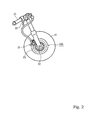
- the vibration is transmitted to a rider via a handlebar 31 and a brake lever 22 (see Fig. 2 and Fig. 11 ).
- a handlebar 31 and a brake lever 22 see Fig. 2 and Fig. 11 .
- the brake disk described in the patent document 1 presents a problem that because the rigidity of the brake disk is high, vibration is easily caused at the time of braking. Summary
- a brake disk includes: a hub; a ring-shaped braking member arranged outside the hub via a gap; and a plurality of coupling members for coupling the hub to the braking member while keeping the gap.
- the hub has a plurality of coupling portions disposed at a plurality of positions in a peripheral direction of an outer edge portion, the plurality of coupling portions being coupled to the braking member by the plurality of coupling members.
- the plurality of coupling portions are coupled to a central portion disposed inside in the radial direction of the coupling portions by arm portions inclined in one peripheral direction with respect to the radial direction.
- the hub and the braking member are coupled to each other while keeping a gap, so that the hub little undergoes the effect of thermal strain caused in the braking member at the time of braking.
- the central portion of the hub and a plurality of coupling portions are coupled to each other by a plurality of arm portions inclined in one rotational direction with respect to the radial direction.
- the plurality of arm portions that keep specified rigidity and which are inclined in the one rotational direction with respect to the radial direction are allowed to be elastically inclined at the time of braking.
- the plurality of arm portions can reduce vibration caused by the braking mechanism or its surroundings.
- a brake disk 100 is provided with a hub 101, a braking member 102, and coupling members 103.
- This brake disk 100 for example, as shown in Fig. 11 , can be applied to a brake disk of a front wheel 11 of a motorcycle 10.
- the brake disk 100 is coaxially fixed to an axle 12 of the wheel 11 and is rotated together with the wheel 11.
- the brake disk 100 is fixed to one side or both sides of the wheel 11, depending on the kind of the vehicle.
- the motorcycle is provided with a brake mechanism 21 such as a caliper operated by a brake lever 22.
- the brake mechanism 21 sandwiches the brake disk 100 by a pair of brake shoes 23 to produce a braking force by a frictional force produced between the brake disk 100 and the brake shoes 23.
- the respective parts to construct the brake disk 100 will be described.
- the hub 101 in this embodiment, is a member fixed to a rotary body (wheel or the like) to be braked and is constructed of a member formed of aluminum in the shape of a circular disk so as to reduce the weight of a brake disk.
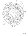
- the hub 101 has a central portion 110, coupling portions 112, and arm portions 113a, 113b.
- the coupling portions 112 are portions coupled to the braking member 102 by coupling members 103 and are disposed at plural positions in a peripheral direction of the outer edge portion of the hub 101.
- the coupling portions 112 are independent from each other at the plural positions (ten positions in this embodiment) in the peripheral direction of the hub 101 and are disposed at equal intervals in the peripheral direction.
- the outer edge portion of the hub 101 is cut out nearly in the shape of a semicircle. This cutout 121 forms a portion of a pin hole.
- the central portion 110 of the hub 101 is formed inside in the radial direction of the coupling portions 112.
- the central portion 110 has a nearly circular opening 114 formed therein, and has fixing portions 111 disposed on the periphery of the opening 114.
- the fixing portions 111 are portions for fixing this brake disk 100 to the other member, and in this embodiment, fix the brake disk 100 to the front wheel 11 of the rotary body to be braked.
- the fixing portions 111 are formed at equal intervals in the peripheral direction and each of the fixing portions 111 has a circular fixing hole formed therein.
- the inside edge portion of the hub 101 is protruded inside to widen the width of the hub 101. With this, when the hub 101 is fixed for use to the rotary body to be braked, the concentration of stress applied to the periphery of the fixing portion 111 is relieved.
- the coupling portions 112 and the central portion 110 described above, as shown in Fig. 1 are coupled to each other by the arm portions 113a, 113b. These arm portions 113a, 113b are inclined in one peripheral direction with respect to a radial direction.
- each of the coupling portions 112 is coupled to the central portion 110 by the plural arm portions 113a, 113b.
- the arm portions 113a, 113b are arranged respectively on both side in the peripheral direction of the coupling portion 112 so as to sandwich the coupling member 103.
- the arm portions 113a, 113b are arranged at equal intervals in the peripheral direction.
- the center C0 of the hub 101 is specified, for example, by the center of a circle C1 passing the centers of the fixing holes formed in the respective fixing portions 111.
- the longitudinal direction E1 (E2) of the arm portion 113a (113b) for example, by the direction of a straight line that passes: a central position C2 (C4) of the width in the peripheral direction of the arm portion 113a (113b) inside in the radial direction of the arm portion 113a (113b); and a central position C3 (C5) of the width in the peripheral direction of the arm portion 113a (113b) outside in the radial direction of the arm_portion 113a (113b).
- the above-mentioned fixing portions 111 are formed between the arm portions 113a, 113b disposed adjacently to each other in tandem in the peripheral direction, of the arm portions 113a, 113b extending from different coupling portions 112 disposed adjacently to each other in tandem in the peripheral direction.
- the fixing portions 111 are formed at five positions selected at equal intervals in the peripheral direction, of the positions in which the arm portions 113a, 113b extending from the different coupling portions 112 combine with each other.
- the braking member 102 is a ring-shaped member and is disposed outside the hub 101 via a gap S.
- the braking member 102 as shown in Fig. 2 , is a member having the brake shoes 23 pressed thereon and is constructed of a ring-shaped flat plate.
- the braking member 102 is a member that has the brake shoes 23 pressed thereon and which easily produces heat by load and friction. For this reason, it is recommended to construct the braking member 102 of a plate made of metal having specified rigidity and wear resistance, for example, iron.
- the braking member 102 has plural holes formed therein, which hence can prevent rain water from entering between the brake shoes 23 and the braking member 102 and can exert a sufficient braking force.
- the braking member 102 has coupling portions 201 coupled to the hub 101 by the coupling members 103 at positions corresponding to the coupling portions 112 disposed in the outer edge of the hub 101.
- the inside edge portion of the braking member 102 is protruded inside.
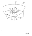
- Each of the coupling portions 201 as shown in Fig. 3 , has its inside edge portion cut out nearly in the shape of a semicircle. This cutout 202 and the cutout 121 formed in the coupling portion 112 on the hub 101 side form the circular pin hole in combination.
- the coupling members 103 couple the hub 101 to the braking member 102 while keeping the gap S between the hub 101 and the braking member 102.
- the coupling member 103 as shown in Fig. 4 , is constructed of a caulking pin 301, a spring washer 302, and a coned disk spring 303.
- the caulking pin 301 has a head portion 312 extending outward in the radial direction on one end of a hollow shaft portion 311.
- the caulking pin 301 as shown in Fig. 4 , is passed through the pin hole formed by the cutouts 121, 202 formed by the coupling portions 112, 201.
- the other end 313 of the caulking pin 301 passed through the pin hole has the coned disk spring 303 and the spring washer 302 passes thereon in this order. Then, as shown in Fig. 5 , the other end 313 of the caulking pin 301 is pressed and expanded outward, whereby the spring washer 302 is fixed in a state where the coned disk spring 303 is pressed onto the side surfaces of the hub 101 and the braking member 102.
- This brake disk 100 for example, as shown in Fig. 1 , the arm portions 113a, 113b of the hub 101 are inclined in one peripheral direction with respect to the radial direction.
- this brake disk 100 is fixed to the wheel 11, it is recommended to fix the brake disk 100 to the wheel 11 in such a way that, on the assumption that a rotational direction in which the wheel 11 is rotated when the vehicle travels forward is t, inside portions in the radial direction of the arm portions 113a, 113b of the hub 101 are positioned forward in the rotational direction t of outside portions in the radial direction.
- Fig. 6 schematically shows the structure of the brake disk 100.
- the hub 101 and the braking member 102 are coupled to each other while keeping the gap S (see Fig. 3 ), so that the hub 101 less undergoes the effect of thermal strain produced in the braking member 102 at the time of braking.
- the central portion 110 of the hub 101 and the coupling portions 112 are coupled to each other by the plural arm portions 113a, 113b inclined in the one rotational direction with respect to the radial direction.
- the arm portions 113a, 113b that ensure specified rigidity and which are inclined in the one rotational direction with respect to the radial direction are allowed to be elastically inclined at the time of braking, which hence can reduce vibration caused by a braking mechanism or its surroundings.
- this brake disk 100 has the coupling members 103 for coupling the hub 101 to the braking member 102 while keeping the gap S between the hub 101 and the braking member 102 (see Fig. 3 ). Since the gap S is interposed between the hub 101 and the braking member 102, the hub 101 less undergoes the effect of heat produced in the braking member 102 at the time of braking. In other words, the frictional heat produced at the time of braking is not transmitted directly to the hub 101 from the braking member 102 and hence does not make as large an effect as greatly deforms the hub 101 by thermal expansion.
- the braking member 102 is expanded by the frictional heat produced at the time of braking, but the gap S is kept between the hub 101 and the braking member 102. For this reason, when the braking member 102 is thermally expanded, the braking member 102 can have its diameter expanded without being constrained by the hub 101 arranged inside. Even when the braking member 102 has its diameter expanded, the braking member 102 does not have an effect on the hub 101 arranged inside the braking member 102 via the gap S.
- the coupling portions 112 coupled to the braking member 102 by the coupling members 103 are disposed at the plural positions in the peripheral direction,.
- the coupling portions 112 and the central portion of the hub 101 are coupled to each other by the plural arm portions 113a, 113b, and the plural arm portions 113a, 113b are inclined in the one peripheral direction with respect to the radial direction.
- the central portion of the hub 101 fixed to the wheel 11 has a force applied thereto in the rotational direction t by the inertia force of the vehicle.
- the coupling portions 112 of the hub 101 fixed to the braking member 102 have a force applied thereto in a direction opposite to the rotational direction t by a braking force. For this reason, as shown in Fig. 6 , the coupling portions 112 have a force P0 applied thereto in a tangential direction.
- the coupling portions 112 are coupled to the central portion 110 of the hub 101 by the plural arm portions 113a, 113b, and the plural arm portions 113a, 113b are inclined in the one peripheral direction with respect to the radial direction.
- each of the coupling portions 112 of the hub 101 has a force P0 applied thereto in the tangential direction via the coupling member 103.
- forces P0a, P0b are applied in the tangential direction to the end portions outside in the radial direction of the arm portions 113a, 113b.
- the forces P0a, P0b applied in the tangential direction to the end portions outside in the radial direction of the arm portions 113a, 113b can be divided into forces: P1a, P1b applied in the longitudinal direction of the arm portions 113a, 113b for coupling the coupling portions 112 to the central portion 110; and P2a, P2b applied in a direction orthogonal to the longitudinal direction.
- the forces P1a, P1b are applied to the arm portions 113a, 113b so as to pull the arm portions 113a, 113b, whereas the forces P2a, P2b are applied to the arm portions 113a, 113b so as to bend the arm portions 113a, 113b. That is, in this brake disk 100, the arm portions 113a, 113b have the pulling forces P1a, P1b and the bending forces P2a, P2b applied thereto at the time of braking.
- the thermal expansion developed in the braking member 102 at the time of braking has little effect on the hub 101, and the plural arm portions 113a, 113b of the hub 101 has the pulling forces P1a, P1b and the bending force P2a, P2b applied thereto.
- the plural arm portions 113a, 113b are inclined in the one peripheral direction with respect to the radial direction, so that at the time of braking, the arm portions 113a, 113b of the hub 101 are elastically deformed in such a way that the outside portion in the radial direction, which has the coupling portions 112 disposed therein, is inclined rearward in the rotational direction t.
- a portion of the force applied to the brake disk 100 at the time of braking can be absorbed by the elastic deformation of the hub 101. For this reason, vibration caused in the braking mechanism and its surroundings at the time of braking can be prevented.
- the plural arm portions 113a, 113b are inclined in the one peripheral direction with respect to the radial direction. For this reason, the arm portions 113a, 113b are longer than the distance in the radial direction between the central portion 110 of the hub 101 and the coupling portion 112. Thus, when the arm portions 113a, 113b are elastically deformed as described above, the arm portions 113a, 113b can be easily bent.
- the braking member 102 can be inclined in the normal direction.
- the gap S is kept between the hub 101 and the braking member 102, and hence even if the braking member 102 is inclined in the normal direction, the effect that the braking member 102 produces on the hub 101 is little.
- the coupling portions 112 are independent of each other at plural positions in the peripheral direction of the hub 101. That is, the respective coupling portions 112 are coupled to the central portion 110 of the hub 101 by the different arm portions 113a, 113b. For this reason, the forces applied to the coupling portions 112 are applied respectively to the arm portions 113a, 113b extending to the coupling portion 112, which can elastically deform the hub 101 suitably. With this, vibration caused by the braking mechanism or its surroundings at the time of braking can be further reduced.
- the respective coupling portions 112 are coupled to the central portion 110 by the plural arm portions 113a, 113b.
- the arm portions 113a, 113b are arranged on both sides in the peripheral direction of the coupling portion 112 across the coupling member 103, respectively.
- the forces applied to the coupling portions 112 can be suitably distributed. With this, vibration caused by the braking mechanism or its surroundings at the time of braking can be further reduced. Further, in this embodiment, as shown in Fig.
- each coupling portion 112 is coupled to the central portion 110 by the plural arm portions 113a, 113b.
- Each of the arm portions 113a, 113b is formed in a shape to allow the arm portions 113a, 113b to be elastically deformed so as to be inclined in the peripheral direction as described above. With this, the forces applied to the coupling portions 112 of the hub 101 via the coupling members 103 from the braking member 102 at the time of braking can be reduced by the elastic deformation of the arm portions 113a, 113b. Further, the deformation and impression of the cutouts 121 of the coupling portions 112 can be made smaller.
- the fixing portions 111 for fixing the brake disk 100 to the other member (wheel 11) are disposed in the central portion 110 of the hub 101.
- each of the fixing portions 111 is interposed between the arm portions 113a, 113b disposed adjacently to each other in tandem in the peripheral direction, of the arm portions 113a, 113b extending from the different coupling portions 112 disposed adjacently to each other in tandem in the peripheral direction.
- the forces applied to the fixing portions 111 can be distributed to the different coupling portions 112 disposed adjacently to each other in tandem in the peripheral direction.
- the pulling forces and the bending forces applied to the arm portions 113a, 113b can be made more uniform.
- vibration caused by the braking mechanism or its surroundings at the time of braking can be further reduced.
- the coupling portions 112 and the arm portions 113a, 113b are disposed at equal intervals in the peripheral direction, so that the pulling forces and the bending forces applied to the respective arm portions 113a, 113b can be made more uniform.
- the number of the arm portions 113a, 113b is increased and the arm portions 113a, 113b are arranged at equal intervals in the peripheral direction of the hub 101. With this, vibration caused by the braking mechanism or its surroundings at the time of braking can be further reduced.
- the brake disk 100 according to the one embodiment of the present invention has been described, but the brake disk according to the present invention is not limited to the above-mentioned embodiment.
- the other embodiments of the brake disk according to the present invention will be described.
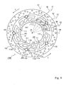
- a brake disk 100A as shown in Fig. 9 , includes the hub 101; the ring-shaped braking member 102 arranged outside the hub 101 via the gap S; and the coupling members 103 for coupling the hub 101 to the braking member 102 while keeping the gap S.
- the coupling portions 112 coupled to the braking member 102 by the coupling members 103 are disposed at plural positions in the peripheral direction on the outer edge portion of the hub 101.
- the central portion 110 of the hub 101 is coupled to the coupling portions 112 by plural arm portions 113a, 113b, 113c, and 113d, and the plural arm portions 113a, 113b, 113c, and 113d are inclined in one peripheral direction with respect to the radial direction.
- the hub 101 and the braking member 102 have the coupling portions 112, 201 disposed therein respectively at five positions arranged at equal intervals in the peripheral direction.
- plural arm portions 113a, 113b, 113c, and 113d extend from the coupling portions 112.
- the arm portions 113a, 113b, 113c, and 113d extend from both sides in the peripheral direction of the coupling portions 112, respectively. That is, the arm portions 113a, 113b are disposed forward in the rotational direction t of the coupling portions 112, respectively, and the arm portions 113c, 113d are disposed rearward in the rotational direction t of the coupling portion 112, respectively.
- the directions E1 to E4 in which the arm portions 113a, 113b, 113c, and 113d extend are inclined in one peripheral direction with respect to the radial directions D1 to D4, respectively.
- the hub 101 and the braking member 102 are coupled to each other while keeping the gap S, so that the hub 101 less undergoes the effect of thermal strain produced in the braking member 102 at the time of braking.
- the central portion 110 of the hub 101 and the coupling portion 112 are coupled to each other by the plural arm portions 113a, 113b, 113c, and 113d inclined in the one rotational direction with respect to the radial direction. For this reason, vibration caused by the braking member 102 or its surroundings at the time of braking can be reduced.
- the number of the arm portions 113a, 113b, 113c, and 113d extending from the respective coupling portions 112 is large, so that the forces applied to the respective arm portions 113a, 113b, 113c, and 113d by the coupling portions 112 at the time of braking can be distributed by that much.
- the central portion 110 of the hub 101 has fixing portions 111 interposed between the arm portions 113a, 113d disposed adjacently to each other in tandem in the peripheral direction, of the arm portions extending from the different coupling portions 112 disposed adjacently to each other in tandem in the peripheral direction, the fixing portions 111 fixing the brake disk to the other member.
- the force applied to the fixing portion 111 can be distributed to the different coupling portions 112 disposed adjacently to each other in tandem in the peripheral direction.
- the number of the coupling portions 112 and the number of the arm portions 113a, 113b, 113c, and 113d may be changed.
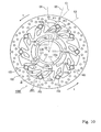
- a brake disk 100B includes the hub 101, the ring-shaped braking member 102 arranged outside the hub 101 via the gap S, and the coupling members 103 for coupling the hub 101 to the braking member 102 while keeping the gap S.
- the coupling portions 112 coupled to the braking member 102 by the coupling portions 103 are disposed at plural positions in the peripheral direction on the outer edge portion of the hub 101.
- the central portion 110 of the hub 101 and the coupling portions 112 are coupled to each other by plural arm portions 113a, 113b, and the plural arm portions 113a, 113b are inclined in one peripheral direction with respect to the radial direction.
- the directions E1, E2 in which the respective arm portions 113a, 113b extend, as shown in Fig. 10 , are inclined in the one peripheral direction with respect to the radial directions D1, D2.
- the arm portions 113a, 113b extend from both sides in the peripheral direction of the coupling portions 112, respectively. That is, the arm portions 113a are disposed forward in the rotational direction t of the coupling portions 112, respectively, whereas the arm portions 113b are disposed rearward in the rotational direction t of the coupling portions 112, respectively.
- the central portion 110 of the hub 101 has an inside ring-shaped portion 110a and an outside ring-shaped portion 110b, and the inside ring-shaped portion 110a and the outside ring-shaped portion 110b are coupled to each other by bridge portions 110c extending in the radial direction.
- Plural arm portions 113a, 113b for coupling the central portion 110 of the hub 101 to the coupling portions 112 are coupled to the outside ring-shaped portion 110b of the central portion 110.
- the fixing portions 111 for fixing the brake disk 100 to the other member (wheel 11) are disposed in the central portion 110 of the hub 101.
- the bridge portions 110c for coupling the inside ring-shaped portion 110a to the outside ring-shaped portion 110b are interposed between the arm portions 113a, 113b extending from the different coupling portions 112 disposed adjacently to each other in tandem in the peripheral direction.
- the fixing portions 111 are disposed in the portions in which the bridge portions 110c cross the inside ring-shaped portion 110a.
- the central portion 110 of the hub 101 has the fixing portions 111 interposed between the arm portions 113a, 113b disposed adjacently to each other in tandem in the peripheral direction, of the arm portions extending from the different coupling portions 112 disposed adjacently to each other in tandem in the peripheral direction, the fixing portions 111 fixing the brake disk 100 to the other member.
- the force applied to the fixing portions 111 can be distributed to the different coupling portions 112 disposed adjacently to each other in tandem in the peripheral direction.
- the pulling force and the bending force applied to each of the arm portions 113a, 113b can be made more uniform, and hence vibration caused by the braking mechanism or its surroundings can be further reduced.
- the fixing portions 111 are disposed at positions in which the bridge portions 110c cross the inside ring-shaped portion 110a, and the portions around the fixing portions 111 are wide in the width of the hub 101. For this reason, stress concentration can be relieved around the fixing portions 111.
- the central portion 110 of the hub 101 has the inside ring-shape portion 110a and the outside ring-shape portion 110b, and the inside ring-shape portion 110a and the outside ring-shape portion 110b are coupled to each other by the bridge portions 110c extending in the radial direction.
- the fixing portions 111 for fixing the brake disk to the other member can be disposed further inside while reducing the weight of the hub 101.
- the brake disk 100 is fixed to the motorcycle 10.
- the brake disk according to the present invention can be applied not only to the motorcycle but also to the other vehicles.
- the brake disk according to the present invention can be applied to a so-called straddle-type vehicle (such as snowmobile, four-wheeled buggy (ATV: All Terrain Vehicle)) in addition to the motorcycle.
- the motorcycle means a motorcycle and includes a motorized bicycle (motorbike) and a scooter, and specifically means a vehicle capable of turning with a vehicle body inclined.
- motorized bicycle motorbike
- scooter specifically means a vehicle capable of turning with a vehicle body inclined.
- the vehicle is included in the "motorcycle”.
Landscapes
- Engineering & Computer Science (AREA)
- General Engineering & Computer Science (AREA)
- Mechanical Engineering (AREA)
- Braking Arrangements (AREA)
Applications Claiming Priority (1)
| Application Number | Priority Date | Filing Date | Title |
|---|---|---|---|
| JP2008062106A JP2009216205A (ja) | 2008-03-12 | 2008-03-12 | ブレーキディスクおよび車両 |
Publications (3)
| Publication Number | Publication Date |
|---|---|
| EP2101076A2 true EP2101076A2 (de) | 2009-09-16 |
| EP2101076A3 EP2101076A3 (de) | 2010-03-10 |
| EP2101076B1 EP2101076B1 (de) | 2011-08-03 |
Family
ID=40793104
Family Applications (1)
| Application Number | Title | Priority Date | Filing Date |
|---|---|---|---|
| EP09250592A Not-in-force EP2101076B1 (de) | 2008-03-12 | 2009-03-02 | Bremsscheibe und Fahrzeug |
Country Status (4)
| Country | Link |
|---|---|
| EP (1) | EP2101076B1 (de) |
| JP (1) | JP2009216205A (de) |
| AT (1) | ATE519040T1 (de) |
| ES (1) | ES2370693T3 (de) |
Cited By (2)
| Publication number | Priority date | Publication date | Assignee | Title |
|---|---|---|---|---|
| EP2759507A1 (de) * | 2013-01-24 | 2014-07-30 | Kone Corporation | Aufzugsantrieb |
| CN113614404A (zh) * | 2019-03-22 | 2021-11-05 | 新时代技研株式会社 | 旋转传递盘 |
Families Citing this family (1)
| Publication number | Priority date | Publication date | Assignee | Title |
|---|---|---|---|---|
| JP5783856B2 (ja) * | 2011-09-06 | 2015-09-24 | 株式会社ユタカ技研 | フローティング型ブレーキディスク |
Family Cites Families (4)
| Publication number | Priority date | Publication date | Assignee | Title |
|---|---|---|---|---|
| DE1530246A1 (de) * | 1965-01-15 | 1969-10-23 | Knorr Bremse Gmbh | Bremsscheibe fuer Schienenfahrzeugraeder |
| US7374025B2 (en) * | 2003-10-23 | 2008-05-20 | Yamaha Hatsudoki Kabushiki Kaisha | Brake Disc |
| DE102004002710A1 (de) * | 2004-01-19 | 2005-08-04 | Gustav Magenwirth Gmbh & Co. Kg | Bremsscheibe |
| JP4481074B2 (ja) * | 2004-04-28 | 2010-06-16 | 株式会社ユタカ技研 | フローティング型ブレーキディスク |
-
2008
- 2008-03-12 JP JP2008062106A patent/JP2009216205A/ja not_active Withdrawn
-
2009
- 2009-03-02 EP EP09250592A patent/EP2101076B1/de not_active Not-in-force
- 2009-03-02 AT AT09250592T patent/ATE519040T1/de not_active IP Right Cessation
- 2009-03-02 ES ES09250592T patent/ES2370693T3/es active Active
Non-Patent Citations (1)
| Title |
|---|
| None |
Cited By (3)
| Publication number | Priority date | Publication date | Assignee | Title |
|---|---|---|---|---|
| EP2759507A1 (de) * | 2013-01-24 | 2014-07-30 | Kone Corporation | Aufzugsantrieb |
| CN113614404A (zh) * | 2019-03-22 | 2021-11-05 | 新时代技研株式会社 | 旋转传递盘 |
| CN113614404B (zh) * | 2019-03-22 | 2024-03-15 | 新时代技研株式会社 | 旋转传递盘 |
Also Published As
| Publication number | Publication date |
|---|---|
| EP2101076B1 (de) | 2011-08-03 |
| EP2101076A3 (de) | 2010-03-10 |
| JP2009216205A (ja) | 2009-09-24 |
| ES2370693T3 (es) | 2011-12-21 |
| ATE519040T1 (de) | 2011-08-15 |
Similar Documents
| Publication | Publication Date | Title |
|---|---|---|
| US8522931B2 (en) | Disk brake rotor | |
| JP5393969B2 (ja) | ディスクブレーキキャリパ | |
| TWI500862B (zh) | 自行車盤式制動器轉子 | |
| US8474580B2 (en) | Floating brake disc | |
| US11274717B2 (en) | Brake rotor assembly | |
| JP3545373B2 (ja) | 自転車用ハブアッセンブリ | |
| US7575107B2 (en) | Brake disc | |
| TWI663343B (zh) | 熱消散剎車轉子 | |
| JP7129171B2 (ja) | 自転車用のブレーキディスク | |
| CN104747625A (zh) | 自行车制动衬块 | |
| US20100052411A1 (en) | Bicycle wheel assembly having dissimilar lateral spoke lacings | |
| US20210277969A1 (en) | Disc brake caliper body | |
| EP2101076B1 (de) | Bremsscheibe und Fahrzeug | |
| CN107575511B (zh) | 用于自行车的制动盘 | |
| US7926625B2 (en) | Disk braking device and motorcycle provided with the disk braking device | |
| US8813921B2 (en) | Bicycle disc brake rotor | |
| JP4845042B2 (ja) | ドラムブレーキ並びにブレーキライニング、及び鞍乗型車両 | |
| JP2009250330A (ja) | ブレーキディスク | |
| EP3521651B1 (de) | Bremsscheibenanordnung | |
| JP7478125B2 (ja) | フローティング型ブレーキディスク並びに鞍乗り型車両用の車輪 | |
| TW202417306A (zh) | 用於人力車輛之碟式煞車轉子 | |
| CN116097017A (zh) | 卡钳本体及具有该本体的制动器卡钳 | |
| JPH09250577A (ja) | デイスクブレーキ装置 | |
| TW202611414A (zh) | 用於人力驅動車之碟剎碟盤 | |
| JP2016017628A (ja) | ドラムブレーキの支持構造 |
Legal Events
| Date | Code | Title | Description |
|---|---|---|---|
| PUAI | Public reference made under article 153(3) epc to a published international application that has entered the european phase |
Free format text: ORIGINAL CODE: 0009012 |
|
| AK | Designated contracting states |
Kind code of ref document: A2 Designated state(s): AT BE BG CH CY CZ DE DK EE ES FI FR GB GR HR HU IE IS IT LI LT LU LV MC MK MT NL NO PL PT RO SE SI SK TR |
|
| AX | Request for extension of the european patent |
Extension state: AL BA RS |
|
| PUAL | Search report despatched |
Free format text: ORIGINAL CODE: 0009013 |
|
| AK | Designated contracting states |
Kind code of ref document: A3 Designated state(s): AT BE BG CH CY CZ DE DK EE ES FI FR GB GR HR HU IE IS IT LI LT LU LV MC MK MT NL NO PL PT RO SE SI SK TR |
|
| AX | Request for extension of the european patent |
Extension state: AL BA RS |
|
| RIC1 | Information provided on ipc code assigned before grant |
Ipc: F16D 65/00 20060101ALI20100129BHEP Ipc: F16D 65/12 20060101AFI20090702BHEP |
|
| 17P | Request for examination filed |
Effective date: 20100906 |
|
| AKX | Designation fees paid |
Designated state(s): AT BE BG CH CY CZ DE DK EE ES FI FR GB GR HR HU IE IS IT LI LT LU LV MC MK MT NL NO PL PT RO SE SI SK TR |
|
| GRAP | Despatch of communication of intention to grant a patent |
Free format text: ORIGINAL CODE: EPIDOSNIGR1 |
|
| GRAS | Grant fee paid |
Free format text: ORIGINAL CODE: EPIDOSNIGR3 |
|
| GRAA | (expected) grant |
Free format text: ORIGINAL CODE: 0009210 |
|
| AK | Designated contracting states |
Kind code of ref document: B1 Designated state(s): AT BE BG CH CY CZ DE DK EE ES FI FR GB GR HR HU IE IS IT LI LT LU LV MC MK MT NL NO PL PT RO SE SI SK TR |
|
| REG | Reference to a national code |
Ref country code: GB Ref legal event code: FG4D |
|
| REG | Reference to a national code |
Ref country code: CH Ref legal event code: EP |
|
| REG | Reference to a national code |
Ref country code: IE Ref legal event code: FG4D |
|
| REG | Reference to a national code |
Ref country code: DE Ref legal event code: R096 Ref document number: 602009001980 Country of ref document: DE Effective date: 20111013 |
|
| REG | Reference to a national code |
Ref country code: NL Ref legal event code: VDEP Effective date: 20110803 |
|
| REG | Reference to a national code |
Ref country code: ES Ref legal event code: FG2A Ref document number: 2370693 Country of ref document: ES Kind code of ref document: T3 Effective date: 20111221 |
|
| LTIE | Lt: invalidation of european patent or patent extension |
Effective date: 20110803 |
|
| PG25 | Lapsed in a contracting state [announced via postgrant information from national office to epo] |
Ref country code: PT Free format text: LAPSE BECAUSE OF FAILURE TO SUBMIT A TRANSLATION OF THE DESCRIPTION OR TO PAY THE FEE WITHIN THE PRESCRIBED TIME-LIMIT Effective date: 20111205 Ref country code: LT Free format text: LAPSE BECAUSE OF FAILURE TO SUBMIT A TRANSLATION OF THE DESCRIPTION OR TO PAY THE FEE WITHIN THE PRESCRIBED TIME-LIMIT Effective date: 20110803 Ref country code: FI Free format text: LAPSE BECAUSE OF FAILURE TO SUBMIT A TRANSLATION OF THE DESCRIPTION OR TO PAY THE FEE WITHIN THE PRESCRIBED TIME-LIMIT Effective date: 20110803 Ref country code: HR Free format text: LAPSE BECAUSE OF FAILURE TO SUBMIT A TRANSLATION OF THE DESCRIPTION OR TO PAY THE FEE WITHIN THE PRESCRIBED TIME-LIMIT Effective date: 20110803 Ref country code: NL Free format text: LAPSE BECAUSE OF FAILURE TO SUBMIT A TRANSLATION OF THE DESCRIPTION OR TO PAY THE FEE WITHIN THE PRESCRIBED TIME-LIMIT Effective date: 20110803 Ref country code: SE Free format text: LAPSE BECAUSE OF FAILURE TO SUBMIT A TRANSLATION OF THE DESCRIPTION OR TO PAY THE FEE WITHIN THE PRESCRIBED TIME-LIMIT Effective date: 20110803 Ref country code: NO Free format text: LAPSE BECAUSE OF FAILURE TO SUBMIT A TRANSLATION OF THE DESCRIPTION OR TO PAY THE FEE WITHIN THE PRESCRIBED TIME-LIMIT Effective date: 20111103 Ref country code: IS Free format text: LAPSE BECAUSE OF FAILURE TO SUBMIT A TRANSLATION OF THE DESCRIPTION OR TO PAY THE FEE WITHIN THE PRESCRIBED TIME-LIMIT Effective date: 20111203 |
|
| REG | Reference to a national code |
Ref country code: AT Ref legal event code: MK05 Ref document number: 519040 Country of ref document: AT Kind code of ref document: T Effective date: 20110803 |
|
| PG25 | Lapsed in a contracting state [announced via postgrant information from national office to epo] |
Ref country code: SI Free format text: LAPSE BECAUSE OF FAILURE TO SUBMIT A TRANSLATION OF THE DESCRIPTION OR TO PAY THE FEE WITHIN THE PRESCRIBED TIME-LIMIT Effective date: 20110803 Ref country code: AT Free format text: LAPSE BECAUSE OF FAILURE TO SUBMIT A TRANSLATION OF THE DESCRIPTION OR TO PAY THE FEE WITHIN THE PRESCRIBED TIME-LIMIT Effective date: 20110803 Ref country code: PL Free format text: LAPSE BECAUSE OF FAILURE TO SUBMIT A TRANSLATION OF THE DESCRIPTION OR TO PAY THE FEE WITHIN THE PRESCRIBED TIME-LIMIT Effective date: 20110803 Ref country code: CY Free format text: LAPSE BECAUSE OF FAILURE TO SUBMIT A TRANSLATION OF THE DESCRIPTION OR TO PAY THE FEE WITHIN THE PRESCRIBED TIME-LIMIT Effective date: 20110803 Ref country code: LV Free format text: LAPSE BECAUSE OF FAILURE TO SUBMIT A TRANSLATION OF THE DESCRIPTION OR TO PAY THE FEE WITHIN THE PRESCRIBED TIME-LIMIT Effective date: 20110803 Ref country code: GR Free format text: LAPSE BECAUSE OF FAILURE TO SUBMIT A TRANSLATION OF THE DESCRIPTION OR TO PAY THE FEE WITHIN THE PRESCRIBED TIME-LIMIT Effective date: 20111104 |
|
| PG25 | Lapsed in a contracting state [announced via postgrant information from national office to epo] |
Ref country code: BE Free format text: LAPSE BECAUSE OF FAILURE TO SUBMIT A TRANSLATION OF THE DESCRIPTION OR TO PAY THE FEE WITHIN THE PRESCRIBED TIME-LIMIT Effective date: 20110803 |
|
| PG25 | Lapsed in a contracting state [announced via postgrant information from national office to epo] |
Ref country code: SK Free format text: LAPSE BECAUSE OF FAILURE TO SUBMIT A TRANSLATION OF THE DESCRIPTION OR TO PAY THE FEE WITHIN THE PRESCRIBED TIME-LIMIT Effective date: 20110803 Ref country code: CZ Free format text: LAPSE BECAUSE OF FAILURE TO SUBMIT A TRANSLATION OF THE DESCRIPTION OR TO PAY THE FEE WITHIN THE PRESCRIBED TIME-LIMIT Effective date: 20110803 |
|
| PG25 | Lapsed in a contracting state [announced via postgrant information from national office to epo] |
Ref country code: RO Free format text: LAPSE BECAUSE OF FAILURE TO SUBMIT A TRANSLATION OF THE DESCRIPTION OR TO PAY THE FEE WITHIN THE PRESCRIBED TIME-LIMIT Effective date: 20110803 Ref country code: EE Free format text: LAPSE BECAUSE OF FAILURE TO SUBMIT A TRANSLATION OF THE DESCRIPTION OR TO PAY THE FEE WITHIN THE PRESCRIBED TIME-LIMIT Effective date: 20110803 |
|
| PLBE | No opposition filed within time limit |
Free format text: ORIGINAL CODE: 0009261 |
|
| STAA | Information on the status of an ep patent application or granted ep patent |
Free format text: STATUS: NO OPPOSITION FILED WITHIN TIME LIMIT |
|
| PG25 | Lapsed in a contracting state [announced via postgrant information from national office to epo] |
Ref country code: DK Free format text: LAPSE BECAUSE OF FAILURE TO SUBMIT A TRANSLATION OF THE DESCRIPTION OR TO PAY THE FEE WITHIN THE PRESCRIBED TIME-LIMIT Effective date: 20110803 |
|
| 26N | No opposition filed |
Effective date: 20120504 |
|
| REG | Reference to a national code |
Ref country code: DE Ref legal event code: R097 Ref document number: 602009001980 Country of ref document: DE Effective date: 20120504 |
|
| PG25 | Lapsed in a contracting state [announced via postgrant information from national office to epo] |
Ref country code: MC Free format text: LAPSE BECAUSE OF NON-PAYMENT OF DUE FEES Effective date: 20120331 |
|
| REG | Reference to a national code |
Ref country code: IE Ref legal event code: MM4A |
|
| PG25 | Lapsed in a contracting state [announced via postgrant information from national office to epo] |
Ref country code: IE Free format text: LAPSE BECAUSE OF NON-PAYMENT OF DUE FEES Effective date: 20120302 |
|
| PG25 | Lapsed in a contracting state [announced via postgrant information from national office to epo] |
Ref country code: MK Free format text: LAPSE BECAUSE OF FAILURE TO SUBMIT A TRANSLATION OF THE DESCRIPTION OR TO PAY THE FEE WITHIN THE PRESCRIBED TIME-LIMIT Effective date: 20110803 |
|
| PG25 | Lapsed in a contracting state [announced via postgrant information from national office to epo] |
Ref country code: BG Free format text: LAPSE BECAUSE OF FAILURE TO SUBMIT A TRANSLATION OF THE DESCRIPTION OR TO PAY THE FEE WITHIN THE PRESCRIBED TIME-LIMIT Effective date: 20111103 |
|
| PG25 | Lapsed in a contracting state [announced via postgrant information from national office to epo] |
Ref country code: MT Free format text: LAPSE BECAUSE OF FAILURE TO SUBMIT A TRANSLATION OF THE DESCRIPTION OR TO PAY THE FEE WITHIN THE PRESCRIBED TIME-LIMIT Effective date: 20110803 |
|
| REG | Reference to a national code |
Ref country code: CH Ref legal event code: PL |
|
| PG25 | Lapsed in a contracting state [announced via postgrant information from national office to epo] |
Ref country code: CH Free format text: LAPSE BECAUSE OF NON-PAYMENT OF DUE FEES Effective date: 20130331 Ref country code: LI Free format text: LAPSE BECAUSE OF NON-PAYMENT OF DUE FEES Effective date: 20130331 |
|
| PG25 | Lapsed in a contracting state [announced via postgrant information from national office to epo] |
Ref country code: TR Free format text: LAPSE BECAUSE OF FAILURE TO SUBMIT A TRANSLATION OF THE DESCRIPTION OR TO PAY THE FEE WITHIN THE PRESCRIBED TIME-LIMIT Effective date: 20110803 |
|
| PG25 | Lapsed in a contracting state [announced via postgrant information from national office to epo] |
Ref country code: LU Free format text: LAPSE BECAUSE OF NON-PAYMENT OF DUE FEES Effective date: 20120302 |
|
| PG25 | Lapsed in a contracting state [announced via postgrant information from national office to epo] |
Ref country code: HU Free format text: LAPSE BECAUSE OF FAILURE TO SUBMIT A TRANSLATION OF THE DESCRIPTION OR TO PAY THE FEE WITHIN THE PRESCRIBED TIME-LIMIT Effective date: 20090302 |
|
| REG | Reference to a national code |
Ref country code: FR Ref legal event code: PLFP Year of fee payment: 8 |
|
| REG | Reference to a national code |
Ref country code: FR Ref legal event code: PLFP Year of fee payment: 9 |
|
| REG | Reference to a national code |
Ref country code: FR Ref legal event code: PLFP Year of fee payment: 10 |
|
| PGFP | Annual fee paid to national office [announced via postgrant information from national office to epo] |
Ref country code: DE Payment date: 20200320 Year of fee payment: 12 Ref country code: GB Payment date: 20200323 Year of fee payment: 12 |
|
| PGFP | Annual fee paid to national office [announced via postgrant information from national office to epo] |
Ref country code: FR Payment date: 20200319 Year of fee payment: 12 |
|
| PGFP | Annual fee paid to national office [announced via postgrant information from national office to epo] |
Ref country code: ES Payment date: 20200522 Year of fee payment: 12 |
|
| PGFP | Annual fee paid to national office [announced via postgrant information from national office to epo] |
Ref country code: IT Payment date: 20200318 Year of fee payment: 12 |
|
| REG | Reference to a national code |
Ref country code: DE Ref legal event code: R119 Ref document number: 602009001980 Country of ref document: DE |
|
| GBPC | Gb: european patent ceased through non-payment of renewal fee |
Effective date: 20210302 |
|
| PG25 | Lapsed in a contracting state [announced via postgrant information from national office to epo] |
Ref country code: DE Free format text: LAPSE BECAUSE OF NON-PAYMENT OF DUE FEES Effective date: 20211001 Ref country code: FR Free format text: LAPSE BECAUSE OF NON-PAYMENT OF DUE FEES Effective date: 20210331 Ref country code: GB Free format text: LAPSE BECAUSE OF NON-PAYMENT OF DUE FEES Effective date: 20210302 |
|
| PG25 | Lapsed in a contracting state [announced via postgrant information from national office to epo] |
Ref country code: IT Free format text: LAPSE BECAUSE OF NON-PAYMENT OF DUE FEES Effective date: 20210302 |
|
| REG | Reference to a national code |
Ref country code: ES Ref legal event code: FD2A Effective date: 20220517 |
|
| PG25 | Lapsed in a contracting state [announced via postgrant information from national office to epo] |
Ref country code: ES Free format text: LAPSE BECAUSE OF NON-PAYMENT OF DUE FEES Effective date: 20210303 |