EP2101963B1 - Mécanisme vermiculaire - Google Patents
Mécanisme vermiculaire Download PDFInfo
- Publication number
- EP2101963B1 EP2101963B1 EP07818968.5A EP07818968A EP2101963B1 EP 2101963 B1 EP2101963 B1 EP 2101963B1 EP 07818968 A EP07818968 A EP 07818968A EP 2101963 B1 EP2101963 B1 EP 2101963B1
- Authority
- EP
- European Patent Office
- Prior art keywords
- elements
- actuating
- supporting
- actuating unit
- support structure
- Prior art date
- Legal status (The legal status is an assumption and is not a legal conclusion. Google has not performed a legal analysis and makes no representation as to the accuracy of the status listed.)
- Not-in-force
Links
Images


Classifications
-
- B—PERFORMING OPERATIONS; TRANSPORTING
- B25—HAND TOOLS; PORTABLE POWER-DRIVEN TOOLS; MANIPULATORS
- B25J—MANIPULATORS; CHAMBERS PROVIDED WITH MANIPULATION DEVICES
- B25J18/00—Arms
- B25J18/06—Arms flexible
-
- A—HUMAN NECESSITIES
- A61—MEDICAL OR VETERINARY SCIENCE; HYGIENE
- A61B—DIAGNOSIS; SURGERY; IDENTIFICATION
- A61B1/00—Instruments for performing medical examinations of the interior of cavities or tubes of the body by visual or photographical inspection, e.g. endoscopes; Illuminating arrangements therefor
- A61B1/00147—Holding or positioning arrangements
- A61B1/00156—Holding or positioning arrangements using self propulsion
-
- B—PERFORMING OPERATIONS; TRANSPORTING
- B25—HAND TOOLS; PORTABLE POWER-DRIVEN TOOLS; MANIPULATORS
- B25J—MANIPULATORS; CHAMBERS PROVIDED WITH MANIPULATION DEVICES
- B25J19/00—Accessories fitted to manipulators, e.g. for monitoring, for viewing; Safety devices combined with or specially adapted for use in connection with manipulators
- B25J19/0025—Means for supplying energy to the end effector
-
- B—PERFORMING OPERATIONS; TRANSPORTING
- B25—HAND TOOLS; PORTABLE POWER-DRIVEN TOOLS; MANIPULATORS
- B25J—MANIPULATORS; CHAMBERS PROVIDED WITH MANIPULATION DEVICES
- B25J9/00—Program-controlled manipulators
- B25J9/06—Program-controlled manipulators characterised by multi-articulated arms
-
- B—PERFORMING OPERATIONS; TRANSPORTING
- B25—HAND TOOLS; PORTABLE POWER-DRIVEN TOOLS; MANIPULATORS
- B25J—MANIPULATORS; CHAMBERS PROVIDED WITH MANIPULATION DEVICES
- B25J9/00—Program-controlled manipulators
- B25J9/10—Program-controlled manipulators characterised by positioning means for manipulator elements
- B25J9/1075—Program-controlled manipulators characterised by positioning means for manipulator elements with muscles or tendons
-
- B—PERFORMING OPERATIONS; TRANSPORTING
- B25—HAND TOOLS; PORTABLE POWER-DRIVEN TOOLS; MANIPULATORS
- B25J—MANIPULATORS; CHAMBERS PROVIDED WITH MANIPULATION DEVICES
- B25J9/00—Program-controlled manipulators
- B25J9/10—Program-controlled manipulators characterised by positioning means for manipulator elements
- B25J9/14—Program-controlled manipulators characterised by positioning means for manipulator elements fluid
- B25J9/142—Program-controlled manipulators characterised by positioning means for manipulator elements fluid comprising inflatable bodies
-
- Y—GENERAL TAGGING OF NEW TECHNOLOGICAL DEVELOPMENTS; GENERAL TAGGING OF CROSS-SECTIONAL TECHNOLOGIES SPANNING OVER SEVERAL SECTIONS OF THE IPC; TECHNICAL SUBJECTS COVERED BY FORMER USPC CROSS-REFERENCE ART COLLECTIONS [XRACs] AND DIGESTS
- Y10—TECHNICAL SUBJECTS COVERED BY FORMER USPC
- Y10T—TECHNICAL SUBJECTS COVERED BY FORMER US CLASSIFICATION
- Y10T74/00—Machine element or mechanism
- Y10T74/20—Control lever and linkage systems
- Y10T74/20207—Multiple controlling elements for single controlled element
- Y10T74/20305—Robotic arm
-
- Y—GENERAL TAGGING OF NEW TECHNOLOGICAL DEVELOPMENTS; GENERAL TAGGING OF CROSS-SECTIONAL TECHNOLOGIES SPANNING OVER SEVERAL SECTIONS OF THE IPC; TECHNICAL SUBJECTS COVERED BY FORMER USPC CROSS-REFERENCE ART COLLECTIONS [XRACs] AND DIGESTS
- Y10—TECHNICAL SUBJECTS COVERED BY FORMER USPC
- Y10T—TECHNICAL SUBJECTS COVERED BY FORMER US CLASSIFICATION
- Y10T74/00—Machine element or mechanism
- Y10T74/20—Control lever and linkage systems
- Y10T74/20207—Multiple controlling elements for single controlled element
- Y10T74/20305—Robotic arm
- Y10T74/20329—Joint between elements
Definitions
- the invention relates to a worm-shaped mechanism, in particular a worm or snake-like deformable handling mechanism, as well as a modular actuator unit for such a mechanism.
- Worm or snake-like mechanisms are known, for example for endoscopy, which consist of a continuously deformable carrier. On this support are provided at certain intervals vertically spaced discs with attachment points, which are connected to the ends of wire ropes, which are guided along the support. If one or more of these wire ropes tensioned, this leads to a curvature of the mechanism.
- a worm-shaped working mechanism which has a zugelastician restoring device as a central support member on which at right angles disc-shaped support elements are attached at certain intervals.
- three actuators are provided, each consisting of a series of adjacent pockets or cushions.
- the individual pockets or cushions are each between two support elements.
- Each of these actuators can be supplied via a separate access channel, a liquid or gaseous pressure medium, so that the cushions of the actuators occupy different volumes depending on the filling state.
- the pillows press each other apart. If the three actuators applied uniformly with pressure medium, so there is a change in length of the drive mechanism. If, however, the three actuators act differently, the result is a corresponding curvature of the working mechanism.
- the pillows are hereby individually or in groups each equipped with its own supply for the pressure medium.
- a snake-like, flexible gripper arm structure which has three sections, each with a plurality of actuating units.
- This central unit is located outside
- the flexible gripper arm structure and is usually large and heavy. Above all, however, resulting from this design large line lengths, so that it comes as a result of the resulting dead times to poor control or controllability of the mechanism.
- the base of the gripper arm through which all lines are guided, has a large circumference, which grows with the length of the gripper arm and / or the number of segments. As a result, such mechanisms usually become very thick relative to their length, which significantly limits their mobility.
- the JP 05-293787 relates to a worm-shaped mechanism in which the individual cells of the adjusting elements are connected via throttle openings with a pressure line, so that they are constantly supplied with a pressure medium. In order to realize different expansion states of the individual cells, pressure can be released from the cells via valves.
- the US 5,337,732 A shows a worm-shaped mechanism, the individual operating units have balloons with which the operating units can invest in a body cavity on the walls in order then to move caterpillar forward.
- the required change in length ie a contraction and expansion, is realized by a piston-cylinder unit, which causes an extension or a shortening of the distance to the adjacent actuating unit depending on the pressurization.
- actuation units can also be provided which are provided with four bags arranged distributed around the longitudinal axis of the actuation unit, each of which can be pressurized via a first valve and vented via a second valve in order to cause bending of the worm-shaped mechanism.
- the EP 0 017 016 A1 relates to a flexible robot arm having two or more sections, each consisting of a plurality of cushions or elements held in contact with one another via corresponding convex surfaces be that a bending of the spinal column structure is possible.
- piston cylinder arrangements are arranged between flanges of adjacent elements in order to press them apart on the outer side of a bend.
- Each cylinder is supplied with compressed air from a supply line via an inlet / outlet.
- the air present in the cylinders is correspondingly pushed out via the outlet / inlet and the feed line, which now serves as a discharge line.
- the elements can also be divided, and have two opposing flange elements, between which servomotors, which are formed for example as hydraulic or pneumatic bellows, are provided.
- servomotors which are formed for example as hydraulic or pneumatic bellows.
- the pressurization and pressure relief takes place again via corresponding feed or discharge lines. All elements of a section are simultaneously actuated in the same way.
- the DE 44 08 730 A1 describes a controllable instrument channel in which the actuators are embedded in the channel jacket.
- These actuators may be, for example, strips of shape memory or bimetallic strip.
- strain gauges, switches or pressure sensors can also be positioned in or on the channel jacket.
- the US 5,897,488 A relates to an endoscope or catheter having a bending portion with a plurality of links.
- pull wires are provided, which are operated by artificial muscles.
- the EP 0 249 318 A1 describes actuating elements for a robot or manipulator arm, in which rods or rods of spring steel or the like form a laying section.
- the rods or rods are connected at their one ends with adjusting elements, while their other ends are held on a support plate. With the help of the adjusting elements, the rods or rods can be rotated in order to realize a rotation of the support plate relative to the base portion. To get bends of the bending section, the rods can be moved in their longitudinal direction by means of piston-cylinder units that can be operated in both directions.
- the invention has for its object to provide a further worm-shaped mechanism that allows precise control or regulation of its movements, especially in a simplified slim design.
- a worm-shaped mechanism having a support structure extending in the longitudinal direction of the mechanism and having at least two actuating units arranged one after the other in the longitudinal direction of the support structure, each having two support elements and at least one actuating element arranged between the support elements, by which the support elements are relative to each other are movable, provided that the actuators are individually controlled via a central line.
- the actuators are hydraulic or pneumatic, at least working on train actuators, each connected via a valve to the central line, which is a supply line for supplying a hydraulic or pneumatic working fluid to the actuators.
- the central control of the actuators in the actuators to deform the mechanism via a central conduit extending along the worm-shaped mechanism allows for short switching times which are also suitable for individual readjustment of the movements or deformations achieved by the individual actuator units.
- it allows the use of hydraulic or pneumatic actuators, where a working medium is supplied via valves from a central line, which may be formed as a tube or hose, which is under pressure, that the working or pressure medium without substantial dead times on the central Supply line connected valves the individual actuators can be supplied quickly. Since the valves are arranged close to the actuators, extremely short supply paths to the actuators result, whereby the effective switching times can be drastically shortened.
- valves each have a first open position for connecting the one or more actuators to the supply line, a closed position and a second open position for discharging the working medium from the one or more actuators.
- valves for relieving the pneumatic or hydraulic actuators in their second open position the actuators connect to the environment, if a gas or liquid is used as the working medium, without risk to the environment or the working environment in which Mechanism is used, can be drained into the environment.
- the valves in the second open position connect the actuators with a return line of the outlet with an outlet.
- the return line can also be designed as a suction or vacuum line and connected to a corresponding vacuum source to accelerate the pressure reduction in the actuators.
- valves by means of piezo elements in particular by means of a construction of stacked piezo elements are switchable. This makes it possible to achieve fast and reliable switchability of the valves.
- each actuating unit has a driver circuit which is connected to a central control circuit and supplies the switching signals for the valves of the actuating unit in response to control information received from the central control circuit, the driver circuit comprising a control information processing circuit Generates control signals for the valve switching valve switching circuits in response to the received control information.
- each actuating unit has one or more motion sensors whose output signals are detected by the driver circuit.
- the driver circuit If the control information for each actuator is determined centrally, it is expedient for the driver circuit to have a transmission circuit for the transmission of the output signals from the motion sensor (s) to the central control circuit.
- the driver circuit has a regulator circuit to which the control information received from the central control circuit and the Output signals from the one or more motion sensors are supplied as control information and the control signals for the valve switching valve switching circuits in response to the control information supplies.
- motion sensor for kink Longitudinal or rotational movements can expediently be provided one or more strain gauges, which are mounted on the support structure.
- strain gauges which are mounted on the support structure.
- immersion coils between the support elements of the actuation unit in such a way that they detect the relative movement of the support elements.
- an optical position detector with a light source and a position-sensitive photoreceiver which are each arranged on mutually movable elements of the actuator, wherein the position detector provides the relative movement between these elements corresponding output signal.
- actuators pressure cylinder or under pressure contracting pneumatic or hydraulic working elements in particular so-called artificial muscles may be provided. It is also possible to combine the different variable-length actuators depending on the desired movements and the controllability or controllability with each other.
- the actuators deliver a return action when pressure relief. Furthermore, it is expedient in various applications that the actuators are assigned one or more restoring elements.
- each actuating element of an actuating unit is assigned one or more oppositely acting actuating elements, the actuating elements can then take on the role of muscles which, like protagonist and antagonist, work together in order to be able to carry out a defined movement very precisely.
- the one or more actuators are arranged in the actuator unit so that they cause a change in length when activated.
- two, three or more actuators are arranged so that they effect a defined tilting of the two support elements against each other in a defined radial direction with appropriate activation.
- the actuating elements are arranged in an actuating unit such that they cause a rotation of the two support elements about the longitudinal direction of the support structure upon activation.
- a worm-like mechanism in a worm-like mechanism according to the present invention, various actuator units can be combined, each causing only a change in length or bending or tilting or rotation about the axis of the worm-shaped mechanism. But it is also possible to combine the various movements in an operating unit, wherein the central support and / or the storage of the support elements must be designed so that the support elements of the operating unit can follow the desired movements and deformations.
- the support elements are designed as support disks, which have a passage for the central line.
- the passage for the central line need not lie in the region of the central axis of the mechanism, but may also be laterally offset.
- the central line is to be interpreted in each case so that they can easily follow the movements of the individual operating units without disturbing them.
- the support structure has a continuously deformable tubular or tubular support, on which the support element are fixed in defined axial distances.
- the support structure consists of a plurality of similar carrier segments which are connected to one another in a modular manner.
- the modular support segments can also consist of tubular or tubular supports with supporting elements arranged thereon, wherein the tubular or tubular support sections must be equipped at their ends with corresponding coupling members, so that the built-up, finished, worm-like mechanism as a support structure has a continuous, comprises deformable carrier, which is composed of individual sections.
- each of the actuating units has a carrier segment, which comprises a first support plate which is fixedly connected to one end of a longitudinal member, and a second support plate which pivotally and / or rotatably on the other via a hinge connection End of the longitudinal member is held, wherein the first support plate has on its side facing away from the side member fastening means for fixing a second support plate of an adjacent support segment.
- each of the actuating units comprises a support segment which has a support plate which is fixedly connected to one end of a longitudinal member and which carries on its side facing away from the longitudinal member a spherical plain bearing, wherein the longitudinal member at its other Ends a corresponding with the hinge bearing hinge member carries, so that the longitudinal member of an operating unit is pivotally and / or rotatably mounted in the hinge bearing on the support plate of the next operating unit.
- FIG. 1 shows a first embodiment of a worm-shaped mechanism according to the invention with a support structure 10 which is formed as a continuously deformable carrier, as will be explained in more detail below.
- a support structure 10 which is formed as a continuously deformable carrier, as will be explained in more detail below.
- supporting elements 11 are arranged, which may be formed, for example, as plates or discs, but also as star or cross-shaped support struts.
- actuating elements 12 are arranged, which in FIG. 1 are indicated as artificial muscles that shorten when pressurized.
- each two adjacent support members 11 together with the intermediate actuators 12 and the portion of the support structure 10 between the actuators 12 form an actuator unit 14, wherein in the in FIG. 1 illustrated embodiment of the Invention, the support members 11 each belong to two adjacent actuator units 14.
- FIG. 12 shows another deformable worm-shaped mechanism according to the present invention in which the support structure 20 is spinal-like and has support segments 21, each having a side rail 22 and a support plate 23.
- the longitudinal member 22 is formed at its end remote from the support plate 23 end as a hinge member 24 which is received in a formed on the support plate 23 and / or the longitudinal member 22 of the adjacent actuator unit 26 pivot bearing 25.
- the hinge member 24 and the hinge bearing 25 are shown as elements of a ball joint that allows both pivotal and rotational movements.
- the articulated connection between two actuating units 26 of the mechanism are designed such that it allows either only a rotational movement about the longitudinal axis of the mechanism, or a pivoting or tilting movement relative to the longitudinal axis of the mechanism with one or two degrees of freedom.
- the design of the joint member and spherical bearing is to be interpreted depending on the application requirements and the forces to be transmitted.
- FIG. 3 shows the Nth and (N + 1) th actuator unit 14 of a worm-shaped mechanism having a continuously deformable support structure 10 as shown in FIG FIG. 1 is indicated.
- the continuous support structure 10 is formed, for example, by a support hose which consists of annular, interlocking and mutually displaceable support rings.
- a working medium for the individual actuators 12 can be performed directly, can also be a corrugated hose or a flexible, grid-shaped hose - Be provided or pipe structure.
- the support structure 10 has a certain rigidity to be adapted depending on the application of the mechanism.
- the support structure 10 may also be constructed from support tube sections which are suitably coupled together at the junctions between the actuators 14 to obtain a modular construction.
- Circular support plates 11 are arranged on the support structure 10 as support elements, wherein between the two support plates 11 of an actuation unit 14 three actuation elements 12 indicated as artificial muscles are arranged, which are positioned distributed around the support structure 10 in the circumferential direction.
- the circumferential distribution of the actuators 12 may be uniform or non-uniform. The latter especially if, as e.g. in a horizontal application due to gravity, the radial force is uneven even at rest.
- the three actuators 12 are connected via associated valves 33 with the supply line 31 for supplying a hydraulic or pneumatic working fluid and with an outlet or return line 32 for the working fluid.
- valves 33 are formed as 3/3-way valves having a central closed position and a first open position in which the actuating elements 12 are connected to the supply line 31, and a second open position in which the actuating elements 12 with the return or outlet conduit 32 are connected.
- valves 33 may also be designed so that they connect the actuators 12 directly to the environment, if, for example, air is used as the working medium without damaging the environment can be easily released into the open in many applications. In a corresponding way, it is conceivable, if the mechanism is used underwater, to simply discharge water as a working medium into the environment. However, in other applications, for example in medicine, it is necessary to withdraw the working medium from the worm-shaped mechanism and either return it to a sump for recovery or discharge it to a location where it is harmless to the worm-shaped mechanism.
- the valves 33 may be formed as solenoid valves, which are quickly and reliably switchable. Not only a control of the pressure in the actuators 12 is required, but also a scheme, and must the control valves 33 for this purpose can be switched very quickly and reliably with high frequency, so it offers a construction of stacked piezoelectric elements. In addition to such valves and classic solenoid valves and valves can be used, which are operated by piezo motors.
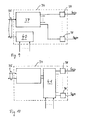
- each actuator unit 14 to a driver circuit 34 which is connected via a bus 35 to a central control circuit 36.
- the drive circuit 34 which supplies switching or control signals S N / 1 ,... S N / M for the valves 33 of the operation unit 14 in response to the control circuit 36 receives control information may include a control information processing circuit 37 (see FIG FIG. 9 ), which is informed by the central control circuit 36, the control data for the corresponding valves 33 for adjusting the required in each of the actuators 12 working pressure.
- the central control circuit 36 supplies only information or data regarding the movement or shape to be taken by the mechanism to the control information processing circuits 37 of the drive circuits 34 of the individual actuator units 14, while the control information processing circuit 37 in each of the actuator units 14 is omitted received data, the corresponding set values to be set for the individual actuators 12 itself determined locally and so the actuators 12 applied via the valves 33 with appropriate working fluid.
- the driver circuit 34 preferably for each valve 33 has a corresponding driver circuit 38 which converts the logic control signals into actuation signals.
- the output signals of the Motion sensor 39 are transmitted back from the driver circuit 34 via a transmission circuit 40 and the bus 35 to the central control circuit 36, which then recalculates the control data for the individual actuators 12 for a control.
- a distributed intelligence or computing capacity is used and only information or data about the motion or position to be taken is provided to the individual drive circuits 34 of the actuators 14, and the control information processing circuits 37 themselves locally determine the corresponding manipulated data for the actuators individual actuating elements 14, which are converted by the valve drivers 38 into corresponding control signals S N / 1 ,... S N / M , it is expedient to provide a regulator circuit 41 in each driver circuit 34, which regulator circuit 41 comprises the setpoint values of the control values and the motion sensors 39 detected actual values of the achieved deformation a changed control value determined for the readjustment.
- a motion sensor for detecting the relative movement of the support plates 11 of an actuator 14 against each other and the curvature of the support structure 10 in the individual actuator units 14 may be provided as movement sensor on the support structure sensors, such as strain gauges.
- strain gauges but also angle encoder, suitably arranged plunger coils or optical position detectors (see FIG. 4 ) be provided.
- a plunger coil 62 is for example in FIG. 5 (a) indicated.
- valves 33 in particular when using stacked piezoelectric elements, as a valve drive are very fast switchable, so that the transmitted for a moving step to be achieved amount can be very small on working medium, which has a corresponding small adjustment step result and thus provides a high setting accuracy.
- worm-shaped mechanism is the supply of the working medium through the continuously deformable support structure 10.
- the support structure 10 itself not only serves as a support or corrugated hose, but also as a pressure hose for supplying the working fluid to the individual valves 33.
- the central line 31. 32 may be performed outside the support structure 10. In FIG. 4 this is shown in an actuator 14 of a worm-shaped mechanism having a spine-like support structure 21, which is constructed in a modular manner.
- the support structure of the actuator 26 'in FIG. 4 a carrier segment 51 with a longitudinal beam 52 and a support plate 53 arranged thereon.
- the longitudinal member 52 has at its end facing away from the support plate 53 end of a hinge member 54, on which a joint bearing 55 is placed, which carries a second support plate 56.
- the joint formed by the articulated member 54 and the pivot bearing 55 may allow rotational movement about the longitudinal axis of the longitudinal member 52 and / or a pivoting or tilting movement relative thereto in one or two degrees of freedom.
- the first support plate 53 has on its side facing away from the longitudinal member 52 as Axialflansch 53 'indicated fastening means for supporting a second support plate 56 of a subsequent or previous actuator unit 26' on.
- First and second connecting means 60 are provided in the first and second support plates to interconnect the individual sections of the bus 35, the working medium supply line 31 and the return or discharge line 32 so that the bus 35 and the conduits 31, 32 extend continuously through the modular worm-shaped mechanism.
- the lines 31, 32 and possibly also the bus 35 as in the embodiment according to FIG. 3 be guided continuously through the mechanism.
- an optical detector 57 which comprises a light source, preferably a laser 58, in particular a laser diode and a position-sensitive photodetector 59.
- Laser 58 and position sensitive Detector 59 are arranged on opposite sides of the first and second support plates 53, 56.
- actuating element 12 which can be connected via a valve 33 to the supply line 31 and the return or discharge line 32, depending on the requirements, two, three or more actuators 12 may be provided.
- first hinge member 24 and hinge bearing 25 are formed so that they only a rotational movement of the upper support plate 56 in FIG. 5 (a) to (d) relative to the longitudinal member 52 of the support segment 51 permits.
- the two actuating elements 12, which are indicated as artificial muscles, are arranged in a V-shaped manner, so that the contraction of the right-hand actuating element 12 in the drawing has carried out a rotation of the upper support plate 56 relative to the lower one in the direction of the arrow d.
- the support plates 56, 53 equipped with bearing elements 53 ', 56', which are shown as holding rods and an actuating element 12 'aufzuspannen therebetween.
- rotational movements and pivoting or tilting movements can be taken over separately from individual actuator units 14.
- rotational movements and pivoting or tilting movements can be taken over separately from individual actuator units 14.
- actuating elements 12 are used in an actuating unit 14, which expand or contract uniformly, an extension or shortening of the actuating unit 14 can also be achieved.
- actuating elements 12 which have been described as pneumatic or hydraulic working elements contracting under pressure, in particular as so-called artificial muscles
- pressure cylinders 12 "as actuating elements as described in US Pat FIG. 7 is shown.
- Such pressure cylinder 12 " depending on the connection of their working chambers with the inlet and outlet lines 31, 32 are movable in one or the other direction, the corresponding support members 11 can actively adjust in both directions against each other.
- actuators 12 provide a return action at pressure relief. But it is also possible that each actuator 12 of an actuator 14, one or more oppositely acting actuators 12 are assigned, as for example in the case of FIG. 3 described actuator 14 is the case.
- Tensile and / or compression spring elements 63 are provided, which internally support these in order to compensate for static forces to be expected in a planned application position of the mechanism, these spring elements can optionally simultaneously serve as return elements for the actuating elements 12.
- Such tension or compression spring elements can also be formed as a surrounding around the worm-shaped mechanism around enveloping spring arrangement.
Landscapes
- Engineering & Computer Science (AREA)
- Robotics (AREA)
- Mechanical Engineering (AREA)
- Health & Medical Sciences (AREA)
- Life Sciences & Earth Sciences (AREA)
- General Health & Medical Sciences (AREA)
- Surgery (AREA)
- Pathology (AREA)
- Heart & Thoracic Surgery (AREA)
- Biophysics (AREA)
- Nuclear Medicine, Radiotherapy & Molecular Imaging (AREA)
- Optics & Photonics (AREA)
- Rheumatology (AREA)
- Radiology & Medical Imaging (AREA)
- Orthopedic Medicine & Surgery (AREA)
- Biomedical Technology (AREA)
- Physics & Mathematics (AREA)
- Medical Informatics (AREA)
- Molecular Biology (AREA)
- Animal Behavior & Ethology (AREA)
- Public Health (AREA)
- Veterinary Medicine (AREA)
- Actuator (AREA)
- Prostheses (AREA)
- Endoscopes (AREA)
- Transmission Devices (AREA)
- Gear Transmission (AREA)
Claims (19)
- Mécanisme vermiforme comprenant :- une structure porteuse (10) s'étendant en direction longitudinale du mécanisme, et- au moins deux unités actionnement (14) agencées les unes derrière les autres en direction longitudinale de la structure porteuse (10), dans lequel-- à chaque unité d'actionnement (14) sont associés deux éléments de soutien (11), qui sont montés sur la structure porteuse (10) à distance l'un de l'autre en direction longitudinale et qui s'étendent transversalement à la direction longitudinale de la structure porteuse (10), et-- chaque unité d'actionnement (14) comprend au moins un élément d'actionnement (12) hydraulique ou pneumatique agencé entre les éléments de soutien (11), qui est raccordé à une conduite d'alimentation centrale (31) pour l'alimentation d'un fluide de travail hydraulique ou pneumatique et au moyen desquels les éléments de soutien (11) sont déplaçables les uns par rapport aux autres, et dans lequel- chacun des éléments d'actionnement (12) est raccordé à la conduite d'alimentation (31),
caractérisé en ce que
ce raccordement a lieu via une valve (33) qui est susceptible d'être pilotée soit individuellement soit par groupe via une conduite centrale (35), et- en ce qu'il est prévu à titre d'éléments d'actionnement (12) des cylindres sous pression qui, selon la liaison de leurs chambres de travail avec des conduites d'amenée et d'évacuation, sont déplaçables dans les deux directions. - Mécanisme vermiforme comprenant :- une structure porteuse (10) s'étendant en direction longitudinale du mécanisme, et- au moins deux unités actionnement (14) agencées les unes derrière les autres en direction longitudinale de la structure porteuse (10), dans lequel-- à chaque unité d'actionnement (14) sont associés deux éléments de soutien (11), qui sont montés sur la structure porteuse (10) à distance l'un de l'autre en direction longitudinale et qui s'étendent transversalement à la direction longitudinale de la structure porteuse (10), et-- chaque unité d'actionnement (14) comprend au moins un élément d'actionnement (12) hydraulique ou pneumatique agencé entre les éléments de soutien (11), qui est raccordé à une conduite d'alimentation centrale (31) pour l'alimentation d'un fluide de travail hydraulique ou pneumatique et au moyen desquels les éléments de soutien (11) sont déplaçables les uns par rapport aux autres, et dans lequel- chacun des éléments d'actionnement (12) est raccordé à la conduite d'alimentation (31),
caractérisé en ce que
ce raccordement a lieu via une valve (33) qui est susceptible d'être pilotée soit individuellement soit par groupe via une conduite centrale (35), et- en ce qu'il est prévu à titre d'éléments d'actionnement (12) des éléments de travail pneumatiques ou hydrauliques qui se contractent sous pression, en particulier ce que l'on appelle des muscles artificiels. - Mécanisme selon la revendication 1, caractérisé en ce que les valves (33) présentent respectivement une première position ouverte pour relier l'élément d'actionnement (12) avec la conduite d'alimentation (31), une position fermée et une seconde position ouverte pour laisser sortir le fluide de travail hors de l'élément d'actionnement (12), dans lequel, dans la seconde position ouverte, les valves (33) relient les éléments d'actionnement (12) avec une conduite de retour ou avec une conduite d'échappement (32).
- Mécanisme selon la revendication 3, caractérisé en ce que les valves (33) sont susceptibles d'être commutées au moyen d'une construction d'éléments piézoélectriques empilés ou au moyen de moteurs piézoélectriques.
- Mécanisme selon l'une des revendications 1 à 4, caractérisé en ce que chaque unité d'actionnement (14) comprend un circuit pilote (34), qui est relié à un circuit de commande central (36) via la conduite centrale (35) et fournit les signaux de commutation pour les valves (33) de l'unité d'actionnement (14) en fonction d'informations de commande reçues par le circuit de commande central (36).
- Mécanisme selon la revendication 5, caractérisé en ce que le circuit pilote (34) comprend un circuit de traitement d'informations de commande (37), qui engendre des signaux de commande pour des circuits de pilotage de valve (38) qui font commuter les valves en fonction des informations de commande reçues.
- Mécanisme selon la revendication 5 ou 6, caractérisé en ce que chaque unité d'actionnement (14) comprend un ou plusieurs capteurs de déplacement (39), dont les signaux de sortie sont détectés par le circuit de pilotage (34)
- Mécanisme selon la revendication 7, caractérisé en ce que le circuit pilote (34) comprend un circuit de transmission (40) pour la transmission des signaux de sortie depuis le ou les capteur(s) de déplacement (39) vers le circuit de commande central (36), ou en ce que le circuit pilote (34) comprend un circuit de régulation (41) auquel sont admis, à titre d'informations de régulation, les informations de commande reçues par le circuit de commande centrale (36) et les signaux de sortie depuis le ou les capteur(s) de déplacement (39), et qui délivre les signaux de commande pour les circuits de pilotage de valve (38) qui font commuter les valves (33), en fonction des informations de régulation.
- Mécanisme selon la revendication 7 8, caractérisé en ce que l'on prévoit un titre de capteur de déplacement (39) une ou plusieurs jauges de mesure d'allongement, qui sont montées sur la structure porteuse (10), en ce que l'on prévoit à titre de capteur de déplacement (39) une ou plusieurs bobines mobiles (62) qui sont agencées entre les éléments de soutien (11) de l'unité d'actionnement (14) de telle façon qu'elles détectent leur mouvement relatif, ou bien en ce que l'on prévoit à titre de capteur de déplacement (39) un détecteur optique de position avec une source de lumière et un récepteur photoélectrique sensible en position, qui sont agencés respectivement sur des éléments, mobiles les uns par rapport aux autres, de l'unité d'actionnement (14), et le détecteur de position délivre un signal de sortie correspondant au mouvement relatif entre ces éléments.
- Mécanisme selon la revendication 2, caractérisé en ce que les éléments d'actionnement (12) délivrent, lors de la décharge de pression, un effet de rappel, et un ou plusieurs éléments d'actionnement (12) à effet opposé est/sont associé(s) à chaque élément d'actionnement (12) d'une unité d'actionnement (14).
- Mécanisme selon la revendication 2, caractérisé en ce qu'un ou plusieurs éléments de rappel (61) est/sont associé(s) aux éléments d'actionnement (12).
- Mécanisme selon l'une des revendications précédentes, caractérisé en ce que le ou les élément(s) d'actionnement (12) dans l'unité d'actionnement (14) est/sont agencé(s) de telle façon qu'ils entraînent, lors d'une activation, une modification de longueur de l'unité d'actionnement (14).
- Mécanisme selon l'une des revendications 1 à 12, caractérisé en ce que, dans une unité d'actionnement (14), deux, trois ou plusieurs éléments d'actionnement (12) sont agencés de telle façon que lors d'une activation correspondante, ils provoquent un basculement défini des deux éléments de soutien (11) l'un par rapport à l'autre dans une direction radiale définie, ou en ce que les éléments d'actionnement (12) sont agencés dans une unité d'actionnement (14) de telle façon que, lors d'une activation, ils provoquent une rotation des deux éléments de soutien (11) autour de la direction longitudinale de la structure porteuse (10).
- Mécanisme selon l'une des revendications précédentes, caractérisé en ce que les éléments de soutien (11) sont réalisés sous forme de disques de soutien qui présentent une traversée pour la conduite centrale (31, 35).
- Mécanisme selon l'une des revendications précédentes, caractérisé en ce que la structure porteuse (10) comprend un support en forme de tube ou de tuyau déformable de manière continue, sur lequel sont fixés les éléments de soutien (11) à des distances axiales définies.
- Mécanisme selon l'une des revendications 1 à 15, caractérisé en ce que la structure porteuse (10) est composée d'une pluralité de segments porteurs (21, 51) de même type, qui sont reliés les uns aux autres à la manière de modules.
- Mécanisme selon la revendication 16, caractérisé en ce que chacune des unités d'actionnement (14) comprend un segment porteur (51), qui inclut une première plaque de soutien (53) qui est reliée fermement à une extrémité d'un support longitudinal (22), et une seconde plaque de soutien (56) qui est maintenue via une liaison articulée (54, 55) en basculement et/ou en pivotement à l'autre extrémité du support longitudinal (52), et la première plaque de soutien (53) comprend, sur son côté détourné du support longitudinal (52), des moyens de fixation (53') pour la fixation d'une seconde plaque de soutien (53) d'un segment porteur voisin, ou en ce que chacune des unités d'actionnement (14) inclut un segment porteur (21) qui comprend une plaque de soutien (23) qui est reliée fermement avec une extrémité d'un support longitudinal (22) et qui porte un palier d'articulation (25) sur son côté détourné du support longitudinal (22), et le support longitudinal (22) porte à son autre extrémité un élément d'articulation (24) correspondant au palier d'articulation (25), de sorte que le support longitudinal (22) d'une unité d'actionnement (14) peut être montée avec possibilité de basculement et/ou de rotation dans le palier d'articulation (25) sur la plaque de soutien (23) de l'unité d'actionnement suivante (14).
- Mécanisme selon l'une des revendications précédentes, caractérisé en ce que, dans une ou plusieurs des unités d'actionnement (14) il est prévu des éléments de ressort en traction et/ou des éléments de ressort en compression qui soutiennent de façon interne ce mécanisme afin de compenser les forces statiques à attendre dans une situation d'application prévue du mécanisme.
- Unité d'actionnement modulaire d'un mécanisme vermiforme, comprenant- une première et une seconde plaque de soutien (53, que 56), qui s'étendent transversalement à la direction longitudinale d'un support longitudinal (52), dans laquelle-- la première plaque de soutien (53) est fermement reliée avec une extrémité du support longitudinal (52),-- la seconde plaque de soutien (56) est maintenue via une liaison articulée (54, 55) avec possibilité de basculement et/ou de rotation sur l'autre extrémité du support longitudinal (52), et-- la première plaque de soutien (53) comprend, sur son côté détourné du support longitudinal (52), des moyens de fixation (53') pour la fixation d'une seconde plaque de soutien (56) d'une unité d'actionnement voisine, et- au moins un élément d'actionnement (12) hydraulique ou pneumatique agencé entre les plaques de soutien (53, 56), qui peut être raccordé à une conduite d'alimentation centrale (31) du mécanisme vermiforme pour l'admission d'un fluide de travail hydraulique ou pneumatique, et au moyen desquels les plaques de soutien (53, 56) sont déplaçable l'une par rapport à l'autre,- dans laquelle chacun des éléments d'actionnement (12) est susceptible d'être raccordé via une valve (33) à la conduite d'alimentation (31), laquelle peut être pilotée via une conduite centrale (35) du mécanisme vermiforme, et
dans laquelle- il est prévu à titre d'éléments d'actionnement (12) des cylindres sous pression qui, selon la liaison de leurs chambres de travail avec des conduites d'amenée et d'évacuation, sont déplaçables dans les deux directions, ou- il est prévu à titre d'éléments d'actionnement (12) des éléments de travail pneumatiques ou hydrauliques qui se contractent sous pression, en particulier ce que l'on appelle des muscles artificiels.
Applications Claiming Priority (2)
| Application Number | Priority Date | Filing Date | Title |
|---|---|---|---|
| DE102006048531 | 2006-10-13 | ||
| PCT/EP2007/008897 WO2008046566A1 (fr) | 2006-10-13 | 2007-10-12 | Mécanisme vermiculaire |
Publications (2)
| Publication Number | Publication Date |
|---|---|
| EP2101963A1 EP2101963A1 (fr) | 2009-09-23 |
| EP2101963B1 true EP2101963B1 (fr) | 2013-06-19 |
Family
ID=38792264
Family Applications (1)
| Application Number | Title | Priority Date | Filing Date |
|---|---|---|---|
| EP07818968.5A Not-in-force EP2101963B1 (fr) | 2006-10-13 | 2007-10-12 | Mécanisme vermiculaire |
Country Status (5)
| Country | Link |
|---|---|
| US (1) | US8201473B2 (fr) |
| EP (1) | EP2101963B1 (fr) |
| JP (1) | JP2010505637A (fr) |
| CN (1) | CN101622107B (fr) |
| WO (1) | WO2008046566A1 (fr) |
Families Citing this family (113)
| Publication number | Priority date | Publication date | Assignee | Title |
|---|---|---|---|---|
| GB0817417D0 (en) * | 2008-09-23 | 2008-10-29 | Shadow Robot Company The Ltd | Robotic muscles |
| CN101653353B (zh) * | 2009-08-28 | 2010-12-01 | 哈尔滨工业大学 | 连续体型半自主式内窥镜机器人 |
| WO2011041909A1 (fr) | 2009-10-07 | 2011-04-14 | Simon Fraser University | Actionneur fluidique et procédé de fabrication |
| EP2335884B1 (fr) * | 2009-12-15 | 2012-09-05 | FESTO AG & Co. KG | Manipulateur pouvant fonctionner de manière fluidique |
| FR2960468B1 (fr) * | 2010-05-31 | 2013-03-29 | Commissariat Energie Atomique | Structure gonflable articulee et bras robotise comportant une telle structure |
| JP5515008B2 (ja) * | 2010-09-30 | 2014-06-11 | 国立大学法人鳥取大学 | 流体による自己推進機能を有するダブルバルーン式内視鏡装置 |
| FR2965501B1 (fr) * | 2010-09-30 | 2013-08-02 | Commissariat Energie Atomique | Structure mecatronique flexible pour un ensemble cinematique, dispositif chirurgical et membre artificiel utilisant cette structure |
| US8899359B1 (en) | 2010-11-05 | 2014-12-02 | The Boeing Company | Locomotion system for robotic snake |
| DE102010056607A1 (de) * | 2010-12-28 | 2012-06-28 | Fraunhofer-Gesellschaft zur Förderung der angewandten Forschung e.V. | Kontinuierliche oder quasikontinuierliche kinematische Kette mit einem sensorischen System |
| KR101271863B1 (ko) * | 2011-05-13 | 2013-06-07 | 주식회사 포스코 | 관절장치 및 이를 사용한 연결장치 |
| DE102011107510B4 (de) * | 2011-07-15 | 2022-07-14 | Deutsches Zentrum für Luft- und Raumfahrt e.V. | Modularer Mehrgelenkmechanismus |
| DE102011108262B4 (de) * | 2011-07-25 | 2015-12-17 | Eisenmann Ag | Vorrichtung zum Lackieren von Fahrzeugkarosserien mit einer Vielzahl von gestaltveranderlichen Armen |
| DE102011121882B4 (de) | 2011-12-21 | 2019-11-28 | Festo Ag & Co. Kg | Arbeitsvorrichtung mit mindestens einem Membranaktor |
| WO2013184192A2 (fr) * | 2012-05-12 | 2013-12-12 | Massachusetts Institute Of Technology | Manipulateur de type continuum actionné par un fluide à changement de phase |
| CZ304220B6 (cs) * | 2012-06-25 | 2014-01-08 | ÄŚVUT v Praze, Fakulta strojnĂ | Manipulátor |
| CZ304673B6 (cs) * | 2012-09-10 | 2014-08-27 | ÄŚVUT v Praze, Fakulta strojnĂ | Způsob a zařízení pro změnu tuhosti sériového nebo paralelního základního pohyblivého mechanismu, zvláště průmyslových robotů a obráběcích strojů |
| US9624911B1 (en) | 2012-10-26 | 2017-04-18 | Sunfolding, Llc | Fluidic solar actuator |
| FR2997888B1 (fr) * | 2012-11-14 | 2015-08-21 | Commissariat Energie Atomique | Bras articule |
| FR2997887B1 (fr) * | 2012-11-14 | 2015-07-10 | Commissariat Energie Atomique | Systeme hexapode |
| CN103085083B (zh) | 2013-01-07 | 2015-06-24 | 汪雯 | 可弯转可伸缩的柔性连续体机械结构 |
| FR3013586B1 (fr) * | 2013-11-27 | 2016-02-05 | Assistive Robotic Technologies | Module articule motorise, articulation comprenant plusieurs modules et exosquelette comprenant plusieurs articulations |
| US9194403B2 (en) * | 2014-02-23 | 2015-11-24 | Dylan Pierre Neyme | Modular hinged joint for use with agonist-antagonist tensile inputs |
| WO2015191122A1 (fr) | 2014-06-13 | 2015-12-17 | Worcester Polytechnic Institute | Actionneurs et procédés d'utilisation |
| DE102014010181B4 (de) * | 2014-07-09 | 2021-03-11 | Schölly Fiberoptic GmbH | Manipulations- und/oder Untersuchungs-Instrument |
| WO2016018254A1 (fr) | 2014-07-29 | 2016-02-04 | Hewlett-Packard Development Company, L.P. | Dispositif connecteur verrouillable |
| CN104440918B (zh) * | 2014-08-18 | 2016-03-02 | 浙江工业大学 | 主动可变刚度长臂式仿生软体机器人 |
| CN104227721B (zh) * | 2014-08-18 | 2015-12-30 | 浙江工业大学 | 仿生软体机器人的可变刚度模块 |
| DE102014113962B3 (de) * | 2014-09-26 | 2015-12-10 | Gottfried Wilhelm Leibniz Universität Hannover | Arbeitsmechanismus |
| KR102209508B1 (ko) * | 2015-01-15 | 2021-02-01 | 한국전자통신연구원 | 인공 근육 |
| MX367676B (es) | 2015-01-30 | 2019-08-30 | Sunfolding Inc | Método y sistema de accionador fluídico. |
| CN104690734B (zh) * | 2015-03-06 | 2016-03-30 | 中国科学院合肥物质科学研究院 | 运行在核聚变舱中的仿蠕虫机器人行走机构及控制方法 |
| CN104816315B (zh) * | 2015-03-18 | 2016-08-24 | 苏州市恒加新精密机械科技有限公司 | 一种纤维收缩控制的仿生机械手臂 |
| GB201504843D0 (en) * | 2015-03-23 | 2015-05-06 | Rolls Royce Plc | Flexible tools and apparatus for machining objects |
| EP3274039B1 (fr) | 2015-03-27 | 2020-04-22 | Project Moray, Inc. | Système d'entraînement de fluide pour une articulation de cathéter et d'autres utilisations |
| CN104706308B (zh) * | 2015-03-30 | 2016-08-17 | 珠海普生医疗科技有限公司 | 一种窥镜用弯曲部结构及窥镜 |
| DE102015004181A1 (de) * | 2015-04-02 | 2016-10-06 | Dieter Mankau | Aktuator |
| DE102015210570A1 (de) * | 2015-06-09 | 2016-12-15 | Kuka Roboter Gmbh | Leitungsführungsvorrichtung eines Industrieroboters |
| CN104924305B (zh) * | 2015-06-19 | 2018-07-06 | 上海交通大学 | 可变形软体球型模块机器人 |
| US11148281B2 (en) * | 2015-07-08 | 2021-10-19 | Stephen Favis | Biomimetic humanoid robotic model, control system, and simulation process |
| WO2017011438A1 (fr) | 2015-07-13 | 2017-01-19 | President And Fellows Of Harvard College | Systèmes de pressurisation et d'échappement répartis pour robots souples |
| US10500373B2 (en) | 2015-12-04 | 2019-12-10 | Project Moray, Inc. | Lateral articulation anchors for catheters and other uses |
| CN108601925B (zh) | 2015-12-04 | 2021-06-29 | 项目莫里股份有限公司 | 用于导管和其他用途的输入和铰接系统 |
| FR3046051B1 (fr) * | 2015-12-24 | 2020-11-13 | Sagem Defense Securite | Module de dos pour une structure d'exosquelette |
| CN106002990B (zh) * | 2016-02-03 | 2018-11-06 | 王远瞻 | 碘动力人工肌肉 |
| WO2017143170A1 (fr) | 2016-02-17 | 2017-08-24 | Keith Phillip Laby | Contraction locale de corps souples par dilatation de ballonnets pour articulation de cathéter par extension-contraction et autres usages |
| US11420021B2 (en) | 2016-03-25 | 2022-08-23 | Project Moray, Inc. | Fluid-actuated displacement for catheters, continuum manipulators, and other uses |
| WO2017165810A1 (fr) | 2016-03-25 | 2017-09-28 | Phillip Laby | Systèmes, dispositifs et procédés de perfectionnement de fonctionnement d'articulation et de déplacement de gaine actionnés par fluide destinés à des cathéters, des manipulateurs de continuum et d'autres utilisations |
| WO2017172902A1 (fr) | 2016-03-29 | 2017-10-05 | Other Lab, Llc | Système d'actionneur robotique fluidique et procédé |
| WO2018064400A1 (fr) * | 2016-09-28 | 2018-04-05 | Project Moray, Inc. | Station de base, station de charge, et/ou serveur pour systèmes de cathéters robotisés et autres utilisations, et dispositifs et systèmes articulés améliorés |
| WO2018064398A1 (fr) | 2016-09-28 | 2018-04-05 | Project Moray, Inc. | Procédés et dispositifs de diagnostic et/ou d'administration de traitement de l'arythmie, et systèmes robotisés pour d'autres utilisations |
| GB201617934D0 (en) * | 2016-10-24 | 2016-12-07 | Univ Dundee | Actuators |
| CN106737570B (zh) * | 2016-11-14 | 2019-01-22 | 杭州电子科技大学 | 液压与仿生肌肉共同驱动的微型机械臂及其驱动方法 |
| WO2018136004A1 (fr) | 2017-01-23 | 2018-07-26 | National University Of Singapore | Actionneur commandé par un fluide et ses applications |
| DE102017203237A1 (de) * | 2017-02-28 | 2018-08-30 | Siemens Aktiengesellschaft | Robotereinheit mit separaten Aktoren und gemeinsamer Gegenaktoreinrichtung für mehrere Glieder |
| KR102329220B1 (ko) * | 2017-03-20 | 2021-11-22 | 한국전자통신연구원 | 인공 근육 |
| KR101867763B1 (ko) * | 2017-04-07 | 2018-06-15 | 고려대학교 산학협력단 | 관절기구의 휨 강성 제어장치 |
| CN106945012B (zh) * | 2017-04-11 | 2023-11-03 | 浙江工业大学 | 一种能自主检测运动位姿的仿生软体机器人 |
| EP3612774A4 (fr) | 2017-04-17 | 2021-01-06 | Sunfolding, Inc. | Système et procédé de circuit d'actionnement pneumatique |
| WO2018200537A1 (fr) | 2017-04-25 | 2018-11-01 | Project Moray, Inc. | Systèmes, dispositifs et méthodes d'articulation de ballonnets supportés par une matrice pour cathéters et autres utilisations |
| CN107243923A (zh) * | 2017-05-24 | 2017-10-13 | 东北大学 | 一种双节McKibben肌肉变刚度软体机器人手臂 |
| CN107309901B (zh) * | 2017-06-23 | 2019-11-15 | 嘉兴学院 | 基于气动肌肉仿人脖子 |
| CN107212924A (zh) * | 2017-07-19 | 2017-09-29 | 连雪芳 | 象鼻仿生超灵巧微创手术机械臂 |
| GB201713277D0 (en) * | 2017-08-18 | 2017-10-04 | Rolls Royce Plc | Hyper-redundant manipulators |
| US10786910B2 (en) * | 2017-08-21 | 2020-09-29 | Massachusetts Institute Of Technology | Extending robotic arm |
| CN107757861A (zh) * | 2017-10-31 | 2018-03-06 | 平顶山学院 | 基于人工纤维肌肉驱动波纹结构的双程主动变形蒙皮 |
| WO2019089709A1 (fr) * | 2017-10-31 | 2019-05-09 | Worcester Polytechnic Institute | Élément de préhension robotique |
| US11865702B2 (en) | 2017-10-31 | 2024-01-09 | Worcester Polytechnic Institute | Robotic gripper member |
| CN108044613A (zh) * | 2017-11-29 | 2018-05-18 | 上海交通大学 | 柔性气动单元与多单元串联机械臂 |
| CN108000503B (zh) * | 2017-12-01 | 2019-12-13 | 嘉兴学院 | 一种基于气动肌肉的多缸体蛇形机器人系统 |
| KR102525009B1 (ko) * | 2017-12-13 | 2023-04-26 | 한국전자통신연구원 | 피드백 제어 가능한 인공 근육 |
| CN108214546A (zh) * | 2017-12-29 | 2018-06-29 | 国网浙江省电力公司绍兴供电公司 | 伸缩式井道探镜 |
| US11318626B1 (en) * | 2018-03-02 | 2022-05-03 | Empower Robotics Corporation | Compliant joint for a robotic arm |
| US11110597B2 (en) * | 2018-04-12 | 2021-09-07 | Arizona Board Of Regents On Behalf Of Arizona State University | Soft poly-limb systems |
| CN108381548A (zh) * | 2018-05-03 | 2018-08-10 | 佛山伊贝尔科技有限公司 | 一种空心玻璃微珠组成的软体机器人 |
| WO2019218157A1 (fr) * | 2018-05-15 | 2019-11-21 | 深圳市亚泰光电技术有限公司 | Procédé d'ajustement de direction d'endoscope et endoscope |
| CN108652570B (zh) * | 2018-05-18 | 2023-06-09 | 清华大学 | 自主推进型软体机器人主体 |
| CN108422441B (zh) * | 2018-05-21 | 2023-05-09 | 南京航空航天大学 | 一种基于压电螺杆泵的水下机械臂及其控制方法 |
| CN108673471B (zh) * | 2018-05-28 | 2021-07-06 | 哈尔滨工业大学 | 可穿戴柔性辅助操作臂 |
| AU2019277145B2 (en) | 2018-05-29 | 2023-06-08 | Sunfolding, Inc. | Tubular fluidic actuator system and method |
| JP7121977B2 (ja) * | 2018-06-01 | 2022-08-19 | 国立大学法人 筑波大学 | アクチュエータ |
| CN108858273A (zh) * | 2018-07-17 | 2018-11-23 | 东北大学 | 一种气动肌肉驱动的六自由度柔顺关节 |
| CN108858177A (zh) * | 2018-08-01 | 2018-11-23 | 佛山市高明曦逻科技有限公司 | 摆动式高精度除尘软体机器人 |
| CN109108953A (zh) * | 2018-09-20 | 2019-01-01 | 上海大学 | 一种无人加油用机械臂系统 |
| DE102018130074B4 (de) * | 2018-11-28 | 2021-07-22 | Gottfried Wilhelm Leibniz Universität Hannover | Schaftmechanismus |
| WO2020163767A1 (fr) * | 2019-02-08 | 2020-08-13 | Worcester Polytechnic Institute | Soupape de régulation de débit de fluide |
| CN109648550A (zh) * | 2019-02-27 | 2019-04-19 | 福州大学 | 一种可变刚度的软体机械臂模块及其控制方法 |
| CN109798275A (zh) * | 2019-02-28 | 2019-05-24 | 重庆科技学院 | 多段式气动组合关节 |
| WO2021065453A1 (fr) * | 2019-09-30 | 2021-04-08 | アイシン・エィ・ダブリュ株式会社 | Robot et dispositif d'alimentation en liquide |
| EP3822046B1 (fr) * | 2019-11-12 | 2024-05-08 | Festo SE & Co. KG | Structure de robot |
| CN111360801B (zh) * | 2020-03-20 | 2021-04-27 | 哈尔滨工程大学 | 基于电磁人工肌肉的仿鳗鱼机器人及其工作方法 |
| EP4169157A1 (fr) | 2020-06-22 | 2023-04-26 | Sunfolding, Inc. | Systèmes et procédés de verrouillage, d'amortissement et d'actionnement pour suiveurs solaires |
| CN111761606B (zh) * | 2020-07-08 | 2021-10-22 | 北京卫星环境工程研究所 | 基于新型气动肌肉的气动软体触手机器人 |
| CN112336297B (zh) * | 2020-10-31 | 2022-06-07 | 同济大学 | 体内导入装置的控制方法、系统和计算机可读存储介质 |
| CN112428298B (zh) * | 2020-11-17 | 2022-03-15 | 中国科学院宁波材料技术与工程研究所 | 一种软体机器人臂及其控制系统 |
| CN112692872B (zh) * | 2020-12-21 | 2022-07-22 | 哈尔滨工业大学 | 一种基于气动的连续可变刚度脊柱关节 |
| TWI777396B (zh) * | 2021-01-29 | 2022-09-11 | 施長碧 | 新型內視鏡 |
| CN112828926A (zh) * | 2021-02-05 | 2021-05-25 | 纪新刚 | 一种流体柔性机械手及其组件 |
| US12378979B2 (en) | 2021-03-24 | 2025-08-05 | Adaract Technologies, Ltd. | Dynamic recruitment modulation in systems utilizing variable recruitment |
| US11719263B2 (en) * | 2021-03-24 | 2023-08-08 | Adaract Technologies, Ltd. | Variable recruitment actuator systems and related methods |
| JP2022155599A (ja) * | 2021-03-31 | 2022-10-14 | 株式会社アイシン | ロボット装置 |
| CN113290550A (zh) * | 2021-05-26 | 2021-08-24 | 北京理工大学 | 一种基于Mckibben型气动人工肌肉驱动的可伸缩仿生象鼻装置 |
| CN114603597A (zh) * | 2022-03-04 | 2022-06-10 | 北京软体机器人科技有限公司 | 一种刚软耦合机械臂 |
| CN114505883A (zh) * | 2022-03-23 | 2022-05-17 | 北京信息科技大学 | 一种面向拉索式机器人的液态金属辅助万向节及设计方法 |
| CN115042164A (zh) * | 2022-06-01 | 2022-09-13 | 中国科学院深圳先进技术研究院 | 一种软体机器人的模块单元及软体机器人 |
| CN115091450B (zh) * | 2022-07-15 | 2023-09-01 | 万勋科技(深圳)有限公司 | 柔性机械臂及机器人 |
| CN115646696B (zh) * | 2022-09-09 | 2025-09-12 | 厦门永东丰机器人科技有限公司 | 一种多维度自动喷涂机器人 |
| US20240142194A1 (en) * | 2022-10-26 | 2024-05-02 | Ryan Thomas Kinback | Energy Bow Actuator and Launcher |
| CN116277057B (zh) * | 2023-03-02 | 2026-03-13 | 西南科技大学 | 稳压驱动双稳态致动器 |
| CN116619399B (zh) * | 2023-03-31 | 2026-03-06 | 中国科学院武汉岩土力学研究所 | 一种仿蛇形机器人及基于仿蛇形机器人的洞穴探测方法 |
| US20250032939A1 (en) * | 2023-07-24 | 2025-01-30 | Universal City Studios Llc | System and method to simulate anatomical features in an entertainment figure |
| CN117162139B (zh) * | 2023-09-18 | 2026-02-17 | 宁波凯荣新能源有限公司 | 一种气液可逆式柔性机械臂 |
| WO2025187574A1 (fr) * | 2024-03-08 | 2025-09-12 | オリンパス株式会社 | Système médical et dispositif de suture |
| CN118288313A (zh) * | 2024-05-15 | 2024-07-05 | 四川大学 | 柔性自适应力控接触装置 |
Family Cites Families (23)
| Publication number | Priority date | Publication date | Assignee | Title |
|---|---|---|---|---|
| US3284964A (en) * | 1964-03-26 | 1966-11-15 | Saito Norio | Flexible beam structures |
| SE419421B (sv) | 1979-03-16 | 1981-08-03 | Ove Larson | Bojlig arm i synnerhet robotarm |
| JPS5937080A (ja) * | 1982-08-17 | 1984-02-29 | ダイキン工業株式会社 | ハンドリング装置の液圧回路 |
| JPS6150794A (ja) * | 1984-08-14 | 1986-03-13 | 三菱重工業株式会社 | 多関節ア−ム |
| US4784042A (en) * | 1986-02-12 | 1988-11-15 | Nathaniel A. Hardin | Method and system employing strings of opposed gaseous-fluid inflatable tension actuators in jointed arms, legs, beams and columns for controlling their movements |
| US4765795A (en) * | 1986-06-10 | 1988-08-23 | Lord Corporation | Object manipulator |
| JPH0740088B2 (ja) * | 1987-02-06 | 1995-05-01 | オリンパス光学工業株式会社 | 内視鏡 |
| US5251538A (en) * | 1991-08-21 | 1993-10-12 | Battelle Memorial Institute | Prehensile apparatus |
| JPH05184526A (ja) * | 1991-09-17 | 1993-07-27 | Olympus Optical Co Ltd | 可撓管の湾曲機構 |
| DE4133605C2 (de) * | 1991-10-10 | 1994-05-11 | Siemens Ag | Flexibler Roboterarm |
| JPH05293787A (ja) * | 1992-04-16 | 1993-11-09 | Ishikawajima Harima Heavy Ind Co Ltd | 3次元屈曲型ロボットア−ム |
| US5337732A (en) * | 1992-09-16 | 1994-08-16 | Cedars-Sinai Medical Center | Robotic endoscopy |
| DE4240435A1 (de) | 1992-11-13 | 1994-05-19 | D T I Dr Trippe Ingenieurgesel | Bewegbarer, in seiner Raumform veränderbarer Arm, insbesondere als Träger von Werkzeugen, Sichtgeräten oder dergleichen |
| US5386741A (en) * | 1993-06-07 | 1995-02-07 | Rennex; Brian G. | Robotic snake |
| DE4408730A1 (de) * | 1994-03-15 | 1995-09-21 | Daum Gmbh | Steuerbarer Instrumentenkanal |
| JP2886452B2 (ja) * | 1994-05-20 | 1999-04-26 | 畑村 洋太郎 | 変形量検出手段付き直線運動装置 |
| DE19833340A1 (de) * | 1998-07-24 | 2000-02-10 | Karlsruhe Forschzent | Wurmförmiger Arbeitsmechanismus |
| JP2001038598A (ja) * | 1999-07-26 | 2001-02-13 | Prima Meat Packers Ltd | 自動研磨機 |
| JP2001310281A (ja) * | 2000-04-27 | 2001-11-06 | Sony Corp | コンフィギュレーション取得方法並びに状態検出方法 |
| JP2001356279A (ja) * | 2000-06-14 | 2001-12-26 | Toshiba Plant Kensetsu Co Ltd | カメラケーブルの姿勢操作装置および操作方法 |
| US6772673B2 (en) * | 2001-12-13 | 2004-08-10 | Seiko Epson Corporation | Flexible actuator |
| CN1251841C (zh) * | 2002-11-06 | 2006-04-19 | 中国科学院沈阳自动化研究所 | 一种模块化可变结构蛇形机器人 |
| JP4505299B2 (ja) * | 2004-06-04 | 2010-07-21 | パナソニック株式会社 | 弾性体アクチュエータ駆動型可動機構の制御装置及び制御方法 |
-
2007
- 2007-10-12 JP JP2009531785A patent/JP2010505637A/ja active Pending
- 2007-10-12 CN CN200780046230.XA patent/CN101622107B/zh not_active Expired - Fee Related
- 2007-10-12 US US12/445,426 patent/US8201473B2/en not_active Expired - Fee Related
- 2007-10-12 WO PCT/EP2007/008897 patent/WO2008046566A1/fr not_active Ceased
- 2007-10-12 EP EP07818968.5A patent/EP2101963B1/fr not_active Not-in-force
Also Published As
| Publication number | Publication date |
|---|---|
| EP2101963A1 (fr) | 2009-09-23 |
| CN101622107A (zh) | 2010-01-06 |
| JP2010505637A (ja) | 2010-02-25 |
| CN101622107B (zh) | 2012-09-19 |
| WO2008046566A8 (fr) | 2009-06-04 |
| WO2008046566A1 (fr) | 2008-04-24 |
| US20090314119A1 (en) | 2009-12-24 |
| US8201473B2 (en) | 2012-06-19 |
Similar Documents
| Publication | Publication Date | Title |
|---|---|---|
| EP2101963A1 (fr) | Mécanisme vermiculaire | |
| EP2335884B1 (fr) | Manipulateur pouvant fonctionner de manière fluidique | |
| EP2952302B1 (fr) | Dispositif de retenue ou de préhension | |
| EP2903789B1 (fr) | Robot industriel | |
| EP2498956B1 (fr) | Unité d'équilibrage à fonctionnement fluidique | |
| EP1182485B1 (fr) | Dispositif de réglage de la position relative de deux éléments | |
| DE10140608A1 (de) | Vorrichtung zur Justage eines optischen Elements | |
| EP1820610B1 (fr) | Main de robot | |
| EP0791438A2 (fr) | Dispositif pour le déplacement d'un corps dans l'espace | |
| DE102016101812B4 (de) | Auslenkelement | |
| DE102011109786B4 (de) | Antriebsvorrichtung | |
| DE202016106705U1 (de) | Aktuator | |
| DE102005056846B4 (de) | Linearantrieb mit einem mit einem Medium befüllbaren Aktor | |
| DE1531252C3 (de) | Manipulatorarm | |
| DE102004046531B4 (de) | Spiegelhalterungseinrichtung und optische Vorrichtung, die diese verwendet | |
| EP0683016A1 (fr) | Système porteur pour bras flexible dont les éléments sont de plaçables à volonté dans l'espace | |
| DE20309196U1 (de) | Schwenkvorrichtung und Schwenksystem | |
| DE102014118459A1 (de) | Einrichtung zum Vortrieb von Inspektions- und/oder Reinigungssystemen | |
| DE20107329U1 (de) | Positioniervorrichtung zur Positionierung eines Werkzeuges | |
| DE102010025392A1 (de) | Handhabungssystem zur Aufnahme von wenigstens zwei räumlich geordneten Werkstücken und Abgeben der Werkstücke mit einer geordnet veränderten Relativlage der Werkstücke | |
| WO1996035877A1 (fr) | Element d'actionnement fluidique | |
| EP2233256A1 (fr) | Dispositif d'entraînement | |
| DE102013206696B4 (de) | Vorrichtung und ein Verfahren zur Steuerung einer Handhabungseinrichtung | |
| AT503883B1 (de) | Antrieb für eine parallelkinematische mechanische anordnung | |
| DE102007007165B4 (de) | Maschine |
Legal Events
| Date | Code | Title | Description |
|---|---|---|---|
| PUAI | Public reference made under article 153(3) epc to a published international application that has entered the european phase |
Free format text: ORIGINAL CODE: 0009012 |
|
| 17P | Request for examination filed |
Effective date: 20090508 |
|
| AK | Designated contracting states |
Kind code of ref document: A1 Designated state(s): AT BE BG CH CY CZ DE DK EE ES FI FR GB GR HU IE IS IT LI LT LU LV MC MT NL PL PT RO SE SI SK TR |
|
| 17Q | First examination report despatched |
Effective date: 20091007 |
|
| DAX | Request for extension of the european patent (deleted) | ||
| GRAP | Despatch of communication of intention to grant a patent |
Free format text: ORIGINAL CODE: EPIDOSNIGR1 |
|
| RIC1 | Information provided on ipc code assigned before grant |
Ipc: B25J 19/00 20060101ALI20121212BHEP Ipc: A61B 1/00 20060101ALI20121212BHEP Ipc: B25J 9/10 20060101AFI20121212BHEP Ipc: B25J 9/06 20060101ALI20121212BHEP Ipc: B25J 18/06 20060101ALI20121212BHEP Ipc: B25J 9/14 20060101ALI20121212BHEP |
|
| GRAS | Grant fee paid |
Free format text: ORIGINAL CODE: EPIDOSNIGR3 |
|
| GRAA | (expected) grant |
Free format text: ORIGINAL CODE: 0009210 |
|
| AK | Designated contracting states |
Kind code of ref document: B1 Designated state(s): AT BE BG CH CY CZ DE DK EE ES FI FR GB GR HU IE IS IT LI LT LU LV MC MT NL PL PT RO SE SI SK TR |
|
| REG | Reference to a national code |
Ref country code: GB Ref legal event code: FG4D Free format text: NOT ENGLISH |
|
| REG | Reference to a national code |
Ref country code: CH Ref legal event code: EP |
|
| REG | Reference to a national code |
Ref country code: AT Ref legal event code: REF Ref document number: 617379 Country of ref document: AT Kind code of ref document: T Effective date: 20130715 |
|
| REG | Reference to a national code |
Ref country code: IE Ref legal event code: FG4D Free format text: LANGUAGE OF EP DOCUMENT: GERMAN |
|
| REG | Reference to a national code |
Ref country code: DE Ref legal event code: R096 Ref document number: 502007011932 Country of ref document: DE Effective date: 20130814 |
|
| PG25 | Lapsed in a contracting state [announced via postgrant information from national office to epo] |
Ref country code: ES Free format text: LAPSE BECAUSE OF FAILURE TO SUBMIT A TRANSLATION OF THE DESCRIPTION OR TO PAY THE FEE WITHIN THE PRESCRIBED TIME-LIMIT Effective date: 20130930 Ref country code: SI Free format text: LAPSE BECAUSE OF FAILURE TO SUBMIT A TRANSLATION OF THE DESCRIPTION OR TO PAY THE FEE WITHIN THE PRESCRIBED TIME-LIMIT Effective date: 20130619 Ref country code: FI Free format text: LAPSE BECAUSE OF FAILURE TO SUBMIT A TRANSLATION OF THE DESCRIPTION OR TO PAY THE FEE WITHIN THE PRESCRIBED TIME-LIMIT Effective date: 20130619 Ref country code: GR Free format text: LAPSE BECAUSE OF FAILURE TO SUBMIT A TRANSLATION OF THE DESCRIPTION OR TO PAY THE FEE WITHIN THE PRESCRIBED TIME-LIMIT Effective date: 20130920 Ref country code: LT Free format text: LAPSE BECAUSE OF FAILURE TO SUBMIT A TRANSLATION OF THE DESCRIPTION OR TO PAY THE FEE WITHIN THE PRESCRIBED TIME-LIMIT Effective date: 20130619 Ref country code: SE Free format text: LAPSE BECAUSE OF FAILURE TO SUBMIT A TRANSLATION OF THE DESCRIPTION OR TO PAY THE FEE WITHIN THE PRESCRIBED TIME-LIMIT Effective date: 20130619 |
|
| REG | Reference to a national code |
Ref country code: LT Ref legal event code: MG4D |
|
| PG25 | Lapsed in a contracting state [announced via postgrant information from national office to epo] |
Ref country code: BG Free format text: LAPSE BECAUSE OF FAILURE TO SUBMIT A TRANSLATION OF THE DESCRIPTION OR TO PAY THE FEE WITHIN THE PRESCRIBED TIME-LIMIT Effective date: 20130919 |
|
| REG | Reference to a national code |
Ref country code: NL Ref legal event code: VDEP Effective date: 20130619 |
|
| PG25 | Lapsed in a contracting state [announced via postgrant information from national office to epo] |
Ref country code: LV Free format text: LAPSE BECAUSE OF FAILURE TO SUBMIT A TRANSLATION OF THE DESCRIPTION OR TO PAY THE FEE WITHIN THE PRESCRIBED TIME-LIMIT Effective date: 20130619 |
|
| PG25 | Lapsed in a contracting state [announced via postgrant information from national office to epo] |
Ref country code: PT Free format text: LAPSE BECAUSE OF FAILURE TO SUBMIT A TRANSLATION OF THE DESCRIPTION OR TO PAY THE FEE WITHIN THE PRESCRIBED TIME-LIMIT Effective date: 20131021 Ref country code: SK Free format text: LAPSE BECAUSE OF FAILURE TO SUBMIT A TRANSLATION OF THE DESCRIPTION OR TO PAY THE FEE WITHIN THE PRESCRIBED TIME-LIMIT Effective date: 20130619 Ref country code: IS Free format text: LAPSE BECAUSE OF FAILURE TO SUBMIT A TRANSLATION OF THE DESCRIPTION OR TO PAY THE FEE WITHIN THE PRESCRIBED TIME-LIMIT Effective date: 20131019 Ref country code: EE Free format text: LAPSE BECAUSE OF FAILURE TO SUBMIT A TRANSLATION OF THE DESCRIPTION OR TO PAY THE FEE WITHIN THE PRESCRIBED TIME-LIMIT Effective date: 20130619 Ref country code: CZ Free format text: LAPSE BECAUSE OF FAILURE TO SUBMIT A TRANSLATION OF THE DESCRIPTION OR TO PAY THE FEE WITHIN THE PRESCRIBED TIME-LIMIT Effective date: 20130619 Ref country code: CY Free format text: LAPSE BECAUSE OF FAILURE TO SUBMIT A TRANSLATION OF THE DESCRIPTION OR TO PAY THE FEE WITHIN THE PRESCRIBED TIME-LIMIT Effective date: 20130807 |
|
| PG25 | Lapsed in a contracting state [announced via postgrant information from national office to epo] |
Ref country code: NL Free format text: LAPSE BECAUSE OF FAILURE TO SUBMIT A TRANSLATION OF THE DESCRIPTION OR TO PAY THE FEE WITHIN THE PRESCRIBED TIME-LIMIT Effective date: 20130619 Ref country code: PL Free format text: LAPSE BECAUSE OF FAILURE TO SUBMIT A TRANSLATION OF THE DESCRIPTION OR TO PAY THE FEE WITHIN THE PRESCRIBED TIME-LIMIT Effective date: 20130619 Ref country code: RO Free format text: LAPSE BECAUSE OF FAILURE TO SUBMIT A TRANSLATION OF THE DESCRIPTION OR TO PAY THE FEE WITHIN THE PRESCRIBED TIME-LIMIT Effective date: 20130619 |
|
| PG25 | Lapsed in a contracting state [announced via postgrant information from national office to epo] |
Ref country code: CY Free format text: LAPSE BECAUSE OF FAILURE TO SUBMIT A TRANSLATION OF THE DESCRIPTION OR TO PAY THE FEE WITHIN THE PRESCRIBED TIME-LIMIT Effective date: 20130619 |
|
| PLBE | No opposition filed within time limit |
Free format text: ORIGINAL CODE: 0009261 |
|
| STAA | Information on the status of an ep patent application or granted ep patent |
Free format text: STATUS: NO OPPOSITION FILED WITHIN TIME LIMIT |
|
| BERE | Be: lapsed |
Owner name: ROBOTICS TECHNOLOGY LEADERS G.M.B.H. Effective date: 20131031 |
|
| PG25 | Lapsed in a contracting state [announced via postgrant information from national office to epo] |
Ref country code: DK Free format text: LAPSE BECAUSE OF FAILURE TO SUBMIT A TRANSLATION OF THE DESCRIPTION OR TO PAY THE FEE WITHIN THE PRESCRIBED TIME-LIMIT Effective date: 20130619 |
|
| 26N | No opposition filed |
Effective date: 20140320 |
|
| PG25 | Lapsed in a contracting state [announced via postgrant information from national office to epo] |
Ref country code: MC Free format text: LAPSE BECAUSE OF FAILURE TO SUBMIT A TRANSLATION OF THE DESCRIPTION OR TO PAY THE FEE WITHIN THE PRESCRIBED TIME-LIMIT Effective date: 20130619 Ref country code: IT Free format text: LAPSE BECAUSE OF FAILURE TO SUBMIT A TRANSLATION OF THE DESCRIPTION OR TO PAY THE FEE WITHIN THE PRESCRIBED TIME-LIMIT Effective date: 20130619 |
|
| REG | Reference to a national code |
Ref country code: CH Ref legal event code: PL |
|
| REG | Reference to a national code |
Ref country code: DE Ref legal event code: R097 Ref document number: 502007011932 Country of ref document: DE Effective date: 20140320 |
|
| REG | Reference to a national code |
Ref country code: IE Ref legal event code: MM4A |
|
| PG25 | Lapsed in a contracting state [announced via postgrant information from national office to epo] |
Ref country code: LI Free format text: LAPSE BECAUSE OF NON-PAYMENT OF DUE FEES Effective date: 20131031 Ref country code: CH Free format text: LAPSE BECAUSE OF NON-PAYMENT OF DUE FEES Effective date: 20131031 |
|
| PG25 | Lapsed in a contracting state [announced via postgrant information from national office to epo] |
Ref country code: BE Free format text: LAPSE BECAUSE OF NON-PAYMENT OF DUE FEES Effective date: 20131031 |
|
| PG25 | Lapsed in a contracting state [announced via postgrant information from national office to epo] |
Ref country code: IE Free format text: LAPSE BECAUSE OF NON-PAYMENT OF DUE FEES Effective date: 20131012 |
|
| REG | Reference to a national code |
Ref country code: AT Ref legal event code: MM01 Ref document number: 617379 Country of ref document: AT Kind code of ref document: T Effective date: 20131012 |
|
| PG25 | Lapsed in a contracting state [announced via postgrant information from national office to epo] |
Ref country code: AT Free format text: LAPSE BECAUSE OF NON-PAYMENT OF DUE FEES Effective date: 20131012 |
|
| PG25 | Lapsed in a contracting state [announced via postgrant information from national office to epo] |
Ref country code: TR Free format text: LAPSE BECAUSE OF FAILURE TO SUBMIT A TRANSLATION OF THE DESCRIPTION OR TO PAY THE FEE WITHIN THE PRESCRIBED TIME-LIMIT Effective date: 20130619 |
|
| PG25 | Lapsed in a contracting state [announced via postgrant information from national office to epo] |
Ref country code: LU Free format text: LAPSE BECAUSE OF NON-PAYMENT OF DUE FEES Effective date: 20131012 Ref country code: HU Free format text: LAPSE BECAUSE OF FAILURE TO SUBMIT A TRANSLATION OF THE DESCRIPTION OR TO PAY THE FEE WITHIN THE PRESCRIBED TIME-LIMIT; INVALID AB INITIO Effective date: 20071012 |
|
| PG25 | Lapsed in a contracting state [announced via postgrant information from national office to epo] |
Ref country code: MT Free format text: LAPSE BECAUSE OF FAILURE TO SUBMIT A TRANSLATION OF THE DESCRIPTION OR TO PAY THE FEE WITHIN THE PRESCRIBED TIME-LIMIT Effective date: 20130619 |
|
| REG | Reference to a national code |
Ref country code: FR Ref legal event code: PLFP Year of fee payment: 9 |
|
| PGFP | Annual fee paid to national office [announced via postgrant information from national office to epo] |
Ref country code: GB Payment date: 20151026 Year of fee payment: 9 Ref country code: DE Payment date: 20151030 Year of fee payment: 9 |
|
| PGFP | Annual fee paid to national office [announced via postgrant information from national office to epo] |
Ref country code: FR Payment date: 20151026 Year of fee payment: 9 |
|
| REG | Reference to a national code |
Ref country code: DE Ref legal event code: R119 Ref document number: 502007011932 Country of ref document: DE |
|
| GBPC | Gb: european patent ceased through non-payment of renewal fee |
Effective date: 20161012 |
|
| REG | Reference to a national code |
Ref country code: FR Ref legal event code: ST Effective date: 20170630 |
|
| PG25 | Lapsed in a contracting state [announced via postgrant information from national office to epo] |
Ref country code: DE Free format text: LAPSE BECAUSE OF NON-PAYMENT OF DUE FEES Effective date: 20170503 Ref country code: GB Free format text: LAPSE BECAUSE OF NON-PAYMENT OF DUE FEES Effective date: 20161012 Ref country code: FR Free format text: LAPSE BECAUSE OF NON-PAYMENT OF DUE FEES Effective date: 20161102 |