EP2102026B1 - Kraftstoffbehälter aus thermoplastischem kunststoff mit funktionseinbauten zur be- und entlüftung, zur kraftstoffentnahme oder dergleichen - Google Patents
Kraftstoffbehälter aus thermoplastischem kunststoff mit funktionseinbauten zur be- und entlüftung, zur kraftstoffentnahme oder dergleichen Download PDFInfo
- Publication number
- EP2102026B1 EP2102026B1 EP20070819883 EP07819883A EP2102026B1 EP 2102026 B1 EP2102026 B1 EP 2102026B1 EP 20070819883 EP20070819883 EP 20070819883 EP 07819883 A EP07819883 A EP 07819883A EP 2102026 B1 EP2102026 B1 EP 2102026B1
- Authority
- EP
- European Patent Office
- Prior art keywords
- wall
- tank
- container
- fuel
- fuel tank
- Prior art date
- Legal status (The legal status is an assumption and is not a legal conclusion. Google has not performed a legal analysis and makes no representation as to the accuracy of the status listed.)
- Not-in-force
Links
- 239000002828 fuel tank Substances 0.000 title claims description 41
- 239000000446 fuel Substances 0.000 title claims description 13
- 238000009423 ventilation Methods 0.000 title claims description 4
- 229920001169 thermoplastic Polymers 0.000 title claims description 3
- 239000004416 thermosoftening plastic Substances 0.000 title claims description 3
- 229920002994 synthetic fiber Polymers 0.000 title claims 2
- 238000005304 joining Methods 0.000 claims description 10
- 238000011049 filling Methods 0.000 claims description 2
- 230000015572 biosynthetic process Effects 0.000 description 9
- 239000004033 plastic Substances 0.000 description 9
- 229920003023 plastic Polymers 0.000 description 9
- 239000000463 material Substances 0.000 description 6
- 238000003466 welding Methods 0.000 description 5
- 238000001816 cooling Methods 0.000 description 4
- 238000001125 extrusion Methods 0.000 description 4
- 239000012815 thermoplastic material Substances 0.000 description 4
- 238000002485 combustion reaction Methods 0.000 description 3
- 238000000034 method Methods 0.000 description 3
- 239000004831 Hot glue Substances 0.000 description 2
- 238000013459 approach Methods 0.000 description 2
- 238000000071 blow moulding Methods 0.000 description 2
- 239000007788 liquid Substances 0.000 description 2
- 238000004519 manufacturing process Methods 0.000 description 2
- 230000001133 acceleration Effects 0.000 description 1
- 238000009825 accumulation Methods 0.000 description 1
- 239000000853 adhesive Substances 0.000 description 1
- 230000001070 adhesive effect Effects 0.000 description 1
- 230000004888 barrier function Effects 0.000 description 1
- 238000007664 blowing Methods 0.000 description 1
- 239000000969 carrier Substances 0.000 description 1
- 230000001419 dependent effect Effects 0.000 description 1
- 230000000694 effects Effects 0.000 description 1
- 238000000605 extraction Methods 0.000 description 1
- 239000000945 filler Substances 0.000 description 1
- 229930195733 hydrocarbon Natural products 0.000 description 1
- 150000002430 hydrocarbons Chemical class 0.000 description 1
- 230000001771 impaired effect Effects 0.000 description 1
- 238000001746 injection moulding Methods 0.000 description 1
- 238000009434 installation Methods 0.000 description 1
- 238000002156 mixing Methods 0.000 description 1
- 239000002991 molded plastic Substances 0.000 description 1
- 238000000465 moulding Methods 0.000 description 1
- 210000002445 nipple Anatomy 0.000 description 1
- 230000002093 peripheral effect Effects 0.000 description 1
- 238000003856 thermoforming Methods 0.000 description 1
- XLYOFNOQVPJJNP-UHFFFAOYSA-N water Substances O XLYOFNOQVPJJNP-UHFFFAOYSA-N 0.000 description 1
Images

Classifications
-
- B—PERFORMING OPERATIONS; TRANSPORTING
- B60—VEHICLES IN GENERAL
- B60K—ARRANGEMENT OR MOUNTING OF PROPULSION UNITS OR OF TRANSMISSIONS IN VEHICLES; ARRANGEMENT OR MOUNTING OF PLURAL DIVERSE PRIME-MOVERS IN VEHICLES; AUXILIARY DRIVES FOR VEHICLES; INSTRUMENTATION OR DASHBOARDS FOR VEHICLES; ARRANGEMENTS IN CONNECTION WITH COOLING, AIR INTAKE, GAS EXHAUST OR FUEL SUPPLY OF PROPULSION UNITS IN VEHICLES
- B60K15/00—Arrangement in connection with fuel supply of combustion engines or other fuel consuming energy converters, e.g. fuel cells; Mounting or construction of fuel tanks
- B60K15/03—Fuel tanks
- B60K15/03177—Fuel tanks made of non-metallic material, e.g. plastics, or of a combination of non-metallic and metallic material
-
- B—PERFORMING OPERATIONS; TRANSPORTING
- B29—WORKING OF PLASTICS; WORKING OF SUBSTANCES IN A PLASTIC STATE IN GENERAL
- B29C—SHAPING OR JOINING OF PLASTICS; SHAPING OF MATERIAL IN A PLASTIC STATE, NOT OTHERWISE PROVIDED FOR; AFTER-TREATMENT OF THE SHAPED PRODUCTS, e.g. REPAIRING
- B29C49/00—Blow-moulding, i.e. blowing a preform or parison to a desired shape within a mould; Apparatus therefor
- B29C49/20—Blow-moulding, i.e. blowing a preform or parison to a desired shape within a mould; Apparatus therefor of articles having inserts or reinforcements ; Handling of inserts or reinforcements
-
- B—PERFORMING OPERATIONS; TRANSPORTING
- B29—WORKING OF PLASTICS; WORKING OF SUBSTANCES IN A PLASTIC STATE IN GENERAL
- B29C—SHAPING OR JOINING OF PLASTICS; SHAPING OF MATERIAL IN A PLASTIC STATE, NOT OTHERWISE PROVIDED FOR; AFTER-TREATMENT OF THE SHAPED PRODUCTS, e.g. REPAIRING
- B29C49/00—Blow-moulding, i.e. blowing a preform or parison to a desired shape within a mould; Apparatus therefor
- B29C49/22—Blow-moulding, i.e. blowing a preform or parison to a desired shape within a mould; Apparatus therefor using multilayered preforms or parisons
-
- B—PERFORMING OPERATIONS; TRANSPORTING
- B29—WORKING OF PLASTICS; WORKING OF SUBSTANCES IN A PLASTIC STATE IN GENERAL
- B29C—SHAPING OR JOINING OF PLASTICS; SHAPING OF MATERIAL IN A PLASTIC STATE, NOT OTHERWISE PROVIDED FOR; AFTER-TREATMENT OF THE SHAPED PRODUCTS, e.g. REPAIRING
- B29C51/00—Shaping by thermoforming, i.e. shaping sheets or sheet like preforms after heating, e.g. shaping sheets in matched moulds or by deep-drawing; Apparatus therefor
- B29C51/26—Component parts, details or accessories; Auxiliary operations
- B29C51/266—Auxiliary operations after the thermoforming operation
- B29C51/267—Two sheets being thermoformed in separate mould parts and joined together while still in the mould
-
- B—PERFORMING OPERATIONS; TRANSPORTING
- B29—WORKING OF PLASTICS; WORKING OF SUBSTANCES IN A PLASTIC STATE IN GENERAL
- B29C—SHAPING OR JOINING OF PLASTICS; SHAPING OF MATERIAL IN A PLASTIC STATE, NOT OTHERWISE PROVIDED FOR; AFTER-TREATMENT OF THE SHAPED PRODUCTS, e.g. REPAIRING
- B29C65/00—Joining or sealing of preformed parts, e.g. welding of plastics materials; Apparatus therefor
- B29C65/02—Joining or sealing of preformed parts, e.g. welding of plastics materials; Apparatus therefor by heating, with or without pressure
- B29C65/022—Particular heating or welding methods not otherwise provided for
- B29C65/028—Particular heating or welding methods not otherwise provided for making use of inherent heat, i.e. the heat for the joining comes from the moulding process of one of the parts to be joined
-
- B—PERFORMING OPERATIONS; TRANSPORTING
- B29—WORKING OF PLASTICS; WORKING OF SUBSTANCES IN A PLASTIC STATE IN GENERAL
- B29C—SHAPING OR JOINING OF PLASTICS; SHAPING OF MATERIAL IN A PLASTIC STATE, NOT OTHERWISE PROVIDED FOR; AFTER-TREATMENT OF THE SHAPED PRODUCTS, e.g. REPAIRING
- B29C65/00—Joining or sealing of preformed parts, e.g. welding of plastics materials; Apparatus therefor
- B29C65/48—Joining or sealing of preformed parts, e.g. welding of plastics materials; Apparatus therefor using adhesives, i.e. using supplementary joining material; solvent bonding
- B29C65/4805—Joining or sealing of preformed parts, e.g. welding of plastics materials; Apparatus therefor using adhesives, i.e. using supplementary joining material; solvent bonding characterised by the type of adhesives
- B29C65/481—Non-reactive adhesives, e.g. physically hardening adhesives
- B29C65/4815—Hot melt adhesives, e.g. thermoplastic adhesives
-
- B—PERFORMING OPERATIONS; TRANSPORTING
- B29—WORKING OF PLASTICS; WORKING OF SUBSTANCES IN A PLASTIC STATE IN GENERAL
- B29C—SHAPING OR JOINING OF PLASTICS; SHAPING OF MATERIAL IN A PLASTIC STATE, NOT OTHERWISE PROVIDED FOR; AFTER-TREATMENT OF THE SHAPED PRODUCTS, e.g. REPAIRING
- B29C66/00—General aspects of processes or apparatus for joining preformed parts
- B29C66/01—General aspects dealing with the joint area or with the area to be joined
- B29C66/05—Particular design of joint configurations
- B29C66/10—Particular design of joint configurations particular design of the joint cross-sections
- B29C66/11—Joint cross-sections comprising a single joint-segment, i.e. one of the parts to be joined comprising a single joint-segment in the joint cross-section
- B29C66/112—Single lapped joints
-
- B—PERFORMING OPERATIONS; TRANSPORTING
- B29—WORKING OF PLASTICS; WORKING OF SUBSTANCES IN A PLASTIC STATE IN GENERAL
- B29C—SHAPING OR JOINING OF PLASTICS; SHAPING OF MATERIAL IN A PLASTIC STATE, NOT OTHERWISE PROVIDED FOR; AFTER-TREATMENT OF THE SHAPED PRODUCTS, e.g. REPAIRING
- B29C66/00—General aspects of processes or apparatus for joining preformed parts
- B29C66/01—General aspects dealing with the joint area or with the area to be joined
- B29C66/05—Particular design of joint configurations
- B29C66/10—Particular design of joint configurations particular design of the joint cross-sections
- B29C66/11—Joint cross-sections comprising a single joint-segment, i.e. one of the parts to be joined comprising a single joint-segment in the joint cross-section
- B29C66/112—Single lapped joints
- B29C66/1122—Single lap to lap joints, i.e. overlap joints
-
- B—PERFORMING OPERATIONS; TRANSPORTING
- B29—WORKING OF PLASTICS; WORKING OF SUBSTANCES IN A PLASTIC STATE IN GENERAL
- B29C—SHAPING OR JOINING OF PLASTICS; SHAPING OF MATERIAL IN A PLASTIC STATE, NOT OTHERWISE PROVIDED FOR; AFTER-TREATMENT OF THE SHAPED PRODUCTS, e.g. REPAIRING
- B29C66/00—General aspects of processes or apparatus for joining preformed parts
- B29C66/01—General aspects dealing with the joint area or with the area to be joined
- B29C66/05—Particular design of joint configurations
- B29C66/10—Particular design of joint configurations particular design of the joint cross-sections
- B29C66/12—Joint cross-sections combining only two joint-segments; Tongue and groove joints; Tenon and mortise joints; Stepped joint cross-sections
- B29C66/124—Tongue and groove joints
- B29C66/1246—Tongue and groove joints characterised by the female part, i.e. the part comprising the groove
- B29C66/12463—Tongue and groove joints characterised by the female part, i.e. the part comprising the groove being tapered
-
- B—PERFORMING OPERATIONS; TRANSPORTING
- B29—WORKING OF PLASTICS; WORKING OF SUBSTANCES IN A PLASTIC STATE IN GENERAL
- B29C—SHAPING OR JOINING OF PLASTICS; SHAPING OF MATERIAL IN A PLASTIC STATE, NOT OTHERWISE PROVIDED FOR; AFTER-TREATMENT OF THE SHAPED PRODUCTS, e.g. REPAIRING
- B29C66/00—General aspects of processes or apparatus for joining preformed parts
- B29C66/01—General aspects dealing with the joint area or with the area to be joined
- B29C66/05—Particular design of joint configurations
- B29C66/10—Particular design of joint configurations particular design of the joint cross-sections
- B29C66/13—Single flanged joints; Fin-type joints; Single hem joints; Edge joints; Interpenetrating fingered joints; Other specific particular designs of joint cross-sections not provided for in groups B29C66/11 - B29C66/12
- B29C66/131—Single flanged joints, i.e. one of the parts to be joined being rigid and flanged in the joint area
-
- B—PERFORMING OPERATIONS; TRANSPORTING
- B29—WORKING OF PLASTICS; WORKING OF SUBSTANCES IN A PLASTIC STATE IN GENERAL
- B29C—SHAPING OR JOINING OF PLASTICS; SHAPING OF MATERIAL IN A PLASTIC STATE, NOT OTHERWISE PROVIDED FOR; AFTER-TREATMENT OF THE SHAPED PRODUCTS, e.g. REPAIRING
- B29C66/00—General aspects of processes or apparatus for joining preformed parts
- B29C66/01—General aspects dealing with the joint area or with the area to be joined
- B29C66/05—Particular design of joint configurations
- B29C66/302—Particular design of joint configurations the area to be joined comprising melt initiators
- B29C66/3022—Particular design of joint configurations the area to be joined comprising melt initiators said melt initiators being integral with at least one of the parts to be joined
- B29C66/30223—Particular design of joint configurations the area to be joined comprising melt initiators said melt initiators being integral with at least one of the parts to be joined said melt initiators being rib-like
-
- B—PERFORMING OPERATIONS; TRANSPORTING
- B29—WORKING OF PLASTICS; WORKING OF SUBSTANCES IN A PLASTIC STATE IN GENERAL
- B29C—SHAPING OR JOINING OF PLASTICS; SHAPING OF MATERIAL IN A PLASTIC STATE, NOT OTHERWISE PROVIDED FOR; AFTER-TREATMENT OF THE SHAPED PRODUCTS, e.g. REPAIRING
- B29C66/00—General aspects of processes or apparatus for joining preformed parts
- B29C66/40—General aspects of joining substantially flat articles, e.g. plates, sheets or web-like materials; Making flat seams in tubular or hollow articles; Joining single elements to substantially flat surfaces
- B29C66/47—Joining single elements to sheets, plates or other substantially flat surfaces
- B29C66/474—Joining single elements to sheets, plates or other substantially flat surfaces said single elements being substantially non-flat
-
- B—PERFORMING OPERATIONS; TRANSPORTING
- B29—WORKING OF PLASTICS; WORKING OF SUBSTANCES IN A PLASTIC STATE IN GENERAL
- B29C—SHAPING OR JOINING OF PLASTICS; SHAPING OF MATERIAL IN A PLASTIC STATE, NOT OTHERWISE PROVIDED FOR; AFTER-TREATMENT OF THE SHAPED PRODUCTS, e.g. REPAIRING
- B29C66/00—General aspects of processes or apparatus for joining preformed parts
- B29C66/50—General aspects of joining tubular articles; General aspects of joining long products, i.e. bars or profiled elements; General aspects of joining single elements to tubular articles, hollow articles or bars; General aspects of joining several hollow-preforms to form hollow or tubular articles
- B29C66/51—Joining tubular articles, profiled elements or bars; Joining single elements to tubular articles, hollow articles or bars; Joining several hollow-preforms to form hollow or tubular articles
- B29C66/52—Joining tubular articles, bars or profiled elements
- B29C66/524—Joining profiled elements
- B29C66/5244—Joining profiled elements for forming fork-shaped connections, e.g. for making window frames or Y-shaped pieces
-
- B—PERFORMING OPERATIONS; TRANSPORTING
- B29—WORKING OF PLASTICS; WORKING OF SUBSTANCES IN A PLASTIC STATE IN GENERAL
- B29C—SHAPING OR JOINING OF PLASTICS; SHAPING OF MATERIAL IN A PLASTIC STATE, NOT OTHERWISE PROVIDED FOR; AFTER-TREATMENT OF THE SHAPED PRODUCTS, e.g. REPAIRING
- B29C66/00—General aspects of processes or apparatus for joining preformed parts
- B29C66/50—General aspects of joining tubular articles; General aspects of joining long products, i.e. bars or profiled elements; General aspects of joining single elements to tubular articles, hollow articles or bars; General aspects of joining several hollow-preforms to form hollow or tubular articles
- B29C66/51—Joining tubular articles, profiled elements or bars; Joining single elements to tubular articles, hollow articles or bars; Joining several hollow-preforms to form hollow or tubular articles
- B29C66/52—Joining tubular articles, bars or profiled elements
- B29C66/524—Joining profiled elements
- B29C66/5244—Joining profiled elements for forming fork-shaped connections, e.g. for making window frames or Y-shaped pieces
- B29C66/52441—Joining profiled elements for forming fork-shaped connections, e.g. for making window frames or Y-shaped pieces with two right angles, e.g. for making T-shaped pieces
-
- B—PERFORMING OPERATIONS; TRANSPORTING
- B29—WORKING OF PLASTICS; WORKING OF SUBSTANCES IN A PLASTIC STATE IN GENERAL
- B29C—SHAPING OR JOINING OF PLASTICS; SHAPING OF MATERIAL IN A PLASTIC STATE, NOT OTHERWISE PROVIDED FOR; AFTER-TREATMENT OF THE SHAPED PRODUCTS, e.g. REPAIRING
- B29C66/00—General aspects of processes or apparatus for joining preformed parts
- B29C66/80—General aspects of machine operations or constructions and parts thereof
- B29C66/83—General aspects of machine operations or constructions and parts thereof characterised by the movement of the joining or pressing tools
- B29C66/832—Reciprocating joining or pressing tools
- B29C66/8322—Joining or pressing tools reciprocating along one axis
-
- B—PERFORMING OPERATIONS; TRANSPORTING
- B60—VEHICLES IN GENERAL
- B60K—ARRANGEMENT OR MOUNTING OF PROPULSION UNITS OR OF TRANSMISSIONS IN VEHICLES; ARRANGEMENT OR MOUNTING OF PLURAL DIVERSE PRIME-MOVERS IN VEHICLES; AUXILIARY DRIVES FOR VEHICLES; INSTRUMENTATION OR DASHBOARDS FOR VEHICLES; ARRANGEMENTS IN CONNECTION WITH COOLING, AIR INTAKE, GAS EXHAUST OR FUEL SUPPLY OF PROPULSION UNITS IN VEHICLES
- B60K15/00—Arrangement in connection with fuel supply of combustion engines or other fuel consuming energy converters, e.g. fuel cells; Mounting or construction of fuel tanks
- B60K15/03—Fuel tanks
- B60K15/077—Fuel tanks with means modifying or controlling distribution or motion of fuel, e.g. to prevent noise, surge, splash or fuel starvation
-
- B—PERFORMING OPERATIONS; TRANSPORTING
- B29—WORKING OF PLASTICS; WORKING OF SUBSTANCES IN A PLASTIC STATE IN GENERAL
- B29C—SHAPING OR JOINING OF PLASTICS; SHAPING OF MATERIAL IN A PLASTIC STATE, NOT OTHERWISE PROVIDED FOR; AFTER-TREATMENT OF THE SHAPED PRODUCTS, e.g. REPAIRING
- B29C49/00—Blow-moulding, i.e. blowing a preform or parison to a desired shape within a mould; Apparatus therefor
- B29C49/20—Blow-moulding, i.e. blowing a preform or parison to a desired shape within a mould; Apparatus therefor of articles having inserts or reinforcements ; Handling of inserts or reinforcements
- B29C2049/2008—Blow-moulding, i.e. blowing a preform or parison to a desired shape within a mould; Apparatus therefor of articles having inserts or reinforcements ; Handling of inserts or reinforcements inside the article
-
- B—PERFORMING OPERATIONS; TRANSPORTING
- B29—WORKING OF PLASTICS; WORKING OF SUBSTANCES IN A PLASTIC STATE IN GENERAL
- B29C—SHAPING OR JOINING OF PLASTICS; SHAPING OF MATERIAL IN A PLASTIC STATE, NOT OTHERWISE PROVIDED FOR; AFTER-TREATMENT OF THE SHAPED PRODUCTS, e.g. REPAIRING
- B29C49/00—Blow-moulding, i.e. blowing a preform or parison to a desired shape within a mould; Apparatus therefor
- B29C49/20—Blow-moulding, i.e. blowing a preform or parison to a desired shape within a mould; Apparatus therefor of articles having inserts or reinforcements ; Handling of inserts or reinforcements
- B29C2049/2021—Inserts characterised by the material or type
- B29C2049/2069—Inserts characterised by the material or type moulded in combination, e.g. injection moulded in the same mould before or after blow-moulding
-
- B—PERFORMING OPERATIONS; TRANSPORTING
- B29—WORKING OF PLASTICS; WORKING OF SUBSTANCES IN A PLASTIC STATE IN GENERAL
- B29C—SHAPING OR JOINING OF PLASTICS; SHAPING OF MATERIAL IN A PLASTIC STATE, NOT OTHERWISE PROVIDED FOR; AFTER-TREATMENT OF THE SHAPED PRODUCTS, e.g. REPAIRING
- B29C2791/00—Shaping characteristics in general
- B29C2791/004—Shaping under special conditions
- B29C2791/006—Using vacuum
-
- B—PERFORMING OPERATIONS; TRANSPORTING
- B29—WORKING OF PLASTICS; WORKING OF SUBSTANCES IN A PLASTIC STATE IN GENERAL
- B29C—SHAPING OR JOINING OF PLASTICS; SHAPING OF MATERIAL IN A PLASTIC STATE, NOT OTHERWISE PROVIDED FOR; AFTER-TREATMENT OF THE SHAPED PRODUCTS, e.g. REPAIRING
- B29C2791/00—Shaping characteristics in general
- B29C2791/004—Shaping under special conditions
- B29C2791/007—Using fluid under pressure
-
- B—PERFORMING OPERATIONS; TRANSPORTING
- B29—WORKING OF PLASTICS; WORKING OF SUBSTANCES IN A PLASTIC STATE IN GENERAL
- B29C—SHAPING OR JOINING OF PLASTICS; SHAPING OF MATERIAL IN A PLASTIC STATE, NOT OTHERWISE PROVIDED FOR; AFTER-TREATMENT OF THE SHAPED PRODUCTS, e.g. REPAIRING
- B29C49/00—Blow-moulding, i.e. blowing a preform or parison to a desired shape within a mould; Apparatus therefor
- B29C49/02—Combined blow-moulding and manufacture of the preform or the parison
- B29C49/04—Extrusion blow-moulding
-
- B—PERFORMING OPERATIONS; TRANSPORTING
- B29—WORKING OF PLASTICS; WORKING OF SUBSTANCES IN A PLASTIC STATE IN GENERAL
- B29C—SHAPING OR JOINING OF PLASTICS; SHAPING OF MATERIAL IN A PLASTIC STATE, NOT OTHERWISE PROVIDED FOR; AFTER-TREATMENT OF THE SHAPED PRODUCTS, e.g. REPAIRING
- B29C49/00—Blow-moulding, i.e. blowing a preform or parison to a desired shape within a mould; Apparatus therefor
- B29C49/02—Combined blow-moulding and manufacture of the preform or the parison
- B29C49/06905—Using combined techniques for making the preform
- B29C49/0691—Using combined techniques for making the preform using sheet like material, e.g. sheet blow-moulding from joined sheets
-
- B—PERFORMING OPERATIONS; TRANSPORTING
- B29—WORKING OF PLASTICS; WORKING OF SUBSTANCES IN A PLASTIC STATE IN GENERAL
- B29C—SHAPING OR JOINING OF PLASTICS; SHAPING OF MATERIAL IN A PLASTIC STATE, NOT OTHERWISE PROVIDED FOR; AFTER-TREATMENT OF THE SHAPED PRODUCTS, e.g. REPAIRING
- B29C49/00—Blow-moulding, i.e. blowing a preform or parison to a desired shape within a mould; Apparatus therefor
- B29C49/02—Combined blow-moulding and manufacture of the preform or the parison
- B29C49/06905—Using combined techniques for making the preform
- B29C49/0691—Using combined techniques for making the preform using sheet like material, e.g. sheet blow-moulding from joined sheets
- B29C49/06914—Using combined techniques for making the preform using sheet like material, e.g. sheet blow-moulding from joined sheets using parallel sheets as a preform
-
- B—PERFORMING OPERATIONS; TRANSPORTING
- B29—WORKING OF PLASTICS; WORKING OF SUBSTANCES IN A PLASTIC STATE IN GENERAL
- B29C—SHAPING OR JOINING OF PLASTICS; SHAPING OF MATERIAL IN A PLASTIC STATE, NOT OTHERWISE PROVIDED FOR; AFTER-TREATMENT OF THE SHAPED PRODUCTS, e.g. REPAIRING
- B29C51/00—Shaping by thermoforming, i.e. shaping sheets or sheet like preforms after heating, e.g. shaping sheets in matched moulds or by deep-drawing; Apparatus therefor
- B29C51/10—Forming by pressure difference, e.g. vacuum
-
- B—PERFORMING OPERATIONS; TRANSPORTING
- B29—WORKING OF PLASTICS; WORKING OF SUBSTANCES IN A PLASTIC STATE IN GENERAL
- B29L—INDEXING SCHEME ASSOCIATED WITH SUBCLASS B29C, RELATING TO PARTICULAR ARTICLES
- B29L2031/00—Other particular articles
- B29L2031/22—Hinges, pivots
-
- B—PERFORMING OPERATIONS; TRANSPORTING
- B29—WORKING OF PLASTICS; WORKING OF SUBSTANCES IN A PLASTIC STATE IN GENERAL
- B29L—INDEXING SCHEME ASSOCIATED WITH SUBCLASS B29C, RELATING TO PARTICULAR ARTICLES
- B29L2031/00—Other particular articles
- B29L2031/712—Containers; Packaging elements or accessories, Packages
- B29L2031/7172—Fuel tanks, jerry cans
-
- B—PERFORMING OPERATIONS; TRANSPORTING
- B60—VEHICLES IN GENERAL
- B60K—ARRANGEMENT OR MOUNTING OF PROPULSION UNITS OR OF TRANSMISSIONS IN VEHICLES; ARRANGEMENT OR MOUNTING OF PLURAL DIVERSE PRIME-MOVERS IN VEHICLES; AUXILIARY DRIVES FOR VEHICLES; INSTRUMENTATION OR DASHBOARDS FOR VEHICLES; ARRANGEMENTS IN CONNECTION WITH COOLING, AIR INTAKE, GAS EXHAUST OR FUEL SUPPLY OF PROPULSION UNITS IN VEHICLES
- B60K15/00—Arrangement in connection with fuel supply of combustion engines or other fuel consuming energy converters, e.g. fuel cells; Mounting or construction of fuel tanks
- B60K15/01—Arrangement of fuel conduits
-
- B—PERFORMING OPERATIONS; TRANSPORTING
- B60—VEHICLES IN GENERAL
- B60K—ARRANGEMENT OR MOUNTING OF PROPULSION UNITS OR OF TRANSMISSIONS IN VEHICLES; ARRANGEMENT OR MOUNTING OF PLURAL DIVERSE PRIME-MOVERS IN VEHICLES; AUXILIARY DRIVES FOR VEHICLES; INSTRUMENTATION OR DASHBOARDS FOR VEHICLES; ARRANGEMENTS IN CONNECTION WITH COOLING, AIR INTAKE, GAS EXHAUST OR FUEL SUPPLY OF PROPULSION UNITS IN VEHICLES
- B60K15/00—Arrangement in connection with fuel supply of combustion engines or other fuel consuming energy converters, e.g. fuel cells; Mounting or construction of fuel tanks
- B60K15/03—Fuel tanks
- B60K2015/03105—Fuel tanks with supplementary interior tanks inside the fuel tank
-
- B—PERFORMING OPERATIONS; TRANSPORTING
- B60—VEHICLES IN GENERAL
- B60K—ARRANGEMENT OR MOUNTING OF PROPULSION UNITS OR OF TRANSMISSIONS IN VEHICLES; ARRANGEMENT OR MOUNTING OF PLURAL DIVERSE PRIME-MOVERS IN VEHICLES; AUXILIARY DRIVES FOR VEHICLES; INSTRUMENTATION OR DASHBOARDS FOR VEHICLES; ARRANGEMENTS IN CONNECTION WITH COOLING, AIR INTAKE, GAS EXHAUST OR FUEL SUPPLY OF PROPULSION UNITS IN VEHICLES
- B60K15/00—Arrangement in connection with fuel supply of combustion engines or other fuel consuming energy converters, e.g. fuel cells; Mounting or construction of fuel tanks
- B60K15/03—Fuel tanks
- B60K2015/03111—Swirl pots
Definitions
- the invention relates to a fuel tank made of thermoplastic material with functional fittings for ventilation, for Kraftstpffent farming or the like.
- the invention particularly relates to an extrusion blow molded fuel tank made of thermoplastic material.
- containers are usually made in one piece from one or more tubular preforms, which are applied by means of gas pressure to the wall of a multi-part mold or are widened in this.
- fixtures are introduced into the container either after its completion by one or more mounting holes and fixed or the functional components are already introduced during the formation of the container in this.
- the diameter of the preform is usually dimensioned such that it can be extruded via a built-in holder with built-in components arranged thereon.
- the welding of built-in parts with the inner wall of the container in the first heat during the formation of the container has proved to be unfavorable especially for larger components such as surge tanks or the like, since the cooling of the container wall after completion of the article in the areas in which on the inner wall the container welding surfaces are provided is obstructed. If, for example, in the fuel tank, a surge tank with its ground contact surface is welded over a large area to the inner wall of the container, the cooling of the container wall upon cooling of the article is impeded over a large area. In particular, the internal cooling of the finished article by gas / air rinse is impaired. Due to the area-wise larger accumulation of material on the container inner wall, a shrinkage distortion of the material, which is visible on the outside of the container, may occur.
- thermoplastic containers provide that are equipped with fixtures or mounting parts, which were connected in the production in the first heat with the container wall.
- a device for conveying fuel from a reservoir to an internal combustion engine in which an arranged in a surge tank suction jet pump has a two-part mixing channel, of which a part is formed by the reservoir side facing the underside of the pot bottom.
- the invention has for its object to provide a method for producing a fuel tank and a fuel tank, in which the functional fixtures were connected during the formation of the container with this so that the connection is as little as possible visible outside the container.
- the invention can be summarized to the effect that such functional components are introduced into the fuel tank, the full functionality obtained only in cooperation with the inner wall of the container, so that the inner wall of the container takes over part of the functionality of the relevant Bautells and also acts as a boundary wall of the functional component ,
- profile sections may be provided as functional fixtures, which are welded to the inner wall of the container in such a way that they form at least partially closed channels or volumna with the inner wall of the container.
- the profile sections in cross section may be semicircular, U-shaped or V-shaped.
- At least one surge tank for a fuel pump is provided which is open on its side facing in the installed position of the inner wall of the container side and the boundary wall is circumferentially cohesively connected to the inner wall of the container.
- the fuel tank itself forms the bottom of the surge tank.
- a surge tank can be used advantageously, which is formed at least partially closed on its side facing away from the inner wall of the container side.
- Such a surge tank may be formed, for example, as a one-piece produced by injection molding plastic component. The ability to form the surge tank in one piece or in one piece, results in particular by the fact that the surge tank is closed during assembly or connection with the inner wall of the fuel tank through the wall of the fuel tank.
- the boundary wall of the surge tank is provided on the side facing the installation position of the inner wall of the container with a peripheral mounting flange.
- the joining surface of the mounting flange can be profiled be.
- the joining surface of the mounting flange may be provided with melt projections and / or with melt approaches. These are thin material protrusions or material approaches, ribs or webs to understand that have a relatively low heat capacity and melt on contact of the relevant parts of the joint surface with the still hot inner wall of the container due to their low heat capacity and thus contribute to the formation of a reliable weld.
- the boundary wall of the surge tank may be at least partially flexible and formed at least partially relative to the circumference of the surge tank.
- the boundary wall of the surge tank having a circumferential film hinge or the like, so that the angle between the mounting flange and the container wall is variable.
- unevennesses of the inner wall of the container can be compensated in an advantageous manner.
- straight extrusion blow molded components have slight wall thickness tolerances, which must be taken into account in the design of built-in parts to be welded to the container wall, at least for those built-in parts which must be tightly welded tightly to the container inner wall, as is the case, for example, with a surge tank.
- profile sections are to be provided as the built-in part for the formation of channels or receptacles for lines, it is possible to interpret these built-in parts as a whole of their wall thickness so that wall thickness tolerances of the container inner wall can be compensated during the joining of the built-in parts.
- FIG. 1 a simplified sectional view of a fuel tank 1 according to the invention is shown.
- the fuel tank 1 is designed as an extrusion blow molded plastic hollow body. This was made by extrusion blowing a total of six-layer coextrudate of thermoplastic material with at least one barrier layer for hydrocarbons. Two sheet-like preforms made of thermoplastic material were extruded between the open parts of a three-part blow molding tool.
- the blow molding tool for producing such a fuel tank 1 comprises at least two outer molds and a central mold, each of the outer molds forming a partial cavity, each defining one half of the hollow body to be manufactured.
- the respective web-shaped preforms are extruded or arranged between an outer mold and the middle mold.
- the outer forms close against the middle form.
- a closed mold cavity is formed, wherein by means of gas pressure of the central mold and / or evacuation of the outer molds, the preforms are each drawn into the partial cavity at the respective outer mold.
- component carriers with components arranged on them are preferably provided on a movable frame.
- the component carrier are arranged movable in the middle mold.
- a fuel tank as will be described in detail below, also be obtained by deep drawing or thermoforming, wherein also in such a method, a welding of functional components can be done with the inner wall of the container.
- FIG. 1 shown container is designed as a fuel tank 1.
- the principle described here is readily transferable to other closed plastic containers with functional components to be provided in them.
- the fuel tank 1 is shown greatly simplified. This includes the usual ventilation and exhaust lines and at least one filler neck and pipes for fuel extraction to an internal combustion engine of a motor vehicle.
- the fuel from several suction jet pumps various sub-volumes of the fuel tank 1 illustrated here for simplicity only with a single volume in a arranged in the fuel tank 1 surge tank 2 promoted.
- the surge tank 2 which is also referred to as Schlingertopf, at least one electric fuel pump is arranged in a known manner, which promotes the volume of the surge tank to the engine of the internal combustion engine, also for reasons of simplification, the fuel pump is not shown here.
- the surge tank 2 serves to ensure that the fuel pump is supplied with fuel during all driving conditions of the vehicle, that is, during acceleration, deceleration and cornering.
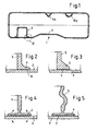
- the surge tank 2 is connected to the inner wall 3 of the fuel tank 1 such that it defines a separate volume from the filling volume of the fuel tank 1, wherein the inner wall 3 of the container directly serves as a boundary wall of the volume.
- the surge tank 2 according to the embodiment described here is formed without bottom.
- the bottom is formed by the inner wall 3 of the fuel tank 1, wherein the surge tank 2 is provided on its inner wall 3 facing side with a mounting flange 4, which is circumferentially sealed tightly welded to the inner wall 3 of the fuel tank 1.
- the surge tank 2 during the formation of the fuel tank 1 has been materially connected to the inner wall 3 of the same.
- the inner wall 3 forms a boundary wall of the surge tank 2.
- the boundary wall 5 of the surge tank 2 in the region of the mounting flange 4 an L- or T-shaped profile with a facing the inner wall 3 joining surface 6.
- the joining surface 6 of the mounting flange 4 is formed in the suitably round in cross-section formed surge tank 2 fully encircling, so that it can be sealingly welded to the inner wall 3 of the fuel tank 1 edge.
- the joining surface 6 is provided with welding ribs or weld extensions 7, the heat capacity is such that they melt in contact with the still hot and plastic inner wall 3 of the fuel tank 1 during its formation and so an intimate cohesive connection of the inner wall 3 on the one hand and joint surface. 6 on the other hand.
- the boundary wall 5, as shown in the FIGS. 4 to 8 is shown, flexibly formed, such that the mounting flange 4 is flexible or movable within certain limits and, for example, the in FIG. 8 on the right side of the figure shown angled (not rectangular) position with respect to the boundary wall 5 of the surge tank 2 can take.
- the flexibility of the mounting flange 4 with respect to the boundary wall 5 can be achieved in various ways, for example by providing a circumferential film hinge.
- the surge tank may have been made of various plastics, for example, over the height of the boundary wall 5 different hard plastics may be provided (for example, hard-soft-hard).
- profile sections 9 can be provided as built-in parts in the context of the invention, profile sections 9, the same with the inner wall 3 of the fuel tank 1 during the formation thereof so welded that they either closed channels for air and / or fuel or for receiving in cross-section Form lines.
- the profile sections 9a, b engage and hold sections only in these recorded lines.
- profile section 9a is formed in cross-section V-shaped
- FIG. 1 9b designated profile section is formed in cross-section U-shaped.
- Other geometries are readily conceivable within the scope of the invention.
- the profile sections 9a, b make use of the concept underlying the invention to use the inner wall 3 of the container as a boundary wall of a volume to be separated from the container. In this way, clamping or locking fasteners for cables can be saved.
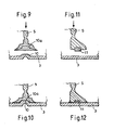
- the inner wall 3 of the fuel tank may be provided with inwardly projecting ribs 10 or the like, which cooperate with corresponding grooves 10a of the surge tank 2 and facilitate its immovable attachment to the inner wall 3 of the fuel tank 1.
- ribs 10 on the inner wall 3 of the fuel tank 1 there may also be provided grooves which cooperate with corresponding ribs of the surge tank 2.
- FIGS. 11 and 12 a variant of the surge tank is shown, which consists of a plastic which is not compatible with the inner wall 3 of the fuel tank 1 in the sense of weldable.
- a hot melt adhesive 11 or another suitable Adhesive provided, which produces a material connection in contact with the hot inner wall 3 of the fuel tank 1.
Landscapes
- Engineering & Computer Science (AREA)
- Mechanical Engineering (AREA)
- Manufacturing & Machinery (AREA)
- Life Sciences & Earth Sciences (AREA)
- Sustainable Development (AREA)
- Sustainable Energy (AREA)
- Chemical & Material Sciences (AREA)
- Combustion & Propulsion (AREA)
- Transportation (AREA)
- Cooling, Air Intake And Gas Exhaust, And Fuel Tank Arrangements In Propulsion Units (AREA)
Description
- Die Erfindung betrifft einen Kraftstoffbehälter aus thermoplastischem Kunststoff mit Funktionseinbauten zur Be- und Entlüftung, zur Kraftstpffentnahme oder dergleichen.
- Die Erfindung betrifft insbesondere einen extrusionsblasgeformten Kraftstoffbehälter aus thermoplastischem Kunststoff. Solche Behälter werden üblicherweise einstückig aus einem oder mehreren schlauchförmigen Vorformlingen gefertigt, die mittels Gasdruck an die Wandung eines mehrteiligen Formwerkzeuges angelegt werden bzw. in diesem aufgeweitet werden. Je nach dem, wie die Ausformung des Behälters im Werkzeug bewerktstelligt wird, werden Einbauteile in den Behälter entweder nach dessen Fertigstellung durch eine oder mehrere Montageöffnungen eingebracht und fixiert oder die Funktionsbauteile werden bereits während der Ausformung des Behälters in diesen eingebracht. Wird der Behälter aus einem Schlauch blasgeformt, so ist der Durchmesser des Vorformlings in der Regel so bemessen, dass dieser über einen Einbauteilehalter mit darauf angeordneten Einbauteilen extrudiert werden kann.
- Die Verschweißung von Einbauteilen mit der Innenwandung des Behälters in der ersten Hitze bei der Ausformung des Behälters hat sich insbesondere bei größeren Einbauteilen wie Schwallbehältern oder dergleichen als unvorteilhaft erwiesen, da die Auskühlung der Behälterwandung nach Fertigstellung des Artikels in den Bereichen, in denen auf der Innenwandung des Behälters Schweißflächen vorgesehen sind, behindert wird. Wird beispielsweise in dem Kraftstoffbehälter ein Schwallbehälter mit seiner Bodenaufstandsfläche großflächig mit der Innenwandung des Behälters verschweißt, so ist die Auskühlung der Behälterwandung beim Erkalten des Artikels großflächig behindert. Insbesondere die Innenkühlung des fertigen Artikels durch Gas/LuftSpülung wird beeinträchtigt. Durch die bereichsweise größere Materialakkumulation an der Behälterinnenwandung stellt sich ggf. ein Schrumpfungsverzug des Materials ein, der außen am Behälter sichtbar ist.
- Grundsätzlich wäre es jedoch aus Gründen der verfahrenstechnischen Vereinfachung wünschenswert, elnstückige aus thermoplastischem Kunststoff hergestellte Behälter bereitzustellen, die mit Einbauten bzw. Einbauteilen bestückt sind, welche bei der Herstellung in der ersten Hitze mit der Behälterwandung verbunden wurden.
- Aus der
DE 103 28 206 ist eine Vorrichtung zum Fördern von Kraftstoff aus einem Vorratsbehälter zu einer Brennkraftmaschine bekannt, bei welcher eine in einem Schwallbehälter anordnete Saugstrahlpumpe einen zweiteiligen Mischkanal aufweist, von welchem ein Teil durch die dem Vorratsbehälter zugewandte Unterseite des Topfbodens ausgebildet wird. - Aus der
DE 199 09 041 A1 ist eine Anordnung von mehreren Behältern zum Speichern von Flüssigkeit nach den Oberbegriff von Anspruch 1 vorgesehen, wobei die Behälter jeweils eine Wandung mit aus Kunststoff im Spritzgussvertahren gefertigten und miteinander verschweißen Schalenteilen und jeweils einen Anschluss zum Nachfüllen der Flüssigkeiten aufweisen. Jeweils eines der Schalenteile ist zur Begrenzung mehrerer Behälter ausgestaltet. Durch diese Gestaltung lassen sich zwei Behälter mit einem gemeinsamen Schalenteil versehen und damit als bauliche Einheit gestalten. Dadurch können beispielsweise Kraftstoff und Wasser In gemeinsamen baulichen Einheiten von zwei Behältern gespeichert werden. - Der Erfindung liegt die Aufgabe zugrunde, ein Verfahren zur Herstellung eines Kraftstoffbehälters sowie einen Kraftstoffbehälter bereitzustellen, bei dem die Funktionseinbauteile während der Ausformung des Behälters mit diesem so verbunden wurden, dass die Verbindung außen am Behälter möglichst wenig sichtbar ist.
- Die Aufgabe wird gelöst durch die Merkmale der nebengeordneten Ansprüche 1 und 2. Vorteilhafte Ausgestaltungen der Erfindung ergeben sich aus den Unteransprüchen.
- Die Erfindung kann dahingehend zusammengefasst werden, dass in den Kraftstoffbehälter solche Funktionsbauteile eingebracht werden, die erst in Zusammenwirkung mit der Innenwandung des Behälters die volle Funktionalität erhalten, sodass die Innenwandung des Behälters einen Teil der Funktionalität des betreffenden Bautells übernimmt und auch als Begrenzungswand des Funktionsbauteils wirkt. Als Funktionseinbauten können beispielsweise Profilabschnitte vorgesehen sein, die mit der Innenwandung des Behälters so verschweisst sind, dass sie mit der Innenwandung des Behälters zumindest abschnittsweise geschlossene Kanäle oder Volumlna bilden.
- Beispielsweise können die Profilabschnitte im Querschnitt halbkreisförmig, U-förmig oder V-förmig ausgebildet sein.
- Bei der Erfindung ist wenigstens ein Schwallbehälter für eine Kraftstoffpumpe vorgesehen, der auf seiner in Einbaulage der Innenwandung des Behälters zugekehrten Seite offen ist und dessen Begrenzungswand umlaufend stoffschlüssig mit der Innenwandung des Behälters verbunden ist. Auf diese Art und Weise wird eine Materialansammlung an der Behälterinnenwand vermieden, welche dadurch entsteht, dass der Boden des Schwallbehälters vollflächig auf der Innenwandung des Kraftstoffbehälters aufliegt. Bei der erfindungsgemäßen Variante bildet der Kraftstoffbehälter selbst den Boden des Schwallbehälters. Auf diese Art und Weise kann in vorteilhafter Weise ein Schwallbehälter Anwendung finden, der auf seiner der Innenwandung des Behälters abgekehrten Seite zumindest teilweise geschlossen ausgebildet ist. Ein solcher Schwallbehälter kann beispielsweise als einstückig durch Spritzgießen hergestelltes Kunststoffbauteil ausgebildet sein. Die Möglichkeit, den Schwallbehälter einstückig oder einteilig ausbilden zu können, ergibt sich insbesondere dadurch, dass der Schwallbehälter bei der Montage bzw. Verbindung mit der Innenwandung des Kraftstoffbehälters durch die Wandung des Kraftstoffbehälters verschlossen wird.
- Dass die der Innenwandung des Behälters abgekehrte Seite des Schwallbehälters geschlossen ausgebildet sein soll, ist selbstverständlich so zu verstehen, dass der Schwallbehälter Anschlüsse, Nippel oder Durchbrüche für in diesen hereinzuführende bzw. aus diesem herauszuführende Leitungen aufweisen kann.
- Zweckmäßigerweise ist die Begrenzungswand des Schwallbehälters an der in Einbaulage der Innenwandung des Behälters zugekehrten Seite mit einem umlaufenden Befestigungsflansch versehen.
- Um eine möglichst gute umlaufende stoffschlüssige Verbindung zwischen Befestigungsflansch einerseits und Innenwandung des Behälters andererseits zu erzielen, kann die Fügefläche des Befestigungsflansches profiliert ausgebildet sein. Alternativ kann die Fügefläche des Befestigungsflansches mit Schmelzvorsprüngen und/oder mit Schmelzansätzen versehen sein. Hierunter sind dünne Materialvorsprünge oder Materialansätze, Rippen oder Stege zu verstehen, die eine verhältnismäßig geringe Wärmekapazität haben und bei Berührung der betreffenden Teile der Fügefläche mit der noch heißen Innenwandung des Behälters aufgrund ihrer geringen Wärmekapazität aufschmelzen und so zur Bildung einer zuverlässigen Schweißverbindung beitragen.
- Die Begrenzungswandung des Schwallbehälters kann zumindest bereichsweise und bezogen auf den Umfang des Schwallbehälters zumindest abschnittsweise flexibel ausgebildet sein. Beispielsweise kann die Begrenzungswandung des Schwallbehälters ein umlaufendes Filmscharnier oder dergleichen aufweisen, sodass der Winkel zwischen dem Befestigungsflansch und der Behälterwandung variabel ist. So können in vorteilhafter Art und Weise Unebenheiten der Innenwandung des Behälters ausgeglichen werden. Bekanntermaßen besitzen gerade extrusionsblasgeformte Bauteile geringfügige Wandstärkentoleranzen, die bei der Auslegung von mit der Behälterwandung zu verschweißenden Einbauteilen zu berücksichtigen sind, zumindest bei solchen Einbauteilen, die umlaufend dicht mit der Behälterinnenwandung verschweißt sein müssen, wie das beispielsweise bei einem Schwallbehälter der Fall sein muss.
- Wenn als Einbauteil Profilabschnitte zur Ausbildung von Kanälen oder Aufnahmen für Leitungen vorgesehen sein sollen, besteht die Möglichkeit, diese Einbauteile insgesamt von ihrer Wandstärke so auszulegen, dass Wandstärkentoleranzen der Behälterinnenwandung beim Fügen der Einbauteile ausgeglichen werden können.
- Die Erfindung ist nachstehend anhand eines in den Zeichnung dargestellten Ausführungsbeispiels erläutert.
- Es zeigen:
- Figur 1
- einen Schnitt durch einen Kraftstoffbehälter gemäß der Erfindung,
- Figur 2
- eine vergrößerte Schnittansicht des Details II in
Figur 1 , - Figur 3
- eine alternative Ausgestaltung des in
Figur 2 dargestellten Befestigungsflansches des in dem Kraftstoffbehälter fixierten Schwallbehälters, - Figur 4
- eine weitere Ausgestaltung des Schwallbehälters im Bereich seiner Befestigung mit der Innenwandung des Behälters,
- Figur 5
- eine vierte Variante des Schwallbehälters im Bereich seiner Befestigung mit der Innenwandung des Kraftstoffbehälters,
- Figur 6
- ein fünftes Ausführungsbeispiel gemäß der Erfindung,
- Figur 7
- ein sechstes Ausführungsbeispiel gemäß der Erfindung,
- Figur 8
- einen Teilschnitt durch den Schwallbehälter des Kraftstoffbehälters gemäß der Erfindung, bei dem übertrieben eine nicht ebene Aufstands- und Befestigungsfläche auf der Innenwandung des Behälters dargestellt ist,
- Figuren 9 und 10
- ein siebtes Ausführungsbeispiel gemäß der Erfindung und
- Figuren 11 und 12
- ein nicht erfindungsgemäßes Ausführungsbeispiel
- In
Figur 1 ist eine vereinfachte Schnittansicht eines Kraftstoffbehälters 1 gemäß der Erfindung dargestellt. Der Kraftstoffbehälter 1 ist als extrusionsblasgeformter Kunststoff-Hohlkörper ausgebildet. Dieser wurde durch Extrusionsblasen eines insgesamt sechsschichtigen Coextrudats aus thermoplastischem Material mit wenigstens einer Barriereschicht für Kohlenwasserstoffe hergestellt. Dabei wurden zwei bahnförmige Vorformlinge aus thermoplastischem Material zwischen die geöffneten Teile eines insgesamt dreiteiligen Blasformwerkzeugs extrudiert. Das Blasformwerkzeug zur Herstellung eines solchen Kraftstoffbehälters 1 umfasst wenigstens zwei Außenformen und eine Mittelform, wobei jede der Außenformen eine Teilkavität bildet, die jeweils eine Hälfte des zu fertigenden Hohlkörpers definiert. In einem ersten Verfahrensschritt werden die jeweils bahnförmigen Vorformlinge zwischen einer Außenform und der Mittelform extrudiert oder angeordnet. Dabei schließen sich die Außenformen gegen die Mittelform. Auf diese Art und Weise wird ein geschlossenes Formnest gebildet, wobei mittels Gasdruckbeaufschlagung der Mittelform und/oder Evakuierung der Außenformen die Vorformlinge jeweils in die Teilkavität an der jeweiligen Außenform eingezogen werden. In der Mittelform sind vorzugsweise auf einem verfahrbaren Rahmen Bauteilträger mit auf diesen angeordneten Bauteilen vorgesehen. Über beispielsweise hydraulisch oder pneumatisch betätigbare Zylinder sind die Bauteilträger in der Mittelform verfahrbar angeordnet. Mittels dieser werden innerhalb des Behälters Funktionsbauteile platziert, derart, dass diese beispielsweise in entsprechende Aufnahmen an der Innenwandung des Behälters eingesetzt werden. - Es ist möglich auf diese Art und Weise Funktionsbauteile aus Kunststoff während der Ausformung des Behälters mit der noch plastischen Innenwandung des Behälters zu verschweißen.
- Selbstverständlich kann ein Kraftstoffbehälter, wie er nachstehend noch im Detail beschrieben wird, auch durch Tiefziehen oder Thermoformen erhalten werden, wobei ebenfalls bei einem solchen Verfahren eine Verschweißung von Funktionsbauteilen mit der Innenwandung des Behälters erfolgen kann.
- Der in
Figur 1 dargestellte Behälter ist als Kraftstoffbehälter 1 ausgebildet. Das hier beschriebene Prinzip ist jedoch ohne Weiteres auf andere geschlossene Behälter aus Kunststoff mit in diesen vorzusehenden Funktionsbauteilen übertragbar. - Der Kraftstoffbehälter 1 ist stark vereinfacht dargestellt. Dieser umfasst die üblichen Be- und Entlüftungsleitungen sowie wenigstens einen Einfüllstutzen und Leitungen zur Kraftstoffentnahme zu einer Brennkraftmaschine eines Kfz. Üblicherweise wird der Kraftstoff über mehrere Saugstrahlpumpen aus verschiedenen Teilvolumina des hier aus Vereinfachungsgründen nur mit einem einzigen Volumen dargestellten Kraftstoffbehälters 1 in einen im Kraftstoffbehälter 1 angeordneten Schwallbehälter 2 gefördert. Innerhalb des Schwallbehälters 2, der auch als Schlingertopf bezeichnet wird, ist in bekannter Art und Weise wenigstens eine elektrische Kraftstoffförderpumpe angeordnet, die aus dem Volumen des Schwallbehälters zum Motor der Brennkraftmaschine fördert, Ebenfalls aus Vereinfachungsgründen ist die Kraftstoffpumpe hier nicht dargestellt. Der Schwallbehälter 2 dient dazu, sicherzustellen, dass die Kraftstoffpumpe während aller Fahrzustände des Kfz, d. h. bei Beschleunigung, Verzögerung und Kurvenfahrt, mit Kraftstoff versorgt ist.
- Erfindungsgemäß ist vorgesehen, dass beispielsweise der Schwallbehälter 2 mit der Innenwandung 3 des Kraftstoffbehälters 1 derart verbunden ist, dass dieser ein von dem Füllvolumen des Kraftstoffbehälters 1 getrenntes Volumen definiert, wobei die Innenwandung 3 des Behälters unmittelbar als Begrenzungswand des Volumens dient. Mit anderen Worten, der Schwallbehälter 2 gemäß dem hier beschriebenen Ausführungsbeispiel ist ohne Boden ausgebildet. Der Boden wird durch die Innenwandung 3 des Kraftstoffbehälters 1 gebildet, wobei der Schwallbehälter 2 auf seiner der Innenwandung 3 zugekehrten Seite mit einem Befestigungsflansch 4 versehen ist, der umlaufend dicht mit der Innenwandung 3 des Kraftstoffbehälters 1 verschweißt ist. Hierdurch ist es möglich, den Schwallbehälter 2 als einstückiges, spritzgegossenes Bauteil auszubilden, an das alle wesentlichen Elemente angeformt sind. Bei einem auf herkömmliche Art und Weise ausgebildeten Schwallbehälter 2 mit einem Boden ist es erforderlich, diesen ggf. mit einem Deckelverschluss zu versehen, der dann mit dem Schwallbehälter 2 verrastet wird. Dies ist erforderlich, um die Kraftstoffpumpe und ggf. einen Füllstandsgeber oder dergleichen in dem Schwallbehälter 2 vorzumontieren, bevor dieser in den Kraftstoffbehälter 1 verbracht wird.
- Erfindungsgemäß ist vorgesehen, dass der Schwallbehälter 2 während der Ausformung des Kraftstoffbehälters 1 stoffschlüssig mit der Innenwandung 3 desselben verbunden wurde. Und zwar derart, wie eingangs bereits erwähnt, dass die Innenwandung 3 eine Begrenzungswand des Schwallbehälters 2 bildet.
- Wie den
Figuren 2 bis 7 zu entnehmen ist, kann die Begrenzungswand 5 des Schwallbehälters 2 im Bereich des Befestigungsflansches 4 ein L- oder T-förmiges Profil mit einer der Innenwandung 3 zugekehrten Fügefläche 6 aufweisen. Die Fügefläche 6 des Befestigungsflansches 4 ist bei dem zweckmäßigerweise im Querschnitt rund ausgebildeten Schwallbehälter 2 voll umlaufend ausgebildet, sodass dieser randseitig dichtend mit der Innenwandung 3 des Kraftstoffbehälters 1 verschweißt werden kann. - Hierzu ist die Fügefläche 6 mit Schweißrippen oder Schweißfortsätzen 7 versehen, deren Wärmekapazität so bemessen ist, dass diese bei Berührung mit der noch heißen und plastischen Innenwandung 3 des Kraftstoffbehälters 1 während dessen Ausformung aufschmelzen und so eine innige stoffschlüssige Verbindung von Innenwandung 3 einerseits und Fügefläche 6 andererseits herstellen.
- Um Wanddickentoleranzen der Behälterwandung oder gar Unebenheiten der Innenwandung ausgleichen zu können, ist die Begrenzungswand 5, wie dies in den
Figuren 4 bis 8 dargestellt ist, flexibel ausgebildet, derart, dass der Befestigungsflansch 4 in gewissen Grenzen flexibel bzw. bewegbar ist und beispielsweise die inFigur 8 auf der rechten Seite der Abbildung gezeigte abgewinkelte (nicht rechtwinklige) Position bzgl. der Begrenzungswand 5 des Schwallbehälters 2 einnehmen kann. Die Flexibilität des Befestigungsflansches 4 in Bezug auf die Begrenzungswand 5 kann auf verschiedene Art und Weise erzielt werden, beispielsweise dadurch, dass ein umlaufendes Filmscharnier vorgesehen wird. Alternativ kann der Schwallbehälter aus verschiedenen Kunststoffen hergestellt worden sein, wobei beispielsweise über die Höhe der Begrenzungswand 5 verschieden harte Kunststoffe vorgesehen sein können (beispielsweise hart-weich-hart). Auf diese Art und Weise ist ein Höhenausgleich etwaiger Vorsprünge in der Innenwandung 3 des Kraftstoffbehälters 1 möglich. Je nach Breite und Ausgestaltung des Befestigungsflansches 4 können in diesem zur Vermeidung von unzulässigen Spannungen bedingt durch die Kreisringform der Fügefläche 6 Entlastungsschlitze 8 vorgesehen sein. - Die Erfindung wurde vorstehend anhand eines Schwallbehälters 2 erläutert.
- Wie dies ebenfalls in
Figur 1 dargestellt ist, können als Einbauteile im Sinne der Erfindung auch Profilabschnitte 9 vorgesehen sein, die mit der Innenwandung 3 des Kraftstoffbehälters 1 während der Ausformung desselben so verschweißt wurden, dass diese entweder geschlossene Kanäle für Luft und/oder Kraftstoff oder zur Aufnahme von im Querschnitt runden Leitungen bilden. Im letzteren Fall können die Profilabschnitte 9a, b nur abschnittsweise in diesen aufgenommene Leitungen umgreifen und halten. - Der in
Figur 1 dargestellte Profilabschnitt 9a ist im Querschnitt V-förmig ausgebildet, der inFigur 1 als 9b bezeichnete Profilabschnitt ist im Querschnitt U-förmig ausgebildet. Andere Geometrien sind ohne Weiteres im Rahmen der Erfindung denkbar. Die Profilabschnitte 9a, b machen von dem der Erfindung zugrundeliegenden Gedanken Gebrauch, die Innenwandung 3 des Behälters als Begrenzungswand eines von dem Behälters zu trennenden Volumens zu nutzen. Auf diese Art und Weise werden Klemm- oder Rastbefestigungen für Leitungen eingespart. - Wie dies in den
Figuren 9 und 10 dargestellt ist, kann die Innenwandung 3 des Kraftstoffbehälters mit nach innen hervorstehenden Rippen 10 oder dergleichen versehen sein, die mit entsprechenden Nuten 10a des Schwallbehälters 2 zusammenwirken und dessen unverrückbare Festlegung auf der Innenwandung 3 des Kraftstoffbehälters 1 erleichtern. - Selbstverständlich können anstatt der Rippen 10 auf der Innenwandung 3 des Kraftstoffbehälters 1 auch dort Nuten vorgesehen sein, die mit entsprechenden Rippen des Schwallbehälters 2 zusammenwirken.
- In den
Figuren 11 und 12 ist eine Variante des Schwallbehälters dargestellt, der aus einem Kunststoff besteht, welcher nicht mit der Innenwandung 3 des Kraftstoffbehälters 1 kompatibel im Sinne von verschweißbar ist. In diesem Fall ist zwischen der Fügefläche 6 der Begrenzungswand 5 und der Innenwandung 3 des Kraftstoffbehälters 1 ein Heißklebstoff 11 oder ein anderer geeigneter Haftvermittler vorgesehen, der in Berührung mit der heißen Innenwandung 3 des Kraftstoffbehälters 1 eine stoffschlüssige Verbindung herstellt. -
1 Kraftstoffbehälter 2 Schwallbehälter 3 Innenwandung 4 Befestigungsflansch 5 Begrenzungswand 6 Fügefläche 7 Schweißfortsätze 8 Entlassungsschlitze 9a, b Profilabschnitte 10 Rippen 10a Nuten 11 Heißklebstoff
Claims (6)
- Kraftstoffbehälter aus thermoplastischem Kunststoff mit Funktionseinbauteilen zur Be- und Entlüftung, zur Kraftstoffentnahme oder dergleichen, wobei ein Funktionseinbauteil derart stoffschlüssig mit der Innenwandung (3) des Behälters verbunden ist, dass es mit der Behälterwandung ein von dem Füllvolumen des Behälters getrenntes Volumen definiert, derart, dass die Innenwandung (3) des Behälters unmittelbar als eine erste Begrenzungswand dieses Volumens dient, dadurch gekennzeichnet, dass das Funktionseinbauteil ein Schwallbehälter (2) mit einer eigenen Begrenzungswand (5) und mit einer in dem Schwallbehälter angeordneten elektrischen Kraftstoffförderpumpe ist, wobei der Schwallbehälter (2) auf seiner in Einbaulage der Innenwandung (3) des Behälters zugekehrten Seite ohne Boden ausgebildet ist und dessen eigenen Begrenzungswand (5) umlaufend mit der Innenwandung (3) des Behälters verschweißt ist, so dass der Boden als erste Begrenzungswand des volumens durch die Innenwandung des Behälters gebildet wird.
- Behälter nach Anspruch 1, dadurch gekennzeichnet, dass die eigene Begrenzungswand (5) des Schwallbehälters (2) an der in Einbaulage der Innenwandung (3) des Behälters zugekehrten Seite einen umlaufenden Befestigungsflansch (4) aufweist.
- Behälter nach Anspruch 2, dadurch gekennzeichnet, dass die Fügefläche (6) des Befestigungsflansches (4) profiliert ist.
- Behälter nach Anspruch 2, dadurch gekennzeichnet, dass die Fügefläche (6) des Befestigungsflansches (4) mit Schmelzvorsprüngen (7) und/oder Schmelzansätzen versehen ist.
- Behälter nach einem der Ansprüche 2 bis 4, dadurch gekennzeichnet, dass die eigene Begrenzungswandung (5) des Schwallbehälters (2) zumindest bereichsweise und bezogen auf den Umfang des Schwallbehälters (2) zumindest abschnittsweise flexibel ist.
- Behälter nach Anspruch 5 dadurch gekennzeichnet, dass der Winkel zwischen dem Befestigungsflansch (4) und der eigenen des Schwallbehälters Begrenzungswand (5) variabel ist.
Applications Claiming Priority (2)
| Application Number | Priority Date | Filing Date | Title |
|---|---|---|---|
| DE200610059799 DE102006059799A1 (de) | 2006-12-15 | 2006-12-15 | Kraftstoffbehälter aus thermoplastischem Kunststoff mit Funktionseinbauten zur Be- und Entlüftung, zur Kraftstoffentnahme oder dergleichen |
| PCT/EP2007/010068 WO2008071299A1 (de) | 2006-12-15 | 2007-11-21 | Kraftstoffbehälter aus thermoplastischem kunststoff mit funktionseinbauten zur be- und entlüftung, zur kraftstoffentnahme oder dergleichen |
Publications (2)
| Publication Number | Publication Date |
|---|---|
| EP2102026A1 EP2102026A1 (de) | 2009-09-23 |
| EP2102026B1 true EP2102026B1 (de) | 2013-06-12 |
Family
ID=39016018
Family Applications (1)
| Application Number | Title | Priority Date | Filing Date |
|---|---|---|---|
| EP20070819883 Not-in-force EP2102026B1 (de) | 2006-12-15 | 2007-11-21 | Kraftstoffbehälter aus thermoplastischem kunststoff mit funktionseinbauten zur be- und entlüftung, zur kraftstoffentnahme oder dergleichen |
Country Status (4)
| Country | Link |
|---|---|
| EP (1) | EP2102026B1 (de) |
| DE (1) | DE102006059799A1 (de) |
| ES (1) | ES2419233T3 (de) |
| WO (1) | WO2008071299A1 (de) |
Cited By (1)
| Publication number | Priority date | Publication date | Assignee | Title |
|---|---|---|---|---|
| EP4674593A1 (de) * | 2024-07-02 | 2026-01-07 | TI Automotive Technology Center GmbH | Verfahren zur herstellung eines blasformteils und blasformteil |
Families Citing this family (5)
| Publication number | Priority date | Publication date | Assignee | Title |
|---|---|---|---|---|
| CN101823425B (zh) | 2009-01-22 | 2014-05-21 | 麦格纳斯太尔燃油系统公司 | 具有内装件的燃油箱及其制造方法 |
| DE102010032278A1 (de) | 2010-07-26 | 2012-01-26 | Kautex Textron Gmbh & Co. Kg | Kraftstoffbehälter aus thermoplastischem Kunststoff |
| US8973778B2 (en) * | 2012-10-29 | 2015-03-10 | Ti Automotive Technology Center Gmbh | Self-adjusting connector |
| DE102012023035B4 (de) | 2012-11-26 | 2017-02-16 | Kautex Textron Gmbh & Co. Kg | Verfahren zur Herstellung eines Hohlkörpers aus thermoplastischem Kunststoff |
| CN104260635B (zh) * | 2014-10-11 | 2017-03-08 | 亚普汽车部件股份有限公司 | 一种三维多壁塑料中空箱体 |
Family Cites Families (7)
| Publication number | Priority date | Publication date | Assignee | Title |
|---|---|---|---|---|
| DE1704387A1 (de) * | 1967-01-04 | 1972-01-13 | Woodall Industries Inc | Hohler Kunststoffbauteil |
| DE3612194C1 (de) * | 1986-04-11 | 1986-10-16 | Daimler-Benz Ag, 7000 Stuttgart | Im Kraftstoffbehälter eines Kraftfahrzeuges vorgesehene Kraftstoffstauvorrichtung |
| DE9116117U1 (de) * | 1991-12-30 | 1993-04-29 | Westerwälder Eisenwerk Gerhard GmbH, 57586 Weitefeld | Tank mit Zwischenwand |
| DE19733949C1 (de) * | 1997-08-06 | 1999-01-21 | Mannesmann Vdo Ag | Kraftstoffversorgungssystem |
| DE19909041A1 (de) * | 1999-03-02 | 2000-09-07 | Mannesmann Vdo Ag | Zur Montage in einem Kraftfahrzeug vorgesehene Anordnung von Behältern |
| DE19948515A1 (de) * | 1999-10-08 | 2001-04-12 | Bielomatik Leuze & Co | Fügeeinheit für Haftnähte, insbesondere Vibrationsschweißungen |
| DE10328206A1 (de) * | 2003-06-24 | 2005-01-13 | Robert Bosch Gmbh | Vorrichtung zum Fördern von Kraftstoff aus einem Vorratsbehälter zu einer Brennkraftmaschine |
-
2006
- 2006-12-15 DE DE200610059799 patent/DE102006059799A1/de not_active Withdrawn
-
2007
- 2007-11-21 EP EP20070819883 patent/EP2102026B1/de not_active Not-in-force
- 2007-11-21 WO PCT/EP2007/010068 patent/WO2008071299A1/de not_active Ceased
- 2007-11-21 ES ES07819883T patent/ES2419233T3/es active Active
Cited By (1)
| Publication number | Priority date | Publication date | Assignee | Title |
|---|---|---|---|---|
| EP4674593A1 (de) * | 2024-07-02 | 2026-01-07 | TI Automotive Technology Center GmbH | Verfahren zur herstellung eines blasformteils und blasformteil |
Also Published As
| Publication number | Publication date |
|---|---|
| DE102006059799A1 (de) | 2008-06-19 |
| ES2419233T3 (es) | 2013-08-20 |
| EP2102026A1 (de) | 2009-09-23 |
| WO2008071299A1 (de) | 2008-06-19 |
Similar Documents
| Publication | Publication Date | Title |
|---|---|---|
| DE10054876C2 (de) | Doppelwandiger Kraftstoffbehälter aus Kunststoff | |
| EP2038136B1 (de) | Kraftstoffbehälter | |
| EP1058626B1 (de) | Treibstofftank mit integriertem hitzeschild | |
| DE60102887T2 (de) | Behälter mit einem Anschlussstück und Verfahren zur Herstellung desselben | |
| EP1894702B1 (de) | Verfahren zur Herstellung eines Kraftstoffbehälters | |
| DE60112408T2 (de) | Verfahren zur herstellung eines kunststoff-kraftstofftanks | |
| EP2158103B1 (de) | Kraftstoffbehälter | |
| DE10107075A1 (de) | Kraftstoffbehälter und Verfahren zu seiner Herstellung | |
| EP2148774B1 (de) | Verfahren zur herstellung eines behälters aus thermoplastischem kunststoff durch extrusionsblasformen sowie anschlusselement zur verwendung bei einem solchen verfahren | |
| DE102013004929B4 (de) | Betriebsflüssigkeitsbehälter | |
| DE102012008394A1 (de) | Extrusionsblasgeformter Kraftstoffbehälter aus thermoplastischem Kunststoff sowie Verfahren zu dessen Herstellung | |
| DE102010027096A1 (de) | Kraftstoffbehälter aus Kunststoff und Verfahren zu dessen Herstellung | |
| EP3676123A1 (de) | Flüssigkeitsbehälter für ein kraftfahrzeug und verfahren zum herstellen eines flüssigkeitsbehälters | |
| DE102012020949B4 (de) | Verfahren zur Herstellung eines Behälters aus thermoplastischem Kunststoff | |
| WO2017162412A1 (de) | Betriebsflüssigkeitsbehälter mit versteifungselement und verfahren zum herstellen eines betriebsflüssigkeitsbehälters | |
| WO2008071299A1 (de) | Kraftstoffbehälter aus thermoplastischem kunststoff mit funktionseinbauten zur be- und entlüftung, zur kraftstoffentnahme oder dergleichen | |
| EP3490776A1 (de) | Verfahren zum herstellen eines flüssigkeitsbehälters, flüssigkeitsbehälter für ein kraftfahrzeug und spritzgusswerkzeug | |
| EP3676080B1 (de) | Flüssigkeitsbehälter und verfahren zum herstellen eines flüssigkeitsbehälters | |
| EP3676069B1 (de) | Spritzgussverfahren und flüssigkeitsbehälter für ein kraftfahrzeug | |
| DE102019135439A1 (de) | Behälter mit In-Mould-Labeln und/oder mit Labeln, Verfahren und Vorrichtungen zu dessen Herstellung sowie Gebinde | |
| DE10214900A1 (de) | Kraftstoffbehälter für Kraftfahrzeuge sowie Verfahren zur Herstellung desselben | |
| EP3259110B1 (de) | Verfahren zum extrusionsblasformen eines behälters aus thermoplastischem kunststoff sowie extrusionsblasgeformter behälter | |
| WO2018095747A1 (de) | Verfahren zur herstellung eines behälters | |
| DE102014221823A1 (de) | Verfahren zur Herstellung eines Kunststoffkraftstoffbehälters | |
| EP3083193B1 (de) | Verfahren zur herstellung eines behälters aus thermoplastischem kunststoff sowie nach dem verfahren hergestellter kunststoffbehälter |
Legal Events
| Date | Code | Title | Description |
|---|---|---|---|
| PUAI | Public reference made under article 153(3) epc to a published international application that has entered the european phase |
Free format text: ORIGINAL CODE: 0009012 |
|
| 17P | Request for examination filed |
Effective date: 20090404 |
|
| AK | Designated contracting states |
Kind code of ref document: A1 Designated state(s): AT BE BG CH CY CZ DE DK EE ES FI FR GB GR HU IE IS IT LI LT LU LV MC MT NL PL PT RO SE SI SK TR |
|
| 17Q | First examination report despatched |
Effective date: 20100208 |
|
| DAX | Request for extension of the european patent (deleted) | ||
| GRAP | Despatch of communication of intention to grant a patent |
Free format text: ORIGINAL CODE: EPIDOSNIGR1 |
|
| GRAS | Grant fee paid |
Free format text: ORIGINAL CODE: EPIDOSNIGR3 |
|
| GRAA | (expected) grant |
Free format text: ORIGINAL CODE: 0009210 |
|
| AK | Designated contracting states |
Kind code of ref document: B1 Designated state(s): AT BE BG CH CY CZ DE DK EE ES FI FR GB GR HU IE IS IT LI LT LU LV MC MT NL PL PT RO SE SI SK TR |
|
| REG | Reference to a national code |
Ref country code: GB Ref legal event code: FG4D Free format text: NOT ENGLISH |
|
| REG | Reference to a national code |
Ref country code: CH Ref legal event code: EP |
|
| REG | Reference to a national code |
Ref country code: AT Ref legal event code: REF Ref document number: 616550 Country of ref document: AT Kind code of ref document: T Effective date: 20130615 |
|
| REG | Reference to a national code |
Ref country code: IE Ref legal event code: FG4D Free format text: LANGUAGE OF EP DOCUMENT: GERMAN |
|
| REG | Reference to a national code |
Ref country code: DE Ref legal event code: R096 Ref document number: 502007011897 Country of ref document: DE Effective date: 20130808 |
|
| REG | Reference to a national code |
Ref country code: ES Ref legal event code: FG2A Ref document number: 2419233 Country of ref document: ES Kind code of ref document: T3 Effective date: 20130820 |
|
| REG | Reference to a national code |
Ref country code: RO Ref legal event code: EPE |
|
| PG25 | Lapsed in a contracting state [announced via postgrant information from national office to epo] |
Ref country code: GR Free format text: LAPSE BECAUSE OF FAILURE TO SUBMIT A TRANSLATION OF THE DESCRIPTION OR TO PAY THE FEE WITHIN THE PRESCRIBED TIME-LIMIT Effective date: 20130913 Ref country code: SE Free format text: LAPSE BECAUSE OF FAILURE TO SUBMIT A TRANSLATION OF THE DESCRIPTION OR TO PAY THE FEE WITHIN THE PRESCRIBED TIME-LIMIT Effective date: 20130612 Ref country code: LT Free format text: LAPSE BECAUSE OF FAILURE TO SUBMIT A TRANSLATION OF THE DESCRIPTION OR TO PAY THE FEE WITHIN THE PRESCRIBED TIME-LIMIT Effective date: 20130612 Ref country code: SI Free format text: LAPSE BECAUSE OF FAILURE TO SUBMIT A TRANSLATION OF THE DESCRIPTION OR TO PAY THE FEE WITHIN THE PRESCRIBED TIME-LIMIT Effective date: 20130612 Ref country code: FI Free format text: LAPSE BECAUSE OF FAILURE TO SUBMIT A TRANSLATION OF THE DESCRIPTION OR TO PAY THE FEE WITHIN THE PRESCRIBED TIME-LIMIT Effective date: 20130612 |
|
| REG | Reference to a national code |
Ref country code: NL Ref legal event code: VDEP Effective date: 20130612 |
|
| REG | Reference to a national code |
Ref country code: LT Ref legal event code: MG4D |
|
| PG25 | Lapsed in a contracting state [announced via postgrant information from national office to epo] |
Ref country code: BG Free format text: LAPSE BECAUSE OF FAILURE TO SUBMIT A TRANSLATION OF THE DESCRIPTION OR TO PAY THE FEE WITHIN THE PRESCRIBED TIME-LIMIT Effective date: 20130912 |
|
| PG25 | Lapsed in a contracting state [announced via postgrant information from national office to epo] |
Ref country code: LV Free format text: LAPSE BECAUSE OF FAILURE TO SUBMIT A TRANSLATION OF THE DESCRIPTION OR TO PAY THE FEE WITHIN THE PRESCRIBED TIME-LIMIT Effective date: 20130612 |
|
| PG25 | Lapsed in a contracting state [announced via postgrant information from national office to epo] |
Ref country code: IS Free format text: LAPSE BECAUSE OF FAILURE TO SUBMIT A TRANSLATION OF THE DESCRIPTION OR TO PAY THE FEE WITHIN THE PRESCRIBED TIME-LIMIT Effective date: 20131012 Ref country code: SK Free format text: LAPSE BECAUSE OF FAILURE TO SUBMIT A TRANSLATION OF THE DESCRIPTION OR TO PAY THE FEE WITHIN THE PRESCRIBED TIME-LIMIT Effective date: 20130612 Ref country code: PT Free format text: LAPSE BECAUSE OF FAILURE TO SUBMIT A TRANSLATION OF THE DESCRIPTION OR TO PAY THE FEE WITHIN THE PRESCRIBED TIME-LIMIT Effective date: 20131014 Ref country code: EE Free format text: LAPSE BECAUSE OF FAILURE TO SUBMIT A TRANSLATION OF THE DESCRIPTION OR TO PAY THE FEE WITHIN THE PRESCRIBED TIME-LIMIT Effective date: 20130612 |
|
| PGFP | Annual fee paid to national office [announced via postgrant information from national office to epo] |
Ref country code: AT Payment date: 20131113 Year of fee payment: 7 Ref country code: CZ Payment date: 20131114 Year of fee payment: 7 |
|
| PG25 | Lapsed in a contracting state [announced via postgrant information from national office to epo] |
Ref country code: NL Free format text: LAPSE BECAUSE OF FAILURE TO SUBMIT A TRANSLATION OF THE DESCRIPTION OR TO PAY THE FEE WITHIN THE PRESCRIBED TIME-LIMIT Effective date: 20130612 Ref country code: PL Free format text: LAPSE BECAUSE OF FAILURE TO SUBMIT A TRANSLATION OF THE DESCRIPTION OR TO PAY THE FEE WITHIN THE PRESCRIBED TIME-LIMIT Effective date: 20130612 |
|
| PGFP | Annual fee paid to national office [announced via postgrant information from national office to epo] |
Ref country code: RO Payment date: 20131029 Year of fee payment: 7 Ref country code: ES Payment date: 20131128 Year of fee payment: 7 |
|
| PLBE | No opposition filed within time limit |
Free format text: ORIGINAL CODE: 0009261 |
|
| STAA | Information on the status of an ep patent application or granted ep patent |
Free format text: STATUS: NO OPPOSITION FILED WITHIN TIME LIMIT |
|
| PG25 | Lapsed in a contracting state [announced via postgrant information from national office to epo] |
Ref country code: DK Free format text: LAPSE BECAUSE OF FAILURE TO SUBMIT A TRANSLATION OF THE DESCRIPTION OR TO PAY THE FEE WITHIN THE PRESCRIBED TIME-LIMIT Effective date: 20130612 |
|
| 26N | No opposition filed |
Effective date: 20140313 |
|
| PG25 | Lapsed in a contracting state [announced via postgrant information from national office to epo] |
Ref country code: IT Free format text: LAPSE BECAUSE OF FAILURE TO SUBMIT A TRANSLATION OF THE DESCRIPTION OR TO PAY THE FEE WITHIN THE PRESCRIBED TIME-LIMIT Effective date: 20130612 |
|
| BERE | Be: lapsed |
Owner name: KAUTEX TEXTRON G.M.B.H. & CO. KG Effective date: 20131130 |
|
| REG | Reference to a national code |
Ref country code: DE Ref legal event code: R082 Ref document number: 502007011897 Country of ref document: DE Representative=s name: KIERDORF RITSCHEL PATENTANWAELTE PARTG MBB, DE Ref country code: DE Ref legal event code: R082 Ref document number: 502007011897 Country of ref document: DE Representative=s name: KIERDORF RITSCHEL RICHLY PATENTANWAELTE PARTG , DE Ref country code: DE Ref legal event code: R082 Ref document number: 502007011897 Country of ref document: DE Representative=s name: RICHLY & RITSCHEL PATENTANWAELTE PARTG MBB, DE |
|
| REG | Reference to a national code |
Ref country code: DE Ref legal event code: R097 Ref document number: 502007011897 Country of ref document: DE Effective date: 20140313 |
|
| REG | Reference to a national code |
Ref country code: CH Ref legal event code: PL |
|
| PG25 | Lapsed in a contracting state [announced via postgrant information from national office to epo] |
Ref country code: CH Free format text: LAPSE BECAUSE OF NON-PAYMENT OF DUE FEES Effective date: 20131130 Ref country code: LI Free format text: LAPSE BECAUSE OF NON-PAYMENT OF DUE FEES Effective date: 20131130 Ref country code: MC Free format text: LAPSE BECAUSE OF FAILURE TO SUBMIT A TRANSLATION OF THE DESCRIPTION OR TO PAY THE FEE WITHIN THE PRESCRIBED TIME-LIMIT Effective date: 20130612 |
|
| REG | Reference to a national code |
Ref country code: IE Ref legal event code: MM4A |
|
| PG25 | Lapsed in a contracting state [announced via postgrant information from national office to epo] |
Ref country code: BE Free format text: LAPSE BECAUSE OF NON-PAYMENT OF DUE FEES Effective date: 20131130 |
|
| PG25 | Lapsed in a contracting state [announced via postgrant information from national office to epo] |
Ref country code: IE Free format text: LAPSE BECAUSE OF NON-PAYMENT OF DUE FEES Effective date: 20131121 |
|
| PG25 | Lapsed in a contracting state [announced via postgrant information from national office to epo] |
Ref country code: CY Free format text: LAPSE BECAUSE OF FAILURE TO SUBMIT A TRANSLATION OF THE DESCRIPTION OR TO PAY THE FEE WITHIN THE PRESCRIBED TIME-LIMIT Effective date: 20130612 Ref country code: TR Free format text: LAPSE BECAUSE OF FAILURE TO SUBMIT A TRANSLATION OF THE DESCRIPTION OR TO PAY THE FEE WITHIN THE PRESCRIBED TIME-LIMIT Effective date: 20130612 |
|
| REG | Reference to a national code |
Ref country code: AT Ref legal event code: MM01 Ref document number: 616550 Country of ref document: AT Kind code of ref document: T Effective date: 20141121 |
|
| PG25 | Lapsed in a contracting state [announced via postgrant information from national office to epo] |
Ref country code: RO Free format text: LAPSE BECAUSE OF NON-PAYMENT OF DUE FEES Effective date: 20141121 Ref country code: LU Free format text: LAPSE BECAUSE OF NON-PAYMENT OF DUE FEES Effective date: 20131121 Ref country code: CZ Free format text: LAPSE BECAUSE OF NON-PAYMENT OF DUE FEES Effective date: 20141121 Ref country code: HU Free format text: LAPSE BECAUSE OF FAILURE TO SUBMIT A TRANSLATION OF THE DESCRIPTION OR TO PAY THE FEE WITHIN THE PRESCRIBED TIME-LIMIT; INVALID AB INITIO Effective date: 20071121 |
|
| PG25 | Lapsed in a contracting state [announced via postgrant information from national office to epo] |
Ref country code: MT Free format text: LAPSE BECAUSE OF FAILURE TO SUBMIT A TRANSLATION OF THE DESCRIPTION OR TO PAY THE FEE WITHIN THE PRESCRIBED TIME-LIMIT Effective date: 20130612 Ref country code: AT Free format text: LAPSE BECAUSE OF NON-PAYMENT OF DUE FEES Effective date: 20141121 |
|
| REG | Reference to a national code |
Ref country code: FR Ref legal event code: PLFP Year of fee payment: 9 |
|
| REG | Reference to a national code |
Ref country code: ES Ref legal event code: FD2A Effective date: 20160229 |
|
| PG25 | Lapsed in a contracting state [announced via postgrant information from national office to epo] |
Ref country code: ES Free format text: LAPSE BECAUSE OF NON-PAYMENT OF DUE FEES Effective date: 20141122 |
|
| REG | Reference to a national code |
Ref country code: FR Ref legal event code: PLFP Year of fee payment: 10 |
|
| REG | Reference to a national code |
Ref country code: FR Ref legal event code: PLFP Year of fee payment: 11 |
|
| PGFP | Annual fee paid to national office [announced via postgrant information from national office to epo] |
Ref country code: FR Payment date: 20171121 Year of fee payment: 11 Ref country code: DE Payment date: 20171024 Year of fee payment: 11 |
|
| PGFP | Annual fee paid to national office [announced via postgrant information from national office to epo] |
Ref country code: GB Payment date: 20171123 Year of fee payment: 11 |
|
| REG | Reference to a national code |
Ref country code: DE Ref legal event code: R119 Ref document number: 502007011897 Country of ref document: DE |
|
| GBPC | Gb: european patent ceased through non-payment of renewal fee |
Effective date: 20181121 |
|
| PG25 | Lapsed in a contracting state [announced via postgrant information from national office to epo] |
Ref country code: DE Free format text: LAPSE BECAUSE OF NON-PAYMENT OF DUE FEES Effective date: 20190601 Ref country code: FR Free format text: LAPSE BECAUSE OF NON-PAYMENT OF DUE FEES Effective date: 20181130 |
|
| PG25 | Lapsed in a contracting state [announced via postgrant information from national office to epo] |
Ref country code: GB Free format text: LAPSE BECAUSE OF NON-PAYMENT OF DUE FEES Effective date: 20181121 |