EP2103770A2 - Agencement de ferrure - Google Patents
Agencement de ferrure Download PDFInfo
- Publication number
- EP2103770A2 EP2103770A2 EP09003762A EP09003762A EP2103770A2 EP 2103770 A2 EP2103770 A2 EP 2103770A2 EP 09003762 A EP09003762 A EP 09003762A EP 09003762 A EP09003762 A EP 09003762A EP 2103770 A2 EP2103770 A2 EP 2103770A2
- Authority
- EP
- European Patent Office
- Prior art keywords
- drive rod
- wing
- fitting arrangement
- ventilation
- arrangement according
- Prior art date
- Legal status (The legal status is an assumption and is not a legal conclusion. Google has not performed a legal analysis and makes no representation as to the accuracy of the status listed.)
- Granted
Links
Images



Classifications
-
- E—FIXED CONSTRUCTIONS
- E06—DOORS, WINDOWS, SHUTTERS, OR ROLLER BLINDS IN GENERAL; LADDERS
- E06B—FIXED OR MOVABLE CLOSURES FOR OPENINGS IN BUILDINGS, VEHICLES, FENCES OR LIKE ENCLOSURES IN GENERAL, e.g. DOORS, WINDOWS, BLINDS, GATES
- E06B7/00—Special arrangements or measures in connection with doors or windows
- E06B7/02—Special arrangements or measures in connection with doors or windows for providing ventilation, e.g. through double windows; Arrangement of ventilation roses
Definitions
- the present invention relates to a fitting arrangement for a wing of a window, a door or the like with a drive rod, which from a locking position, in which the wing is in a locked state, in an open position, in which the wing is in an unlocked state , is displaceable. Furthermore, the invention is directed to a window or a door with such a fitting arrangement.
- Such fitting arrangements are used for example in rotary, Drehkipp- or sliding panels.
- rotary tilting or pure tilting wings although the possibility of ventilation in the tilted position is given, however, the risk of burglary is on the one hand increased in the tilted position and on the other it is undesirable, for example, certain weather conditions to leave the wing permanently in the tilted position.
- a continuous ventilation is usually not possible in the known wings.
- this object is achieved in that the drive rod is connected via a coupling unit with a cover, which is closed for closing and releasing an opening formed in the wing from a closed position to a release position, that the drive rod is displaceable in a ventilation position and that when moving the drive rod in the ventilation position, the cover by the Coupling unit is brought into the release position.
- a window or a door according to the invention comprise a wing and a fitting arrangement according to the invention arranged on the wing, wherein a ventilation opening is formed in the wing and the cover element for closing the ventilation opening is arranged on the outside of the wing.
- the cover is spent by the coupling unit and / or by a spring element in the closed position when moving the drive rod from the ventilation position.
- the drive rod for example, in the open position, the locking position or an optionally present tilted position, so according to the invention automatically provided in the wing opening is closed by the cover again. There are thus no additional beyond the normal condition beyond handles required, so that the operation is further simplified.
- a blocking element is provided by which a movement of the cover is blocked when the drive rod is in the locking position or in the open position.
- the blocking element thus prevents the opening in the wing from being released by the cover element when the window is locked or opened. This is essential in particular in the locking position, so that no access to the interior of the space separated by the wing from the outside world is possible via the opening formed in the wing.
- the ventilation position of the drive rod simultaneously forms a second locking position of the drive rod.
- there is a second locking position i. that the wing is locked even when the drive rod is in the ventilation position.
- the measures provided for the normal locking position locking pin also when moving the drive rod in the ventilation point in the associated Frame provided for closing pieces, whereby a locking of the wing takes place.
- the strikers as double-sided strikers, which have at their two ends latch receptacles for the locking pins and in a central region a lateral retraction of the locking pins allowed to allow a pivot opening of the wing. If, in addition, a tilted position is provided, then the closing pieces are designed accordingly in order to release the locking pins again in the tilted position.
- the coupling unit comprises a slotted guide.
- the slotted guide can be provided on the drive rod and interact with a coupled to the cover control.
- the slotted guide is connected to the cover and cooperates with a provided on the drive rod control.
- the coupling unit preferably comprises a control element which is arranged on the drive rod and can be displaced together with the latter, in particular in the form of a pin.
- the pin can be formed as a conventional locking pin, for example, as a mushroom pin.
- the slotted guide is rotatably mounted on a wing-fixed fitting part, in particular on a faceplate or on a wing flap. Due to the rotatable mounting of the guide slot associated with this cover can be switched from the closed position to the release position.
- the slotted guide comprises an obliquely extending to the drive rod control section with a sloping Ausstellkante.
- control section comprises a return edge running essentially parallel to the obliquely extending opening edge. In this way it is achieved that when pushing back the drive rod from the ventilation position, the cover is automatically transferred back into the closed position.
- the control section may preferably be arcuate in order to increase in this way the stroke of the movement of the cover between the closed position and the release position.
- control section is adjoined by a guide section extending essentially parallel to the drive rod.
- the guide portion may comprise a substantially parallel to the drive rod extending retaining edge.
- the control element connected to the drive rod preferably moves within the guide section when the drive rod is displaced between the locking position and the open position. Due to the parallel arrangement of the guide section no movement of the cover takes place in this case, so that this remains in the closed position. At the same time the cover is blocked by the retaining edge, so that it can not be opened from the outside.
- the cover is designed as an exposed ventilation flap.
- the ventilation flap can be pivoted in particular about the axis of rotation of the slotted guide.
- the cover is designed as a sliding cover, which can be moved to release the opening formed in the wing from its closed position to the release position. Even a particular parallel parking or otherwise moving the cover, through which the opening is released, is possible in principle.
- the ventilation flap is connected to the coupling unit, in particular integrally formed with the coupling unit.
- the coupling unit in particular integrally formed with the coupling unit.
- the drive rod via an actuating handle between the locking position, the open position and the ventilation position is displaceable.
- the drive rod is controlled in any other way, for example via an electric motor.
- the drive rod can be designed to be displaceable in an additional position, for example in a tilted position. If no tilted position is provided, the ventilation position can replace the tilted position, ie the ventilation position of the drive rod is reached when the actuating handle is in the position otherwise assigned to the tilted position.
- the ventilation position is present in addition to a tilted position and, for example, when the operating handle is between the open position and the tilted position or between the open position and the locking position.
- the drive rod is displaceable from the locking position via the open position into the ventilation position. This is the case, for example, when the fitting arrangement instead of tilting the wing permits a ventilation position or when the ventilation position is between the tilted position and the open position. In these two arrangements, the user-known operation remains largely intact, so that intuitive operation is possible.
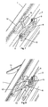
- Fig. 1 shows a wing 1 of a window, a door or the like with a face-plate 2, through which a formed in the rebate surface of the wing 1 fitting groove 3 is covered, wherein in the fitting groove 3 a displaceably mounted in the usual manner drive rod 4 is arranged.
- the peg-shaped control element 5 projects through a slot 7 formed in the face-plate rail 2 and interacts with a sliding guide 8, which is fastened to the face-plate rail 2 via a screw 9 and is mounted rotatably about the screw 9. Furthermore, the slide guide 8 is connected via a web 10 with a cover 11, wherein the web 10 through an opening 12 (see FIGS. 7 and 8 ) is guided in the rollover of the wing 1 and the cover 11 is formed to close the opening 12. When the opening 12 is closed, the cover element 11 lies flat against the outside of the rollover 1 located on the inside of the space, as shown in FIG Fig. 1 is shown.
- the drive rod 4 is coupled via the peg-shaped control element 5 and the slide guide 8 with the cover 11, so that the slide guide 8 and the peg-shaped control 5 form a coupling unit 13 of the fitting arrangement.
- the slotted guide 8 comprises an arcuate, obliquely to the drive rod 4 extending control section 14 and an adjoining parallel to the drive rod 4 extending guide portion 15.
- the control section 14 has an oblique, arcuate Ausstellkante 16 and a substantially parallel extending arcuate return edge 17th Both the Ausstellkante 16 and the return edge 17 go into a respective parallel to the drive rod 4 extending leading edge 18, 19 of the guide portion 15, wherein the leading edge 19 at the same time a retaining edge for the cover 11 and together with a holding edge 19 forming portion 20 of Slotted guide 8 forms a blocking element 21 for the cover 11.
- the peg-shaped control element 5 is arranged at the beginning of the guide portion 15 between the two leading edges 18 and 19 in this position. A folding out of the cover 11 is not possible in this state, since a required pivoting the slide guide 8 is prevented by the screw 9 by the voltage applied to the peg-shaped control element 5 retaining edge 19.
- the peg-shaped control element 5 is within the guide portion 15 into the in Fig. 1 shown shifted position. In this position, the wing 1 is locked again in a conventional manner, being ensured at the same time by the voltage applied to the peg-shaped control element 5 retaining edge 19, that the cover 11 is not lifted from the outside and thus the opening 12 can be exposed.
- FIGS. 9 and 10 show a further embodiment of an inventively designed fitting arrangement.
- Features which have already been used in the description of the first embodiment are denoted by the same reference numerals as in FIGS Fig. 1 to 8 ,
- Fig. 9 is a cover 11 'shown, at the lower end of a coupling unit 13' is formed with a slotted guide 8 '.
- the slide guide 8 ' in this case comprises a Ausstellkante 16 which cooperates with the peg-shaped control element 5 for issuing the cover 11'.
- the spring element 25 is formed as a leaf spring, which is attached at one end to the cover 11 'and is supported on the wing side of a retaining lug 26 with the other end.
- the spring bias of the cover element 11 ' can also be generated by other suitable means, for example by a spiral spring arranged around the rotation axis 24.
Landscapes
- Engineering & Computer Science (AREA)
- Civil Engineering (AREA)
- Structural Engineering (AREA)
- Specific Sealing Or Ventilating Devices For Doors And Windows (AREA)
Applications Claiming Priority (1)
| Application Number | Priority Date | Filing Date | Title |
|---|---|---|---|
| DE200820003740 DE202008003740U1 (de) | 2008-03-17 | 2008-03-17 | Beschlaganordnung |
Publications (3)
| Publication Number | Publication Date |
|---|---|
| EP2103770A2 true EP2103770A2 (fr) | 2009-09-23 |
| EP2103770A3 EP2103770A3 (fr) | 2011-10-05 |
| EP2103770B1 EP2103770B1 (fr) | 2013-05-15 |
Family
ID=40622062
Family Applications (1)
| Application Number | Title | Priority Date | Filing Date |
|---|---|---|---|
| EP20090003762 Not-in-force EP2103770B1 (fr) | 2008-03-17 | 2009-03-16 | Agencement de ferrure |
Country Status (2)
| Country | Link |
|---|---|
| EP (1) | EP2103770B1 (fr) |
| DE (1) | DE202008003740U1 (fr) |
Families Citing this family (1)
| Publication number | Priority date | Publication date | Assignee | Title |
|---|---|---|---|---|
| DE102023109444A1 (de) * | 2023-04-14 | 2024-10-17 | SCHÜCO International KG | Dreh-/Kippfenster oder Tür |
Family Cites Families (6)
| Publication number | Priority date | Publication date | Assignee | Title |
|---|---|---|---|---|
| DE19846317C2 (de) * | 1998-03-25 | 2002-10-24 | Siegenia Frank Kg | Beschlag für Fenster oder Türen |
| DE19902382C1 (de) * | 1999-01-21 | 2000-07-06 | Siegenia Frank Kg | Fenster oder Tür |
| DE10031420C2 (de) * | 2000-06-28 | 2003-04-17 | Damgartener Tischler Gmbh | Fenster mit Lüftungseinrichtung |
| DE102004043941A1 (de) * | 2004-09-11 | 2006-03-16 | Roto Frank Ag | Schubstangenanordnung |
| DE202006017044U1 (de) * | 2006-11-06 | 2007-01-04 | Siegenia-Aubi Kg | Fenster oder Tür |
| DE202007016354U1 (de) * | 2007-11-21 | 2008-02-28 | Siegenia-Aubi Kg | Fenster oder Tür mit einem Blend- und Flügelrahmen |
-
2008
- 2008-03-17 DE DE200820003740 patent/DE202008003740U1/de not_active Expired - Lifetime
-
2009
- 2009-03-16 EP EP20090003762 patent/EP2103770B1/fr not_active Not-in-force
Also Published As
| Publication number | Publication date |
|---|---|
| EP2103770B1 (fr) | 2013-05-15 |
| EP2103770A3 (fr) | 2011-10-05 |
| DE202008003740U1 (de) | 2009-08-06 |
Similar Documents
| Publication | Publication Date | Title |
|---|---|---|
| EP1286012B1 (fr) | Ferrure de verrouillage avec un elément de verrou tournante | |
| EP2692969A1 (fr) | Engrenage d'un dispositif de verrouillage à crémone, dispositif de verrouillage avec un tel engrenage ainsi que fenêtre, porte ou analogue avec un tel dispositif de verrouillage à crémone | |
| EP1582673B1 (fr) | Gâche pour fenêtre ou porte-fenêtres | |
| DE68903724T2 (de) | Beschlag fuer tuer, fenster oder dergleichen. | |
| WO2018206307A1 (fr) | Fenêtre ou porte à limitation d'ouverture en basculement anti-effraction | |
| DE19725677C2 (de) | Fenster oder Tür an Wohnwagen, Wohnmobilen oder sonstigen Fahrzeugen, mit Verriegelungseinrichtungen mit gemeinsamer Betätigungshandhabe | |
| EP0735223A1 (fr) | Ferrure pour battant pivotant et/ou basculant de fenêtres, portes ou similaires avec dispositif de levage du battant arrangé entre le battant et le cadre | |
| DE102006010755A1 (de) | Verstellvorrichtung für einen Schiebedachdeckel an einem Fahrzeug | |
| DE102012100424A1 (de) | Vorrichtung für das Steuern der Schliessfolge von zweiflügeligen Schwenktüren | |
| EP1243725A2 (fr) | Serrure à fermeture assistée | |
| DE10237492B3 (de) | Vorrichtung zum Öffnen und/oder Schließen eines Flügels relativ zu einem Rahmenstock | |
| EP2103770B1 (fr) | Agencement de ferrure | |
| EP0905343B1 (fr) | Agencement de fenêtre ou de porte | |
| DE10257688A1 (de) | Verschussvorrichtung für eine in einem Fahrzeug vorgesehene Öffnung mit einer einzigen Gleitführungsschiene sowie entsprechendes Fahrzeug | |
| EP1818489B1 (fr) | Fenêtre ou porte de sécurité inhibant l'effraction | |
| DE10013697A1 (de) | Feststellvorrichtung | |
| EP1590548B1 (fr) | Ferrure oscillobattante | |
| DE19906071C2 (de) | Drehbegrenzer für Dreh-Schiebe-Fenster | |
| EP4174266A1 (fr) | Agencement de battant | |
| EP1580362B1 (fr) | Porte coulissante, fenêtre coulissante ou similaire | |
| EP2320013B1 (fr) | Armature dotée d'une transmission de renvoi | |
| DE102024203222B3 (de) | Beschlaganordnung für ein Fenster, eine Tür oder dergleichen zur Betätigung einer Feststellbremse | |
| EP1715125A2 (fr) | Ferrures pour fenêtre oscillobattante avec une position pour créer une fente de ventilation | |
| DE29818045U1 (de) | Beschlag für Klappfenster, insbesondere von Wohnwagen, Mobilheimen u.dgl. | |
| DE102007035123A1 (de) | Kippsicherung |
Legal Events
| Date | Code | Title | Description |
|---|---|---|---|
| PUAI | Public reference made under article 153(3) epc to a published international application that has entered the european phase |
Free format text: ORIGINAL CODE: 0009012 |
|
| AK | Designated contracting states |
Kind code of ref document: A2 Designated state(s): AT BE BG CH CY CZ DE DK EE ES FI FR GB GR HR HU IE IS IT LI LT LU LV MC MK MT NL NO PL PT RO SE SI SK TR |
|
| AX | Request for extension of the european patent |
Extension state: AL BA RS |
|
| RAP1 | Party data changed (applicant data changed or rights of an application transferred) |
Owner name: MACO VERMOEGENSVERWALTUNG GMBH |
|
| PUAL | Search report despatched |
Free format text: ORIGINAL CODE: 0009013 |
|
| AK | Designated contracting states |
Kind code of ref document: A3 Designated state(s): AT BE BG CH CY CZ DE DK EE ES FI FR GB GR HR HU IE IS IT LI LT LU LV MC MK MT NL NO PL PT RO SE SI SK TR |
|
| AX | Request for extension of the european patent |
Extension state: AL BA RS |
|
| RIC1 | Information provided on ipc code assigned before grant |
Ipc: E05C 9/00 20060101ALI20110826BHEP Ipc: E06B 7/10 20060101ALI20110826BHEP Ipc: E06B 7/02 20060101AFI20110826BHEP |
|
| 17P | Request for examination filed |
Effective date: 20111026 |
|
| RAP1 | Party data changed (applicant data changed or rights of an application transferred) |
Owner name: MACO TECHNOLOGIE GMBH |
|
| AKX | Designation fees paid |
Designated state(s): AT BE BG CH CY CZ DE DK EE ES FI FR GB GR HR HU IE IS IT LI LT LU LV MC MK MT NL NO PL PT RO SE SI SK TR |
|
| RIC1 | Information provided on ipc code assigned before grant |
Ipc: E05C 9/00 20060101ALI20120803BHEP Ipc: E06B 7/02 20060101AFI20120803BHEP Ipc: E06B 7/10 20060101ALI20120803BHEP |
|
| GRAP | Despatch of communication of intention to grant a patent |
Free format text: ORIGINAL CODE: EPIDOSNIGR1 |
|
| GRAS | Grant fee paid |
Free format text: ORIGINAL CODE: EPIDOSNIGR3 |
|
| GRAA | (expected) grant |
Free format text: ORIGINAL CODE: 0009210 |
|
| AK | Designated contracting states |
Kind code of ref document: B1 Designated state(s): AT BE BG CH CY CZ DE DK EE ES FI FR GB GR HR HU IE IS IT LI LT LU LV MC MK MT NL NO PL PT RO SE SI SK TR |
|
| REG | Reference to a national code |
Ref country code: GB Ref legal event code: FG4D Free format text: NOT ENGLISH Ref country code: CH Ref legal event code: EP |
|
| REG | Reference to a national code |
Ref country code: AT Ref legal event code: REF Ref document number: 612248 Country of ref document: AT Kind code of ref document: T Effective date: 20130615 |
|
| REG | Reference to a national code |
Ref country code: IE Ref legal event code: FG4D Free format text: LANGUAGE OF EP DOCUMENT: GERMAN |
|
| REG | Reference to a national code |
Ref country code: DE Ref legal event code: R096 Ref document number: 502009007069 Country of ref document: DE Effective date: 20130711 |
|
| REG | Reference to a national code |
Ref country code: SK Ref legal event code: T3 Ref document number: E 14196 Country of ref document: SK |
|
| REG | Reference to a national code |
Ref country code: NL Ref legal event code: T3 |
|
| REG | Reference to a national code |
Ref country code: LT Ref legal event code: MG4D |
|
| PG25 | Lapsed in a contracting state [announced via postgrant information from national office to epo] |
Ref country code: ES Free format text: LAPSE BECAUSE OF FAILURE TO SUBMIT A TRANSLATION OF THE DESCRIPTION OR TO PAY THE FEE WITHIN THE PRESCRIBED TIME-LIMIT Effective date: 20130826 Ref country code: SE Free format text: LAPSE BECAUSE OF FAILURE TO SUBMIT A TRANSLATION OF THE DESCRIPTION OR TO PAY THE FEE WITHIN THE PRESCRIBED TIME-LIMIT Effective date: 20130515 Ref country code: IS Free format text: LAPSE BECAUSE OF FAILURE TO SUBMIT A TRANSLATION OF THE DESCRIPTION OR TO PAY THE FEE WITHIN THE PRESCRIBED TIME-LIMIT Effective date: 20130915 Ref country code: GR Free format text: LAPSE BECAUSE OF FAILURE TO SUBMIT A TRANSLATION OF THE DESCRIPTION OR TO PAY THE FEE WITHIN THE PRESCRIBED TIME-LIMIT Effective date: 20130816 Ref country code: PT Free format text: LAPSE BECAUSE OF FAILURE TO SUBMIT A TRANSLATION OF THE DESCRIPTION OR TO PAY THE FEE WITHIN THE PRESCRIBED TIME-LIMIT Effective date: 20130916 Ref country code: NO Free format text: LAPSE BECAUSE OF FAILURE TO SUBMIT A TRANSLATION OF THE DESCRIPTION OR TO PAY THE FEE WITHIN THE PRESCRIBED TIME-LIMIT Effective date: 20130815 Ref country code: SI Free format text: LAPSE BECAUSE OF FAILURE TO SUBMIT A TRANSLATION OF THE DESCRIPTION OR TO PAY THE FEE WITHIN THE PRESCRIBED TIME-LIMIT Effective date: 20130515 Ref country code: FI Free format text: LAPSE BECAUSE OF FAILURE TO SUBMIT A TRANSLATION OF THE DESCRIPTION OR TO PAY THE FEE WITHIN THE PRESCRIBED TIME-LIMIT Effective date: 20130515 Ref country code: LT Free format text: LAPSE BECAUSE OF FAILURE TO SUBMIT A TRANSLATION OF THE DESCRIPTION OR TO PAY THE FEE WITHIN THE PRESCRIBED TIME-LIMIT Effective date: 20130515 |
|
| PG25 | Lapsed in a contracting state [announced via postgrant information from national office to epo] |
Ref country code: BG Free format text: LAPSE BECAUSE OF FAILURE TO SUBMIT A TRANSLATION OF THE DESCRIPTION OR TO PAY THE FEE WITHIN THE PRESCRIBED TIME-LIMIT Effective date: 20130815 Ref country code: PL Free format text: LAPSE BECAUSE OF FAILURE TO SUBMIT A TRANSLATION OF THE DESCRIPTION OR TO PAY THE FEE WITHIN THE PRESCRIBED TIME-LIMIT Effective date: 20130515 Ref country code: HR Free format text: LAPSE BECAUSE OF FAILURE TO SUBMIT A TRANSLATION OF THE DESCRIPTION OR TO PAY THE FEE WITHIN THE PRESCRIBED TIME-LIMIT Effective date: 20130515 |
|
| PG25 | Lapsed in a contracting state [announced via postgrant information from national office to epo] |
Ref country code: LV Free format text: LAPSE BECAUSE OF FAILURE TO SUBMIT A TRANSLATION OF THE DESCRIPTION OR TO PAY THE FEE WITHIN THE PRESCRIBED TIME-LIMIT Effective date: 20130515 |
|
| PG25 | Lapsed in a contracting state [announced via postgrant information from national office to epo] |
Ref country code: DK Free format text: LAPSE BECAUSE OF FAILURE TO SUBMIT A TRANSLATION OF THE DESCRIPTION OR TO PAY THE FEE WITHIN THE PRESCRIBED TIME-LIMIT Effective date: 20130515 Ref country code: EE Free format text: LAPSE BECAUSE OF FAILURE TO SUBMIT A TRANSLATION OF THE DESCRIPTION OR TO PAY THE FEE WITHIN THE PRESCRIBED TIME-LIMIT Effective date: 20130515 Ref country code: CZ Free format text: LAPSE BECAUSE OF FAILURE TO SUBMIT A TRANSLATION OF THE DESCRIPTION OR TO PAY THE FEE WITHIN THE PRESCRIBED TIME-LIMIT Effective date: 20130515 |
|
| PG25 | Lapsed in a contracting state [announced via postgrant information from national office to epo] |
Ref country code: RO Free format text: LAPSE BECAUSE OF FAILURE TO SUBMIT A TRANSLATION OF THE DESCRIPTION OR TO PAY THE FEE WITHIN THE PRESCRIBED TIME-LIMIT Effective date: 20130515 |
|
| PLBE | No opposition filed within time limit |
Free format text: ORIGINAL CODE: 0009261 |
|
| STAA | Information on the status of an ep patent application or granted ep patent |
Free format text: STATUS: NO OPPOSITION FILED WITHIN TIME LIMIT |
|
| 26N | No opposition filed |
Effective date: 20140218 |
|
| PGFP | Annual fee paid to national office [announced via postgrant information from national office to epo] |
Ref country code: NL Payment date: 20140319 Year of fee payment: 6 Ref country code: SK Payment date: 20140313 Year of fee payment: 6 |
|
| REG | Reference to a national code |
Ref country code: DE Ref legal event code: R097 Ref document number: 502009007069 Country of ref document: DE Effective date: 20140218 |
|
| PGFP | Annual fee paid to national office [announced via postgrant information from national office to epo] |
Ref country code: AT Payment date: 20140312 Year of fee payment: 6 Ref country code: IT Payment date: 20140321 Year of fee payment: 6 Ref country code: FR Payment date: 20140319 Year of fee payment: 6 |
|
| PGFP | Annual fee paid to national office [announced via postgrant information from national office to epo] |
Ref country code: GB Payment date: 20140319 Year of fee payment: 6 |
|
| PGFP | Annual fee paid to national office [announced via postgrant information from national office to epo] |
Ref country code: DE Payment date: 20140530 Year of fee payment: 6 |
|
| PG25 | Lapsed in a contracting state [announced via postgrant information from national office to epo] |
Ref country code: LU Free format text: LAPSE BECAUSE OF FAILURE TO SUBMIT A TRANSLATION OF THE DESCRIPTION OR TO PAY THE FEE WITHIN THE PRESCRIBED TIME-LIMIT Effective date: 20140316 |
|
| REG | Reference to a national code |
Ref country code: CH Ref legal event code: PL |
|
| REG | Reference to a national code |
Ref country code: IE Ref legal event code: MM4A |
|
| PG25 | Lapsed in a contracting state [announced via postgrant information from national office to epo] |
Ref country code: IE Free format text: LAPSE BECAUSE OF NON-PAYMENT OF DUE FEES Effective date: 20140316 Ref country code: LI Free format text: LAPSE BECAUSE OF NON-PAYMENT OF DUE FEES Effective date: 20140331 Ref country code: CH Free format text: LAPSE BECAUSE OF NON-PAYMENT OF DUE FEES Effective date: 20140331 |
|
| REG | Reference to a national code |
Ref country code: DE Ref legal event code: R119 Ref document number: 502009007069 Country of ref document: DE |
|
| REG | Reference to a national code |
Ref country code: AT Ref legal event code: MM01 Ref document number: 612248 Country of ref document: AT Kind code of ref document: T Effective date: 20150316 |
|
| GBPC | Gb: european patent ceased through non-payment of renewal fee |
Effective date: 20150316 |
|
| REG | Reference to a national code |
Ref country code: NL Ref legal event code: MM Effective date: 20150401 |
|
| REG | Reference to a national code |
Ref country code: SK Ref legal event code: MM4A Ref document number: E 14196 Country of ref document: SK Effective date: 20150316 |
|
| PG25 | Lapsed in a contracting state [announced via postgrant information from national office to epo] |
Ref country code: IT Free format text: LAPSE BECAUSE OF NON-PAYMENT OF DUE FEES Effective date: 20150316 |
|
| REG | Reference to a national code |
Ref country code: FR Ref legal event code: ST Effective date: 20151130 |
|
| PG25 | Lapsed in a contracting state [announced via postgrant information from national office to epo] |
Ref country code: DE Free format text: LAPSE BECAUSE OF NON-PAYMENT OF DUE FEES Effective date: 20151001 Ref country code: GB Free format text: LAPSE BECAUSE OF NON-PAYMENT OF DUE FEES Effective date: 20150316 |
|
| PG25 | Lapsed in a contracting state [announced via postgrant information from national office to epo] |
Ref country code: FR Free format text: LAPSE BECAUSE OF NON-PAYMENT OF DUE FEES Effective date: 20150331 Ref country code: SK Free format text: LAPSE BECAUSE OF NON-PAYMENT OF DUE FEES Effective date: 20150316 Ref country code: MT Free format text: LAPSE BECAUSE OF FAILURE TO SUBMIT A TRANSLATION OF THE DESCRIPTION OR TO PAY THE FEE WITHIN THE PRESCRIBED TIME-LIMIT Effective date: 20130515 Ref country code: AT Free format text: LAPSE BECAUSE OF NON-PAYMENT OF DUE FEES Effective date: 20150316 |
|
| PG25 | Lapsed in a contracting state [announced via postgrant information from national office to epo] |
Ref country code: MC Free format text: LAPSE BECAUSE OF FAILURE TO SUBMIT A TRANSLATION OF THE DESCRIPTION OR TO PAY THE FEE WITHIN THE PRESCRIBED TIME-LIMIT Effective date: 20130515 |
|
| PG25 | Lapsed in a contracting state [announced via postgrant information from national office to epo] |
Ref country code: CY Free format text: LAPSE BECAUSE OF FAILURE TO SUBMIT A TRANSLATION OF THE DESCRIPTION OR TO PAY THE FEE WITHIN THE PRESCRIBED TIME-LIMIT Effective date: 20130515 |
|
| PG25 | Lapsed in a contracting state [announced via postgrant information from national office to epo] |
Ref country code: HU Free format text: LAPSE BECAUSE OF FAILURE TO SUBMIT A TRANSLATION OF THE DESCRIPTION OR TO PAY THE FEE WITHIN THE PRESCRIBED TIME-LIMIT; INVALID AB INITIO Effective date: 20090316 Ref country code: TR Free format text: LAPSE BECAUSE OF FAILURE TO SUBMIT A TRANSLATION OF THE DESCRIPTION OR TO PAY THE FEE WITHIN THE PRESCRIBED TIME-LIMIT Effective date: 20130515 |
|
| PG25 | Lapsed in a contracting state [announced via postgrant information from national office to epo] |
Ref country code: NL Free format text: LAPSE BECAUSE OF NON-PAYMENT OF DUE FEES Effective date: 20150401 |
|
| PG25 | Lapsed in a contracting state [announced via postgrant information from national office to epo] |
Ref country code: BE Free format text: LAPSE BECAUSE OF NON-PAYMENT OF DUE FEES Effective date: 20140331 |
|
| PG25 | Lapsed in a contracting state [announced via postgrant information from national office to epo] |
Ref country code: MK Free format text: LAPSE BECAUSE OF FAILURE TO SUBMIT A TRANSLATION OF THE DESCRIPTION OR TO PAY THE FEE WITHIN THE PRESCRIBED TIME-LIMIT Effective date: 20130515 |