EP2105367B1 - Verfahren zur Steuerung eines zusätzlichen Brems- oder Antriebsorgans einer Seilbahnanlage - Google Patents
Verfahren zur Steuerung eines zusätzlichen Brems- oder Antriebsorgans einer Seilbahnanlage Download PDFInfo
- Publication number
- EP2105367B1 EP2105367B1 EP09290131A EP09290131A EP2105367B1 EP 2105367 B1 EP2105367 B1 EP 2105367B1 EP 09290131 A EP09290131 A EP 09290131A EP 09290131 A EP09290131 A EP 09290131A EP 2105367 B1 EP2105367 B1 EP 2105367B1
- Authority
- EP
- European Patent Office
- Prior art keywords
- installation
- during
- motor means
- speed
- braking
- Prior art date
- Legal status (The legal status is an assumption and is not a legal conclusion. Google has not performed a legal analysis and makes no representation as to the accuracy of the status listed.)
- Active
Links
Images

Classifications
-
- B—PERFORMING OPERATIONS; TRANSPORTING
- B66—HOISTING; LIFTING; HAULING
- B66D—CAPSTANS; WINCHES; TACKLES, e.g. PULLEY BLOCKS; HOISTS
- B66D5/00—Braking or detent devices characterised by application to lifting or hoisting gear, e.g. for controlling the lowering of loads
- B66D5/02—Crane, lift hoist, or winch brakes operating on drums, barrels, or ropes
-
- B—PERFORMING OPERATIONS; TRANSPORTING
- B61—RAILWAYS
- B61B—RAILWAY SYSTEMS; EQUIPMENT THEREFOR NOT OTHERWISE PROVIDED FOR
- B61B12/00—Component parts, details or accessories not provided for in groups B61B7/00 - B61B11/00
- B61B12/06—Safety devices or measures against cable fracture
-
- B—PERFORMING OPERATIONS; TRANSPORTING
- B61—RAILWAYS
- B61B—RAILWAY SYSTEMS; EQUIPMENT THEREFOR NOT OTHERWISE PROVIDED FOR
- B61B12/00—Component parts, details or accessories not provided for in groups B61B7/00 - B61B11/00
- B61B12/10—Cable traction drives
-
- G—PHYSICS
- G01—MEASURING; TESTING
- G01L—MEASURING FORCE, STRESS, TORQUE, WORK, MECHANICAL POWER, MECHANICAL EFFICIENCY, OR FLUID PRESSURE
- G01L5/00—Apparatus for, or methods of, measuring force, work, mechanical power, or torque, specially adapted for specific purposes
-
- G—PHYSICS
- G01—MEASURING; TESTING
- G01M—TESTING STATIC OR DYNAMIC BALANCE OF MACHINES OR STRUCTURES; TESTING OF STRUCTURES OR APPARATUS, NOT OTHERWISE PROVIDED FOR
- G01M99/00—Subject matter not provided for in other groups of this subclass
Definitions
- the invention relates to a method of controlling at least one braking or auxiliary moving element of a cable transport installation according to the characteristics of the preamble of the independent claim 1.
- control will be synonymous with diagnosis or verification of the state of a system.
- the invention also relates to software directly loadable in the memory of a controller for controlling the steps of the method when said software is executed.
- the braking means and / or auxiliary moving members of a cable transport installation must be checked periodically. In order to carry out these tests in conditions as close as possible to the conditions of use, the braking is generally tested when the installation is loaded.
- a braking or auxiliary moving member for a cable transport installation driving vehicles said cable extending in a closed loop between at least two pulleys of which at least one is driven by driving means comprising a main motor, said member being intended to transmit a torque to the driving pulley, characterized in that it comprises the following successive steps: a) from a stabilized regime of the installation, determines a curve representative of the speed variation of the vehicles when the member is in a normal active state, the vehicles being in charge and the main engine not being powered; b) the value of the instantaneous torque to be transmitted to the driving pulley is determined so as to reproduce, at the level of the driving pulley, the effects of the inertia and / or the resistant torque due, during step a), to the loads installed in the vehicles; ; c) from the same stabilized regime of the installation as for step a), the organ is actuated to its active state to carry out its control when the vehicles
- This method makes it possible to remedy these drawbacks by arranging the actual loads on the installation only during a first step, and by simulating the effects of the loads by the application of an instantaneous torque delivered by the motor means during the test of the loads. braking or auxiliary moving parts.
- step c) which is carried out periodically to verify the operation of the member, the effects of the inertia and / or the load torque due to the loads are simulated.
- this method requires to unclamp the variator of the main motor so that the main motor can produce the necessary torque in step b) mentioned above.
- the torque produced by the main motor exceeds the normal limits of use, which can lead to damage to the motor and / or the drive.
- this control method does not provide for totally controlling certain braking members, and in particular the braking members controlled by a modulation of the force as a function of the deceleration of the line. Indeed, in the method of the prior art, the modulation must in particular be suspended before testing the organ, since the modulation would correct a slight malfunction of the braking member which would then go unnoticed.
- the instantaneous value of the second curve is greater, at each moment, than the value of the first setpoint curve.
- control methods of the state of the art do not make it possible to test such braking units.
- the methods of the prior art do not effectively check the release of the second braking member when the braking force provided by the first member is not sufficient.
- the invention aims to remedy these problems by proposing a method of controlling a braking member or auxiliary movement allowing complete periodic tests to be carried out, without using loads and sparing the mechanical installation.
- the invention further aims to provide a method for controlling the operation of a braking unit of the type mentioned above.
- the method according to the invention provides the mechanical installation because the torque delivered by the motor means is a known and limited torque.
- the method makes it possible to test various types of braking members and this, whatever their modes of application: with or without modulation, organ by organ, several organs simultaneously, etc.
- the method also makes it possible to test a braking unit comprising two brakes respectively controlled by a first modulated signal for controlling the speed of the cable according to a first deceleration setpoint curve; and by a second modulated signal for controlling the speed of the cable according to a second deceleration curve, the instantaneous value of the second curve being greater, at each instant, than the value of the first setpoint curve.
- a well-chosen constant torque makes it possible to check the tripping of each of the brakes, in particular the release of the second brake, and the joint operation of the two brakes.
- V test curve is compared to a reference curve established when the organ is in a set state. It is then possible to appreciate the setting of the organ under test.
- the constant torque C delivered by the motor means produces a driving or resistant effect greater than the effects of the inertia and / or the resisting torque due to the actual loads.
- test phase of the auxiliary moving member comprises at least two sequences in which the main motor means respectively deliver a constant torque C 1 and a constant torque C 2 .
- This step makes it possible to check the correct operation of the variator and to make sure that its characteristics have not been drifted over time.
- the method comprises a test phase during which the motor means deliver a constant constant torque C and a test phase. during which the motor means deliver a constant driving torque C.
- a braking member controlled by a modulation of the force is controlled as a function of the deceleration of the line; the method comprising a first test phase in which the modulation is suspended and a second test phase in which the braking member is controlled by a modulation of the effort.
- the method makes it possible to have additional data making it possible to facilitate the diagnosis of the organ under test and in particular to determine that the brake applies the braking force, and that the coefficient of friction between the brake and the pulley is within standard conditions.
- the pressure P ref is compared with a reference pressure established when the member is in a set state.
- the position of the vehicles driven by the cable is synchronized when the activation of the organ is triggered.
- the position of the driven vehicles is synchronized by means of a passing audible warning device, which makes it possible to launch the test phase for the same position of the vehicles.
- the invention relates to software directly loadable in the memory of a PLC for controlling the steps of the method according to the first aspect of the invention, when said software is executed.
- the method according to the invention not only verifies the overall functioning of the organ but also makes it possible to verify the acceptability, element by element, of the organ. Thus, if one observes a difference from the reference data, one can determine the element of the problem organ and act directly on it to adjust the organ. A new test after adjustment validates the correction action performed with the defective element.
- a cable transport facility is generally composed of at least two stations between which at least one mobile transport cable forms a loop in order to transport one or more vehicles from one station to another.
- vehicle means any means of transport by cable such as chairlifts, gondolas, cable cars, funiculars, etc.
- the vehicle or vehicles may be suspended from the moving cable which ensures their training.
- the vehicles can be suspended from fixed cables via a roller balancer, and driven along the fixed cables by the movable transport cable.
- the cable In order to transport the vehicles, the cable is driven by a driving pulley cooperating with motor means by means of a disengageable device for transmitting the movement.
- the motor means are, for example, composed of one or more main electric motors.
- the installation also includes an emergency engine taking over the main engines in the event of failure of the latter.
- the installation is equipped with one or more service brakes and one or more emergency brakes.
- the service brake (s) act on the output shaft of the main engine or on the transmission shaft of the motion transmission device.
- the emergency brakes to overcome a failure of the cable drive means, generally act directly on the sides of the drive pulley.
- the emergency and service brakes are intended to directly or indirectly transmit a torque to the driving pulley.
- the opening of the brakes is actuated by hydraulic or pneumatic means such as cylinders, while mechanical return means such as springs, allow to return the braking means to their closed braking position.
- the hydraulic or pneumatic means are, for some service brakes and / or emergency, controlled by a braking force modulation device according to the deceleration of the line.
- the installation is provided with pressure sensors for measuring the pressure in the braking members and means for recording the information from the sensor.
- the installation is equipped with a control unit for the braking members making it possible to selectively inhibit the braking members by electrical or mechanical means and / or to inhibit the modulation of the braking elements.
- a control unit for the braking members making it possible to selectively inhibit the braking members by electrical or mechanical means and / or to inhibit the modulation of the braking elements.
- one or more braking members are provided.
- the installation may be equipped with a braking unit, of the type described in the document EP 1 884 432 , comprising two brakes respectively controlled by a first control signal for controlling the speed of the cable according to a first deceleration curve and by a second control signal for controlling the speed of the cable according to a second deceleration curve, which is greater, at each moment, to the value of the first curve.
- a braking unit of the type described in the document EP 1 884 432 , comprising two brakes respectively controlled by a first control signal for controlling the speed of the cable according to a first deceleration curve and by a second control signal for controlling the speed of the cable according to a second deceleration curve, which is greater, at each moment, to the value of the first curve.
- a variable speed drive powers the main electric motor so that it can vary its speed from standstill to its nominal speed.
- This stop is for example, performed by gradually lowering the armature voltage on a drive C.C., or by injection of a direct current on a frequency converter.
- the method according to the invention aims at controlling a braking member, such as the service or emergency brakes, the electromagnetic brakes, a unit of braking as defined above and / or an auxiliary moving member of a cable transport installation, such as the emergency engine.
- a braking member such as the service or emergency brakes, the electromagnetic brakes, a unit of braking as defined above and / or an auxiliary moving member of a cable transport installation, such as the emergency engine.
- the control method according to the invention comprises a first prior phase of acquisition of reference data or phase of development of a reference system. This phase is carried out when the installation is mechanically lapped. In addition, before proceeding with the data acquisition, the braking and / or auxiliary movement components are adjusted in accordance with the standards and regulations in force.
- the steady state corresponds to a regime in which the speed of the vehicles is constant.
- the stabilized speed corresponds to the stop mode of the installation, that is to say the speed at which the speed of the vehicles is zero.
- the motor means is supplied with a drive controlled by a control signal to vary the speed of the motor until it stops.
- the prior phase of acquisition of the reference data comprises a step of determining the constant torque C to be delivered by the motor means to produce a driving or resistant effect greater than the effects of the inertia and / or the resisting torque due to the actual charges.
- the constant torque C "resistant loads" to be delivered by the drive means is determined when the member is activated on the vacuum plant from a steady state to obtain a downtime.
- Ta ' which is lower than Ta' resistant charges'.
- the determination of the torque C will, for example, be carried out by means of in situ empirical tests.
- the constant torque C "driving loads” or “load resistant” delivered by the motor means produces a driving or resistant effect greater than the effects of the inertia and / or the resisting torque due to actual loads.
- Tests are carried out independently with driving loads and with heavy loads for each brake regardless of the type of brake installed (service brake (s) and emergency brake (s)). In addition, tests are carried out both when the modulation of the effort is suspended and when the brake is controlled by a force modulation device according to the deceleration of the line.
- Similar types of tests are also performed when activating the auxiliary backup engine. To do this, from the steady state, corresponding to the stopping regime of the installation, activates the auxiliary backup motor on the installation provided with real loads, the main motor means being stopped. During these tests, the actual loads are emptied as the vehicles advance. The speed of the installation is measured at a time t 1 , for example in load, and the speed of the installation at a time t 2 , for example when the installation is empty.
- a constant torque C 1 delivered by the main motor means is determined to obtain the speed of the installation measured previously at time t 1 , when the setting device is activated.
- auxiliary movement on the vacuum system from a steady state and a constant torque C 2 delivered by the main motor means to obtain the speed of the installation at time t 2 , when activating the organ auxiliary movement on the vacuum system.
- the application of a torque C "driving loads” makes it possible artificially to lengthen the braking in order to tend towards a time between the time obtained during the load tests and a maximum regulation (the tested brake absorbs the maximum energy).
- the application of a torque C "driving loads” makes it possible to force the deceleration below the modulation threshold of the brake.
- the modulation applies the totality of the available effort.
- the deceleration is forced below the modulation threshold of the first braking brake member and the second modulation of the second braking member then intervenes to apply the missing force.
- the method according to the invention makes it possible to verify that the second braking member is actuated when the braking force supplied by the first member is not sufficient and also makes it possible to check the joint action of the two braking members.
- it will also record the evolution of the pressure in the braking members, to verify the joint action of the two braking members.
- a series of reference speed curve records are also made for the control of the auxiliary motor.
- the vacuum system is driven by the motor means delivering, initially, the torque C 1 determined previously and, in a second step, the torque C 2.
- the auxiliary motor is simultaneously activated and a speed curve V ref is recorded.
- the sliding pressure is also measured for each brake by simulating a driving torque.
- the shutdown system of the installation it causes the vacuum installation by the main motor means delivering a constant torque C, the pressure is varied in the braking member; and measuring the pressure P ref in the braking member when the installation exceeds a threshold speed V "threshold".
- control method according to the invention comprises at least one test phase of the braking members or auxiliary movement which is carried out periodically to control the functioning of the organs.
- a speed curve V test is recorded. This curve is recorded when, from a steady state of the vacuum system, the installation is carried out by the motor means delivering the constant torque C determined previously and the member is activated simultaneously.
- the speed curve V test is then compared with the reference curve or curves V ref corresponding to a setting of the default organ, set or in excess. If no difference is observed between the curves V test and V ref, it can then be deduced that the organ is correctly adjusted. On the contrary, if the curve V test obtained exceeds the limits set by the curves V ref "default” and V ref "in excess", it follows that the organ must be adjusted again.
- test phase of the auxiliary motion-setting member comprises two sequences, the motor means delivering, during the first sequence, the determined torque C 1 and, in the second sequence, the torque C 2 .
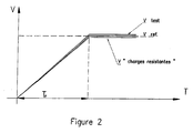
- the figures 1 and 2 illustrate, for example, the curves recorded during the tests of the installation under load: V "resistant loads” and V “driving loads", during the development of the reference system V ref and during the test phase of the organ V test.
- the figure 1 represents curves for the control of a braking member while the figure 2 represents curves for controlling an auxiliary moving member such as the safety motor.
- This software makes it possible, in particular, to manage the recording and display of the speed curves, the control of the motor means for delivering the constant torque C, the control of the braking members or the auxiliary movement members, the management of the speed curves. the synchronization of the tests, the recording and display of the pressure curves of the braking devices, etc.
- the software allows storage of information acquired during control operations.
Landscapes
- Engineering & Computer Science (AREA)
- Mechanical Engineering (AREA)
- Transportation (AREA)
- Physics & Mathematics (AREA)
- General Physics & Mathematics (AREA)
- Testing Of Devices, Machine Parts, Or Other Structures Thereof (AREA)
- Control Of Electric Motors In General (AREA)
Claims (15)
- Verfahren zur Steuerung von mindestens einem zusätzlichen Brems- oder Antriebsorgans einer Seilbahnanlage, die mindestens ein Fahrzeug antreibt, wobei das Seil durch eine Rolle angetrieben wird, die mit den Hauptmotoren zusammenarbeitet, dadurch gekennzeichnet, dass das Steuerungsverfahren mindestens einen Prüfschritt des besagten Organs enthält, während dessen ausgehend von einem stabilisierten Betriebszustand der Anlage:- die Anlage im Leerlauf durch die Hauptmotoren betrieben wird, die ein konstantes Drehmoment C liefern;- das Brems- oder Antriebsorgan gleichzeitig aktiviert wird; und- eine Geschwindigkeitskurve V test aufgezeichnet wird.
- Verfahren zur Steuerung nach Anspruch 1, dadurch gekennzeichnet, dass es einen vorangehenden Schritt zur Erfassung von Referenzdaten umfasst, im Laufe dessen :- das Organ eingestellt wird;- ausgehend von einem stabilisierten Betriebszustand die Anlage im Leerlauf durch die Motoren betrieben wird, die das konstante Drehmoment C liefern;- das Brems- oder Antriebsorgan gleichzeitig aktiviert wird;- mindestens eine Geschwindigkeitskurve V ref aufgezeichnet wird;wobei der Prüfschritt einen Schritt zum Vergleich der Geschwindigkeitskurven V test und V ref umfasst.
- Verfahren zur Steuerung nach Anspruch 2, dadurch gekennzeichnet, dass der vorangehende Schritt zur Erfassung von Referenzdaten einen Schritt zur Bestimmung des Drehmoments C umfasst, während dessen:- ausgehend von einem stabilisierten Betriebszustand ein Bremsorgan an der Anlage aktiviert wird, welche mit tatsächlichen Antriebs- oder Widerstandslasten versehen ist, wobei die Motoren abgestellt sind;- die Haltezeit Ta der Anlage gemessen wird;- das konstante Drehmoment C, das von den Hauptmotoren geliefert wird, bestimmt wird, um eine Haltezeit Ta' zu erhalten, die, wenn das Organ in der Anlage im Leerlauf ausgehend von einem stabilisierten Betriebszustand aktiviert wird, größer als Ta ist, wenn die tatsächlichen Lasten Antriebslasten sind und kleiner als Ta ist, wenn die Lasten Widerstandslasten sind.
- Verfahren zur Steuerung nach Anspruch 2 oder 3, dadurch gekennzeichnet, dass der vorangehende Schritt zur Erfassung von Referenzdaten einen Schritt zur Bestimmung des Drehmoments C umfasst, während dessen:- ausgehend von einem stabilisierten Betriebszustand das zusätzliche Antriebsorgan in der Anlage aktiviert wird, welche mit tatsächlichen Antriebs- oder Widerstandslasten versehen ist, wobei die Hauptmotoren abgestellt sind und die Linie nach und nach beim Ankommen der Fahrzeuge geleert wird;- die Geschwindigkeit der Anlage an einem Zeitpunkt t1 und die Geschwindigkeit der Anlage an einem Zeitpunkt t2 gemessen werden;- das von den Hauptmotoren gelieferte konstante Drehmoment C1, bestimmt wird, um die Geschwindigkeit der Anlage an einem Zeitpunkt t1 zu erhalten, wenn das zusätzliche Antriebsorgan an der Installation im Leerlauf ausgehend von einem stabilisierten Betriebszustand aktiviert wird;- das von den Hauptmotoren gelieferte konstante Drehmoment C2, bestimmt wird, um, um die Geschwindigkeit der Anlage an einem Zeitpunkt t2 zu erhalten, wenn das zusätzliche Antriebsorgan an der Installation im Leerlauf ausgehend von einem stabilisierten Betriebszustand aktiviert wird.
- Verfahren zur Steuerung nach Anspruch 4, dadurch gekennzeichnet, dass der Prüfschritt des zusätzlichen Antriebsorgans mindestens zwei Sequenzen umfasst, während derer die Hauptmotoren jeweils ein konstantes Drehmoment C1 und dann ein konstantes Drehmoment C2 liefern.
- Verfahren zur Steuerung nach einem beliebigen der Ansprüche 2 bis 5, dadurch gekennzeichnet, dass es einen Schritt zur Überprüfung der Entwicklung der inhärenten Kennwerte der Anlage umfasst, welche umfassen:- während des vorangehenden Schritts zur Erfassung von Referenzdaten ein Schritt des Aufzeichnens einer Geschwindigkeitskurve "Trägheit im Leerlauf" Vo, während derer ausgehend von einem stabilisierten Betriebszustand, die Rollen der Motoren der im Leerlauf betriebenen Anlage ausgekuppelt werden; und- während des Prüfschritts ein Schritt des Aufzeichnens einer Geschwindigkeitskurve "Trägheit im Leerlauf" V1, während derer ausgehend von einem stabilisierten Betriebszustand, die Rollen der Motoren der im Leerlauf betriebenen Anlage ausgekuppelt werden; und einen Arbeitsschritt zum Vergleich der Kurven "Trägheit im Leerlauf" Vo und "Trägheit im Leerlauf" V1.
- Verfahren zur Steuerung nach einem beliebigen der Ansprüche 2 bis 6, dadurch gekennzeichnet, dass es einen Prüfschritt der Kenndaten der Motoren umfasst, welche umfassen :- während des vorangehenden Schritts zur Erfassung von Referenzdaten ein Schritt des Aufzeichnens einer Geschwindigkeitskurve "elektrischer Stopp" Vo, während derer ausgehend von einem stabilisierten Betriebszustand der Anlage im Leerlauf, die Motoren von einem stufenlosen Getriebe gespeist werden, das von einem Steuersignal gesteuert wird, mit dem Ziel, die Geschwindigkeit des Motors bis zum Stillstand zu variieren; und- während des Prüfschritts ein Schritt des Aufzeichnens einer - Geschwindigkeitskurve "elektrischer Stopp" V1, während derer ausgehend von einem stabilisierten Betriebszustand der Anlage im Leerlauf, die Motoren von einem stufenlosen Getriebe gespeist werden, das von einem Steuersignal gesteuert wird, mit dem Ziel, die Geschwindigkeit des Motors bis zum Stillstand zu variieren; und einen Arbeitsschritt zum Vergleich der Kurven "elektrischer Stopp" Vo und "elektrischer Stopp" V1.
- Verfahren zur Steuerung nach einem beliebigen der Ansprüche 2 bis 7, dadurch gekennzeichnet, dass während des vorangehenden Schritts zur Erfassung von Referenzdaten mehrere Geschwindigkeitskurven V ref aufgezeichnet werden, die der Einstellung des Organs als Standard, bei Überschuss oder nach geltenden Normen entsprechenen.
- Verfahren zur Steuerung nach einem beliebigen der Ansprüche 1 bis 8, dadurch gekennzeichnet, dass es einen Prüfschritt umfasst, während dessen die Motoren ein Widerstandsmoment C liefern und einen Prüfschritt, während dessen die Motoren ein Antriebsmoment C liefern.
- Verfahren zur Steuerung nach einem beliebigen der Ansprüche 1 bis 9, dadurch gekennzeichnet, dass ein Bremsorgan durch die Modulation der Kräfte in Abhängigkeit von der Bremsung der Linie gesteuert wird; wobei das Verfahren einen ersten Prüfschritt umfasst, während dessen die Modulation ausgesetzt ist und einen zweiten Prüfschritt, während dessen das Bremsorgan durch eine Modulation der Kräfte gesteuert wird.
- Verfahren zur Steuerung nach einem beliebigen der Ansprüche 1 bis 10, dadurch gekennzeichnet, dass es ferner einen Schritt der Überwachung des Gleitdrucks eines Bremsorgans umfasst, welcher Folgendes umfasst:- ausgehend vom Stillstandszustand der Anlage wird die Anlage im Leerlauf durch die Hauptmotoren betrieben, die ein konstantes Drehmoment C liefern;- der Druck im Bremsorgan variiert wird; und- der Prüfdruck P im Bremsorgan gemessen wird, wenn die Anlage eine Grenzgeschwindigkeit V "Grenze" überschreitet.
- Verfahren zur Steuerung nach Anspruch 11, dadurch gekennzeichnet, dass während des vorangehenden Schritts zur Erfassung von Referenzdaten:- ausgehend vom Stillstandszustand der Anlage die Anlage im Leerlauf von den Hauptmotoren betrieben wird, die ein konstantes Drehmoment C liefern;- der Druck im Bremsorgan variiert wird; und- der Prüfdruck P ref im Bremsorgan gemessen wird, wenn die Anlage eine Grenzgeschwindigkeit V "Grenze" überschreitet;- der Prüfschritt einen Vergleichsschritt der Drücke P ref und P test umfasst.
- Verfahren zur Steuerung nach einem beliebigen der Ansprüche 2 bis 12, dadurch gekennzeichnet, dass während der Schritte der Prüfung und zur Erfassung von Referenzdaten, die Lage der durch das Seil angetriebenen Fahrzeuge synchronisiert wird, wenn die Aktivierung des Organs ausgelöst wird.
- Verfahren zur Steuerung nach einem beliebigen der Ansprüche 1 bis 13, dadurch gekennzeichnet, dass die Lage der angetriebenen Fahrzeuge durch ein akustisches Warnsignal der Durchfahrt der Fahrzeuge synchronisiert wird.
- Software, die direkt in den Speicher eines Automaten geladen werden kann, um die Schritte eines beliebigen der Patenansprüche 1 bis 14 zu steuern, wenn besagtes Programm ausgeführt wird.
Applications Claiming Priority (1)
| Application Number | Priority Date | Filing Date | Title |
|---|---|---|---|
| FR0851340A FR2928124B1 (fr) | 2008-02-29 | 2008-02-29 | Procede de controle d'un organe de freinage ou de mise en mouvement auxiliaire d'une installation de transport par cable. |
Publications (3)
| Publication Number | Publication Date |
|---|---|
| EP2105367A2 EP2105367A2 (de) | 2009-09-30 |
| EP2105367A3 EP2105367A3 (de) | 2009-12-02 |
| EP2105367B1 true EP2105367B1 (de) | 2012-08-01 |
Family
ID=39885139
Family Applications (1)
| Application Number | Title | Priority Date | Filing Date |
|---|---|---|---|
| EP09290131A Active EP2105367B1 (de) | 2008-02-29 | 2009-02-24 | Verfahren zur Steuerung eines zusätzlichen Brems- oder Antriebsorgans einer Seilbahnanlage |
Country Status (7)
| Country | Link |
|---|---|
| US (1) | US20090293601A1 (de) |
| EP (1) | EP2105367B1 (de) |
| JP (1) | JP2009208765A (de) |
| KR (1) | KR20090093889A (de) |
| CN (1) | CN101520354A (de) |
| CA (1) | CA2655898A1 (de) |
| FR (1) | FR2928124B1 (de) |
Cited By (1)
| Publication number | Priority date | Publication date | Assignee | Title |
|---|---|---|---|---|
| FR3129912A1 (fr) | 2021-12-03 | 2023-06-09 | Nidec Asi S.P.A. | Procédé pour vérifier l'efficacité de freinage d'un système de transport par câble |
Families Citing this family (8)
| Publication number | Priority date | Publication date | Assignee | Title |
|---|---|---|---|---|
| US8573133B2 (en) * | 2009-09-22 | 2013-11-05 | Pomagalski | Passenger transport installation comprising independent vehicles travelling on tracks and hauled by cables, and method for transporting passengers |
| JP5660840B2 (ja) * | 2010-10-07 | 2015-01-28 | 日本ケーブル株式会社 | 索条牽引車両の制動試験装置 |
| CN102279070B (zh) * | 2011-07-13 | 2013-07-10 | 天津大学 | 缆索水阻尼测试系统变速驱动装置 |
| US8686670B2 (en) | 2011-12-20 | 2014-04-01 | Magnetek, Inc. | Method and apparatus for calibrating and testing brake holding torque |
| EP2918536B1 (de) * | 2014-03-12 | 2022-06-22 | ABB Schweiz AG | Zustandsüberwachung einer vertikalen transportausrüstung |
| CN108445245B (zh) * | 2018-06-06 | 2024-02-23 | 迈克医疗电子有限公司 | 试剂盒加载和卸载装置、样本分析仪 |
| CN114261412B (zh) * | 2022-03-01 | 2022-05-24 | 弥费实业(上海)有限公司 | 一种空中运输车转向控制方法及系统 |
| CN118618439B (zh) * | 2024-08-14 | 2024-10-11 | 湖南川孚智能科技有限公司 | 一种架空索道应急运输装置 |
Family Cites Families (14)
| Publication number | Priority date | Publication date | Assignee | Title |
|---|---|---|---|---|
| FR2122809A5 (de) * | 1971-01-22 | 1972-09-01 | Pomagalski Sa | |
| JPS6054227B2 (ja) * | 1979-05-11 | 1985-11-29 | 株式会社日立製作所 | 交流エレベ−タ−の制御装置 |
| US4939679A (en) * | 1988-08-09 | 1990-07-03 | Otis Elevator Company | Recalibrating an elevator load measuring system |
| US5077508A (en) * | 1989-01-30 | 1991-12-31 | Wycoff David C | Method and apparatus for determining load holding torque |
| JPH0543150A (ja) * | 1991-08-20 | 1993-02-23 | Hitachi Ltd | エレベータ |
| IT1257416B (it) * | 1992-08-05 | 1996-01-15 | Metodo ed apparato per il controllo e la correzione automatica del comando di decelerazione-arresto della cabina di un ascensore o di un montacarichi al variare dei dati di funzionamento dell'impianto. | |
| EP1688383A4 (de) * | 2003-11-21 | 2011-09-21 | Mitsubishi Electric Corp | Aufzugssystem |
| FI118684B (fi) * | 2004-01-09 | 2008-02-15 | Kone Corp | Menetelmä ja järjestelmä hissin jarrujen kunnon testaamiseksi |
| FR2890929B1 (fr) * | 2005-09-21 | 2007-11-09 | Telepheriques Tarentaise Mauri | Procede et dispositif de controle d'un organe de freinage ou de mise en mouvement auxiliaire pour installation de transport a cable |
| US20080067011A1 (en) * | 2006-06-19 | 2008-03-20 | Nicolas Gremaud | Method of checking elevator braking equipment, a method for placing an elevator in operation and equipment for carrying out placing in operation |
| CN101163634B (zh) * | 2006-08-03 | 2011-02-09 | 三菱电机株式会社 | 电梯装置 |
| FR2904594B1 (fr) * | 2006-08-04 | 2008-10-17 | Pomagalski Sa | Procede de commande d'une unite de freinage d'une installation de transport par cable et unite de freinage. |
| FR2909060B1 (fr) * | 2006-11-23 | 2009-02-13 | Pomagalski Sa | Procede de simulation du freinage d'une installation de transport par cable, procede de diagnostic du freinage d'une telle installation dispositif de commande de l'intallation. |
| FI120070B (fi) * | 2007-10-01 | 2009-06-15 | Kone Corp | Sähkökäytön annon rajoittaminen sekä hissin suojaus |
-
2008
- 2008-02-29 FR FR0851340A patent/FR2928124B1/fr active Active
-
2009
- 2009-02-24 EP EP09290131A patent/EP2105367B1/de active Active
- 2009-02-26 CA CA002655898A patent/CA2655898A1/fr not_active Abandoned
- 2009-02-27 US US12/394,703 patent/US20090293601A1/en not_active Abandoned
- 2009-02-27 JP JP2009045742A patent/JP2009208765A/ja not_active Withdrawn
- 2009-02-27 KR KR1020090017048A patent/KR20090093889A/ko not_active Withdrawn
- 2009-03-02 CN CN200910126037A patent/CN101520354A/zh active Pending
Cited By (1)
| Publication number | Priority date | Publication date | Assignee | Title |
|---|---|---|---|---|
| FR3129912A1 (fr) | 2021-12-03 | 2023-06-09 | Nidec Asi S.P.A. | Procédé pour vérifier l'efficacité de freinage d'un système de transport par câble |
Also Published As
| Publication number | Publication date |
|---|---|
| CN101520354A (zh) | 2009-09-02 |
| JP2009208765A (ja) | 2009-09-17 |
| FR2928124B1 (fr) | 2012-02-10 |
| EP2105367A2 (de) | 2009-09-30 |
| US20090293601A1 (en) | 2009-12-03 |
| EP2105367A3 (de) | 2009-12-02 |
| KR20090093889A (ko) | 2009-09-02 |
| CA2655898A1 (fr) | 2009-08-29 |
| FR2928124A1 (fr) | 2009-09-04 |
Similar Documents
| Publication | Publication Date | Title |
|---|---|---|
| EP2105367B1 (de) | Verfahren zur Steuerung eines zusätzlichen Brems- oder Antriebsorgans einer Seilbahnanlage | |
| CA2583136C (fr) | Procede et dispositif pour realiser un controle de l'etat de sante d'un turbomoteur d'un giravion bimoteur | |
| EP1413736A1 (de) | Elektromechanische Schubumkehrvorrichtung für ein Bläsertriebwerk mit Umkehrklappen | |
| FR2791749A1 (fr) | Procede et dispositif pour determiner le point d'attaque d'un embrayage assiste | |
| EP2086810B1 (de) | Verfahren zur simulation des bremsens eines kabeltransportsystems, verfahren zur diagnose des bremsens des systems und steuervorrichtung für das system | |
| WO2016030616A1 (fr) | Dispositif et procédé de démarrage d'une turbine à gaz, procédé de régulation de la vitesse de rotation d'une turbine à gaz, et turbine à gaz et turbomoteur associés | |
| EP1036917B1 (de) | Selbsttestarchitektur für den Überdrehzahlschutz- und den Notausschaltkreislauf | |
| WO1994010434A1 (fr) | Systeme de controle moteur a corps de papillon motorise | |
| FR3049036A1 (fr) | Procede de surveillance d'au moins une roue libre d'un aeronef a voilure tournante, et aeronef | |
| FR3014616A1 (fr) | Procede de regulation d'une commande d'un actionneur electrique de wastegate par mesure du courant traversant l'actionneur electrique | |
| FR3024803A1 (fr) | Procede de surveillance des court-circuits sur les moteurs couple | |
| FR3068942B1 (fr) | Procede de demarrage d’un vehicule hybride avec une puissance de batterie augmentee | |
| CA3112149C (fr) | Systeme et procede d'aide a la synchronisation d'une roue libre et vehicule associe | |
| FR3015672A1 (fr) | Systeme et procede de test d'une machine tournante | |
| FR3136059A1 (fr) | Procédé d’adaptation automatique d’un cycle d’essai de véhicule piloté par un robot de conduite et robot de conduite | |
| EP2602601A1 (de) | Überwachungssystem einer kinematischen Kette | |
| EP2786320B1 (de) | Verfahren zur bestimmung der stabilität eines elektrischen systems | |
| FR3129912A1 (fr) | Procédé pour vérifier l'efficacité de freinage d'un système de transport par câble | |
| FR2890929A1 (fr) | Procede et dispositif de controle d'un organe de freinage ou de mise en mouvement auxiliaire pour installation de transport a cable | |
| EP3044482B1 (de) | Verfahren und system zur steuerung eines automatischen getriebes | |
| FR3024774B1 (fr) | Dispositif de test pour collecter des donnees de fonctionnement d'un moteur de vehicule et son procede de mise en oeuvre | |
| FR2918760A1 (fr) | Procede et dispositif de diagnostic d'une grandeur de sortie fournie par un moteur a courant continu | |
| FR3161799A3 (fr) | Systeme d’application de pression de batterie | |
| EP4605637A1 (de) | Verfahren und modul zur erkennung des zustands einer kupplungsvorrichtung sowie zugehöriges turbinentriebwerk und luftfahrzeug | |
| EP3303203B1 (de) | Überwachung einer aufzugseinrichtung mit geschlossenem regelkreis |
Legal Events
| Date | Code | Title | Description |
|---|---|---|---|
| PUAI | Public reference made under article 153(3) epc to a published international application that has entered the european phase |
Free format text: ORIGINAL CODE: 0009012 |
|
| AK | Designated contracting states |
Kind code of ref document: A2 Designated state(s): AT BE BG CH CY CZ DE DK EE ES FI FR GB GR HR HU IE IS IT LI LT LU LV MC MK MT NL NO PL PT RO SE SI SK TR |
|
| AX | Request for extension of the european patent |
Extension state: AL BA RS |
|
| PUAL | Search report despatched |
Free format text: ORIGINAL CODE: 0009013 |
|
| AK | Designated contracting states |
Kind code of ref document: A3 Designated state(s): AT BE BG CH CY CZ DE DK EE ES FI FR GB GR HR HU IE IS IT LI LT LU LV MC MK MT NL NO PL PT RO SE SI SK TR |
|
| AX | Request for extension of the european patent |
Extension state: AL BA RS |
|
| 17P | Request for examination filed |
Effective date: 20100525 |
|
| 17Q | First examination report despatched |
Effective date: 20100623 |
|
| AKX | Designation fees paid |
Designated state(s): AT BE BG CH CY CZ DE DK EE ES FI FR GB GR HR HU IE IS IT LI LT LU LV MC MK MT NL NO PL PT RO SE SI SK TR |
|
| GRAP | Despatch of communication of intention to grant a patent |
Free format text: ORIGINAL CODE: EPIDOSNIGR1 |
|
| GRAS | Grant fee paid |
Free format text: ORIGINAL CODE: EPIDOSNIGR3 |
|
| GRAA | (expected) grant |
Free format text: ORIGINAL CODE: 0009210 |
|
| AK | Designated contracting states |
Kind code of ref document: B1 Designated state(s): AT BE BG CH CY CZ DE DK EE ES FI FR GB GR HR HU IE IS IT LI LT LU LV MC MK MT NL NO PL PT RO SE SI SK TR |
|
| REG | Reference to a national code |
Ref country code: GB Ref legal event code: FG4D Free format text: NOT ENGLISH |
|
| REG | Reference to a national code |
Ref country code: CH Ref legal event code: EP Ref country code: AT Ref legal event code: REF Ref document number: 568493 Country of ref document: AT Kind code of ref document: T Effective date: 20120815 |
|
| REG | Reference to a national code |
Ref country code: IE Ref legal event code: FG4D Free format text: LANGUAGE OF EP DOCUMENT: FRENCH |
|
| REG | Reference to a national code |
Ref country code: DE Ref legal event code: R096 Ref document number: 602009008635 Country of ref document: DE Effective date: 20120920 |
|
| REG | Reference to a national code |
Ref country code: CH Ref legal event code: NV Representative=s name: NOVAGRAAF INTERNATIONAL SA, CH |
|
| REG | Reference to a national code |
Ref country code: NL Ref legal event code: VDEP Effective date: 20120801 |
|
| REG | Reference to a national code |
Ref country code: LT Ref legal event code: MG4D Effective date: 20120801 |
|
| PG25 | Lapsed in a contracting state [announced via postgrant information from national office to epo] |
Ref country code: NO Free format text: LAPSE BECAUSE OF FAILURE TO SUBMIT A TRANSLATION OF THE DESCRIPTION OR TO PAY THE FEE WITHIN THE PRESCRIBED TIME-LIMIT Effective date: 20121101 Ref country code: IS Free format text: LAPSE BECAUSE OF FAILURE TO SUBMIT A TRANSLATION OF THE DESCRIPTION OR TO PAY THE FEE WITHIN THE PRESCRIBED TIME-LIMIT Effective date: 20121201 Ref country code: LT Free format text: LAPSE BECAUSE OF FAILURE TO SUBMIT A TRANSLATION OF THE DESCRIPTION OR TO PAY THE FEE WITHIN THE PRESCRIBED TIME-LIMIT Effective date: 20120801 Ref country code: HR Free format text: LAPSE BECAUSE OF FAILURE TO SUBMIT A TRANSLATION OF THE DESCRIPTION OR TO PAY THE FEE WITHIN THE PRESCRIBED TIME-LIMIT Effective date: 20120801 Ref country code: FI Free format text: LAPSE BECAUSE OF FAILURE TO SUBMIT A TRANSLATION OF THE DESCRIPTION OR TO PAY THE FEE WITHIN THE PRESCRIBED TIME-LIMIT Effective date: 20120801 Ref country code: CY Free format text: LAPSE BECAUSE OF FAILURE TO SUBMIT A TRANSLATION OF THE DESCRIPTION OR TO PAY THE FEE WITHIN THE PRESCRIBED TIME-LIMIT Effective date: 20120801 |
|
| PG25 | Lapsed in a contracting state [announced via postgrant information from national office to epo] |
Ref country code: GR Free format text: LAPSE BECAUSE OF FAILURE TO SUBMIT A TRANSLATION OF THE DESCRIPTION OR TO PAY THE FEE WITHIN THE PRESCRIBED TIME-LIMIT Effective date: 20121102 Ref country code: SE Free format text: LAPSE BECAUSE OF FAILURE TO SUBMIT A TRANSLATION OF THE DESCRIPTION OR TO PAY THE FEE WITHIN THE PRESCRIBED TIME-LIMIT Effective date: 20120801 Ref country code: LV Free format text: LAPSE BECAUSE OF FAILURE TO SUBMIT A TRANSLATION OF THE DESCRIPTION OR TO PAY THE FEE WITHIN THE PRESCRIBED TIME-LIMIT Effective date: 20120801 Ref country code: PL Free format text: LAPSE BECAUSE OF FAILURE TO SUBMIT A TRANSLATION OF THE DESCRIPTION OR TO PAY THE FEE WITHIN THE PRESCRIBED TIME-LIMIT Effective date: 20120801 Ref country code: SI Free format text: LAPSE BECAUSE OF FAILURE TO SUBMIT A TRANSLATION OF THE DESCRIPTION OR TO PAY THE FEE WITHIN THE PRESCRIBED TIME-LIMIT Effective date: 20120801 Ref country code: PT Free format text: LAPSE BECAUSE OF FAILURE TO SUBMIT A TRANSLATION OF THE DESCRIPTION OR TO PAY THE FEE WITHIN THE PRESCRIBED TIME-LIMIT Effective date: 20121203 |
|
| PG25 | Lapsed in a contracting state [announced via postgrant information from national office to epo] |
Ref country code: NL Free format text: LAPSE BECAUSE OF FAILURE TO SUBMIT A TRANSLATION OF THE DESCRIPTION OR TO PAY THE FEE WITHIN THE PRESCRIBED TIME-LIMIT Effective date: 20120801 |
|
| PG25 | Lapsed in a contracting state [announced via postgrant information from national office to epo] |
Ref country code: RO Free format text: LAPSE BECAUSE OF FAILURE TO SUBMIT A TRANSLATION OF THE DESCRIPTION OR TO PAY THE FEE WITHIN THE PRESCRIBED TIME-LIMIT Effective date: 20120801 Ref country code: ES Free format text: LAPSE BECAUSE OF FAILURE TO SUBMIT A TRANSLATION OF THE DESCRIPTION OR TO PAY THE FEE WITHIN THE PRESCRIBED TIME-LIMIT Effective date: 20121112 Ref country code: EE Free format text: LAPSE BECAUSE OF FAILURE TO SUBMIT A TRANSLATION OF THE DESCRIPTION OR TO PAY THE FEE WITHIN THE PRESCRIBED TIME-LIMIT Effective date: 20120801 Ref country code: CZ Free format text: LAPSE BECAUSE OF FAILURE TO SUBMIT A TRANSLATION OF THE DESCRIPTION OR TO PAY THE FEE WITHIN THE PRESCRIBED TIME-LIMIT Effective date: 20120801 Ref country code: DK Free format text: LAPSE BECAUSE OF FAILURE TO SUBMIT A TRANSLATION OF THE DESCRIPTION OR TO PAY THE FEE WITHIN THE PRESCRIBED TIME-LIMIT Effective date: 20120801 |
|
| PG25 | Lapsed in a contracting state [announced via postgrant information from national office to epo] |
Ref country code: SK Free format text: LAPSE BECAUSE OF FAILURE TO SUBMIT A TRANSLATION OF THE DESCRIPTION OR TO PAY THE FEE WITHIN THE PRESCRIBED TIME-LIMIT Effective date: 20120801 |
|
| PLBE | No opposition filed within time limit |
Free format text: ORIGINAL CODE: 0009261 |
|
| STAA | Information on the status of an ep patent application or granted ep patent |
Free format text: STATUS: NO OPPOSITION FILED WITHIN TIME LIMIT |
|
| 26N | No opposition filed |
Effective date: 20130503 |
|
| PG25 | Lapsed in a contracting state [announced via postgrant information from national office to epo] |
Ref country code: BG Free format text: LAPSE BECAUSE OF FAILURE TO SUBMIT A TRANSLATION OF THE DESCRIPTION OR TO PAY THE FEE WITHIN THE PRESCRIBED TIME-LIMIT Effective date: 20121101 |
|
| REG | Reference to a national code |
Ref country code: DE Ref legal event code: R097 Ref document number: 602009008635 Country of ref document: DE Effective date: 20130503 |
|
| BERE | Be: lapsed |
Owner name: POMAGALSKI Effective date: 20130228 |
|
| PG25 | Lapsed in a contracting state [announced via postgrant information from national office to epo] |
Ref country code: MC Free format text: LAPSE BECAUSE OF NON-PAYMENT OF DUE FEES Effective date: 20130228 |
|
| GBPC | Gb: european patent ceased through non-payment of renewal fee |
Effective date: 20130224 |
|
| REG | Reference to a national code |
Ref country code: IE Ref legal event code: MM4A |
|
| PG25 | Lapsed in a contracting state [announced via postgrant information from national office to epo] |
Ref country code: GB Free format text: LAPSE BECAUSE OF NON-PAYMENT OF DUE FEES Effective date: 20130224 Ref country code: IE Free format text: LAPSE BECAUSE OF NON-PAYMENT OF DUE FEES Effective date: 20130224 Ref country code: BE Free format text: LAPSE BECAUSE OF NON-PAYMENT OF DUE FEES Effective date: 20130228 |
|
| PG25 | Lapsed in a contracting state [announced via postgrant information from national office to epo] |
Ref country code: MT Free format text: LAPSE BECAUSE OF FAILURE TO SUBMIT A TRANSLATION OF THE DESCRIPTION OR TO PAY THE FEE WITHIN THE PRESCRIBED TIME-LIMIT Effective date: 20120801 |
|
| PG25 | Lapsed in a contracting state [announced via postgrant information from national office to epo] |
Ref country code: TR Free format text: LAPSE BECAUSE OF FAILURE TO SUBMIT A TRANSLATION OF THE DESCRIPTION OR TO PAY THE FEE WITHIN THE PRESCRIBED TIME-LIMIT Effective date: 20120801 |
|
| PG25 | Lapsed in a contracting state [announced via postgrant information from national office to epo] |
Ref country code: LU Free format text: LAPSE BECAUSE OF NON-PAYMENT OF DUE FEES Effective date: 20130224 Ref country code: HU Free format text: LAPSE BECAUSE OF FAILURE TO SUBMIT A TRANSLATION OF THE DESCRIPTION OR TO PAY THE FEE WITHIN THE PRESCRIBED TIME-LIMIT; INVALID AB INITIO Effective date: 20090224 Ref country code: MK Free format text: LAPSE BECAUSE OF FAILURE TO SUBMIT A TRANSLATION OF THE DESCRIPTION OR TO PAY THE FEE WITHIN THE PRESCRIBED TIME-LIMIT Effective date: 20120801 |
|
| REG | Reference to a national code |
Ref country code: FR Ref legal event code: PLFP Year of fee payment: 8 |
|
| REG | Reference to a national code |
Ref country code: FR Ref legal event code: PLFP Year of fee payment: 9 |
|
| REG | Reference to a national code |
Ref country code: FR Ref legal event code: PLFP Year of fee payment: 10 |
|
| REG | Reference to a national code |
Ref country code: CH Ref legal event code: U11 Free format text: ST27 STATUS EVENT CODE: U-0-0-U10-U11 (AS PROVIDED BY THE NATIONAL OFFICE) Effective date: 20260301 |
|
| PGFP | Annual fee paid to national office [announced via postgrant information from national office to epo] |
Ref country code: DE Payment date: 20260220 Year of fee payment: 18 |
|
| PGFP | Annual fee paid to national office [announced via postgrant information from national office to epo] |
Ref country code: AT Payment date: 20260218 Year of fee payment: 18 |
|
| PGFP | Annual fee paid to national office [announced via postgrant information from national office to epo] |
Ref country code: IT Payment date: 20260204 Year of fee payment: 18 |
|
| PGFP | Annual fee paid to national office [announced via postgrant information from national office to epo] |
Ref country code: FR Payment date: 20260227 Year of fee payment: 18 |
|
| PGFP | Annual fee paid to national office [announced via postgrant information from national office to epo] |
Ref country code: CH Payment date: 20260301 Year of fee payment: 18 |