EP2105401A2 - Appareil d'extraction d'extremité de fil - Google Patents
Appareil d'extraction d'extremité de fil Download PDFInfo
- Publication number
- EP2105401A2 EP2105401A2 EP09003055A EP09003055A EP2105401A2 EP 2105401 A2 EP2105401 A2 EP 2105401A2 EP 09003055 A EP09003055 A EP 09003055A EP 09003055 A EP09003055 A EP 09003055A EP 2105401 A2 EP2105401 A2 EP 2105401A2
- Authority
- EP
- European Patent Office
- Prior art keywords
- yarn
- bobbin
- elevating
- suction cylinder
- lowering
- Prior art date
- Legal status (The legal status is an assumption and is not a legal conclusion. Google has not performed a legal analysis and makes no representation as to the accuracy of the status listed.)
- Withdrawn
Links
- 230000003028 elevating effect Effects 0.000 claims abstract description 58
- 238000005520 cutting process Methods 0.000 claims description 15
- 230000008859 change Effects 0.000 description 16
- 238000004804 winding Methods 0.000 description 16
- 230000008878 coupling Effects 0.000 description 8
- 238000010168 coupling process Methods 0.000 description 8
- 238000005859 coupling reaction Methods 0.000 description 8
- 238000000034 method Methods 0.000 description 4
- 230000007246 mechanism Effects 0.000 description 3
- 230000008569 process Effects 0.000 description 3
- 230000002093 peripheral effect Effects 0.000 description 2
- 230000009467 reduction Effects 0.000 description 2
- 230000007704 transition Effects 0.000 description 2
- 230000000903 blocking effect Effects 0.000 description 1
- 239000012141 concentrate Substances 0.000 description 1
- 238000010586 diagram Methods 0.000 description 1
- 238000006073 displacement reaction Methods 0.000 description 1
- 230000008030 elimination Effects 0.000 description 1
- 238000003379 elimination reaction Methods 0.000 description 1
- 238000003780 insertion Methods 0.000 description 1
- 230000037431 insertion Effects 0.000 description 1
- 238000005304 joining Methods 0.000 description 1
- 230000004048 modification Effects 0.000 description 1
- 238000012986 modification Methods 0.000 description 1
- 238000003825 pressing Methods 0.000 description 1
- 230000002441 reversible effect Effects 0.000 description 1
- 238000009987 spinning Methods 0.000 description 1
- 239000002699 waste material Substances 0.000 description 1
Images


Classifications
-
- B—PERFORMING OPERATIONS; TRANSPORTING
- B65—CONVEYING; PACKING; STORING; HANDLING THIN OR FILAMENTARY MATERIAL
- B65H—HANDLING THIN OR FILAMENTARY MATERIAL, e.g. SHEETS, WEBS, CABLES
- B65H67/00—Replacing or removing cores, receptacles, or completed packages at paying-out, winding, or depositing stations
- B65H67/08—Automatic end-finding and material-interconnecting arrangements
- B65H67/086—Preparing supply packages
- B65H67/088—Prepositioning the yarn end into the interior of the supply package
-
- B—PERFORMING OPERATIONS; TRANSPORTING
- B65—CONVEYING; PACKING; STORING; HANDLING THIN OR FILAMENTARY MATERIAL
- B65H—HANDLING THIN OR FILAMENTARY MATERIAL, e.g. SHEETS, WEBS, CABLES
- B65H2701/00—Handled material; Storage means
- B65H2701/30—Handled filamentary material
- B65H2701/31—Textiles threads or artificial strands of filaments
Definitions
- the present invention relates to a yarn end retrieving apparatus which releases a yarn end from a surface of a bobbin (spinning bobbin), cuts the released yarn to a given length, and sucks the cut yarn into a winding core of the bobbin.
- a yarn end retrieving apparatus of this kind is well known from the Unexamined Japanese Patent Application Publication (Tokkai-Hei) No. 7-97142 .
- the yarn end retrieving apparatus an entire surface of a bobbin is covered with a suction cylinder.
- Suction air is applied to the suction cylinder to suck a yarn end from the bobbin surface.
- the suction cylinder is supported and guided so as to elevate and lower freely, by a guide structure provided in the yarn end retrieving apparatus.
- An operation cylinder can operate the suction cylinder so that the suction cylinder moves between a standby position above the bobbin and a lowered position where the suction cylinder covers the entire surface of the bobbin.
- the suction cylinder is suspended by a cutter device via a flexible cylinder via a flexible cylinder that can be expanded and contracted in a vertical direction. A yarn sucked out via the suction cylinder can be cut to a predetermined length by the cutter device.
- the cutter device also serves as a shutter that blocks the suction air.
- the guide structure is composed of a pair of guide shafts, a slider slidably guided along the guide shafts, and others.
- the suction cylinder is fixed to the slider so as to be able to move together with the slider.
- an elevating and lowering mechanism using a stepping motor as a driving source elevates and lowers the suction cylinder.
- a similar elevating and lowering mechanism is described in the Unexamined Japanese Patent Application Publication (Tokkai-Hei) No. 8-324892 .
- the elevating and lowering mechanism elevates and lowers a yarn end releasing member and is composed of, for example, a vertical pair of belt rollers, a belt wound around both belt rollers, and a reversible motor that rotationally drives one of the belt rollers.
- the yarn end releasing member is fixed to a straight traveling portion of the belt so as to be movable together with the belt via a carriage.
- the standby position of the suction cylinder is changed depending on the vertical size of the bobbin.
- a lower end of the suction cylinder is placed at a predetermined position above an upper end of the bobbin.
- stoppers are provided in a middle part of a reciprocating stroke of the operation cylinder to allow the standby position of the suction cylinder to be changed.
- the stoppers are installed on the guide shafts of the guide structure.
- An elevation upper limit position of a slider can be changed by changing positions where the stoppers are fixed.
- the standby position of the suction cylinder can be changed in the vertical direction.
- the fixed positions of the stoppers are manually adjustably changed depending on the vertical size of the bobbin.
- the result of the adjustment based on the manual adjustably changing operation is likely to vary. Since the operation cylinder is used to elevate and lower the suction cylinder, the suction cylinder needs to be operatively moved at the same speed both during elevation and during lowering. This is inconvenient.
- the cutter device is fixed to an upper part of one side of the machine body.
- the yarn end sucked into the cutter device is always cut at a constant position regardless of a change in the standby position of the suction cylinder, that is, a change in the vertical size of the bobbin.
- the length of the yarn resulting from the cutting by the cutter device may be excessively long or short.
- the length of the yarn inserted into the winding core which length is appropriate to a bobbin with a large vertical size may be excessively large for a bobbin with a small vertical size.
- an automatic winder device for the subsequent step into which the bobbin is to be fed may fail to properly catch the yarn end. Then, the automatic winder device may operate improperly.
- An object of the present invention is to provide a yarn end retrieving apparatus that enables the standby position of the suction cylinder to be automatically changed depending on the vertical size of the bobbin, thus allowing the setup of the yarn end retrieving apparatus to be easily and accurately changed in association with a lot change.
- An object of the present invention is to provide a yarn end retrieving apparatus that allows the movement speed of the suction cylinder to be set to be suitable for elevation and for lowering, thus enabling a reduction in the time required for a whole yarn end retrieving process.
- An object of the present invention is to provide a yarn end retrieving apparatus that allows the length of the yarn resulting from the cutting by the cutter device to be suitably set depending on a change in the vertical size of the bobbin.
- a yarn end retrieving apparatus comprises a yarn releasing device sucking and releasing a yarn end from a surface of a bobbin together with suction air, via a suction cylinder surrounding a periphery of the bobbin, a cutter device cutting the yarn sucked out by the yarn releasing device, a cylinder elevating and lowering device including a driving source elevating and lowering the suction cylinder between a standby position above the bobbin and a lowered position where the suction cylinder covers the surface of the bobbin, and a control means for controlling an elevating position and a lowering position for the cylinder elevating and lowering device.
- the cylinder elevating and lowering device operated by the control means holds the suction cylinder at a predetermined position.
- the predetermined position where the position of the suction cylinder is held includes the standby position of the suction cylinder.
- Another yarn end retrieving apparatus comprises a yarn releasing device sucking and releasing a yarn end from a surface of a bobbin together with suction air, via a suction cylinder surrounding a periphery of the bobbin, a cutter device cutting the yarn sucked out by the yarn releasing device, a cutter elevating and lowering device including a driving source elevating and lowering the cutter device, and a control means for controlling an elevating position and a lowering position for the cutter elevating device.
- a sensor sensing shape of the bobbin with the yarn wound therearound is provided so as to be movable together with the suction cylinder.
- a driving source elevating and lowering the suction cylinder and the driving source elevating and lowering the cutter device are each composed of a stepping motor.
- the yarn end retrieving apparatus comprises the yarn releasing device, the cutter device, the cylinder elevating and lowering device including the driving source elevating and lowering the suction cylinder, and the control means for controlling the elevating and lowering positions for the cylinder elevating and lowering device.
- the cylinder elevating and lowering device operated by the control means enables the suction cylinder to be held at the predetermined position.
- an elevating and lowering speed and an elevating and lowering stroke for the suction cylinder can be freely set to hold the suction cylinder at the position corresponding to the bobbin to be processed.
- the present yarn end retrieving apparatus allows the setup thereof to be quickly and easily changed in association with a lot change. Furthermore, simply by inputting bobbin data to the control means, the standby position of the suction cylinder can be automatically determined. Additionally, the suction cylinder can be held at the predetermined position. When the standby position of the suction cylinder is to be changed, for example, an expected result of the change is displayed on a display device. Then, the expected result of the change can be understood to determine whether or not the change is acceptable.
- the standby position of the suction cylinder can be automatically changed depending on the vertical size of the bobbin.
- the standby position of the suction cylinder can be accurately changed in association with a lot change.
- the alternative yarn end retrieving apparatus comprises the yarn releasing device including the suction cylinder, the cutter device cutting the yarn sucked out by the yarn releasing device, the cutter elevating and lowering device elevating and lowering the cutter device, and the control means for controlling the elevating and lowering position for the cutter elevating and lowering device.
- a yarn cutting position can be optimized according to the vertical size of the bobbin. This enables elimination of excess or shortage of the yarn sucked into a winding core, allowing a winder to reliably catch the yarn.
- control means simply pre-inputting bobbin data to the control means allows the control means to automatically determine a vertical position of the cutter device so that the cutter elevating and lowering device can elevate and lower the cutter device to appropriate positions.
- the setup of the yarn end retrieving apparatus can be quickly and easily changed in association with a lot change.
- the sensor moving together with the suction cylinder can sense the shape of the bobbin with the yarn wound there around, whether the bobbin to be processed is a full bobbin, a half bobbin, or a smaller bobbin (a bobbin with a small amount of remaining yarn).
- This enables the suction cylinder to be elevated and lowered in a manner compatible with each bobbin.
- the suction cylinder is quickly lowered from the standby position to a height position where the yarn is to be sucked and released and then lowered at a speed suitable for the suction and release.
- the waste of time associated with the elevation and lowering of the suction cylinder can be avoided.
- the elevating and lowering speeds for the suction cylinder and the cutter device can be freely set. Therefore, the suction cylinder and the cutter device can be elevated and lowered efficiently to allow a displacement operation to be suitably performed. Furthermore, the suction cylinder and the cutter device can be accurately moved to the predetermined positions.
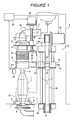
- Figures 1 to 3 show an embodiment of a yarn end retrieving apparatus according to the present invention.
- the yarn end retrieving apparatus has a vertically long machine body 2 located so as to face a conveying path for a bobbin 1, and a yarn releasing device 3 extending from an upper front portion of the machine body 2 to the interior of the machine body 2.
- the yarn releasing device 3 is composed of, for example, a fan 4 that generates a suction air flow, a suction pipe 5 connected to an inlet port of the fan 4, and a pair of nozzles 6 that blows compressed air against the bobbin 1.
- the suction pipe 5, located in the upper front portion of the machine body 2 is bent into an inverse L shape.
- a yarn sensing sensor 7 is located in an inner corner of the folded portion of the suction pipe 5.
- the bobbin 1 includes a winding core 8 with vertically opposite open ends. A lower end of the winding core 8 is supported on a conveying tray 9 provided along a conveying path.
- a cutter device 10 cutting a middle part of a yarn Y sucked out by the yarn releasing device 3 is located at a lower end of the suction pipe 5 which projects forward in the machine body 2.
- An upper end of a flexible cylinder 12 that can be expanded and contracted in a vertical direction is fixed to a cylinder wall 11 that is continuous with a lower end of the cutter device 10.
- a suction cylinder 13 is connected to a lower end of the flexible cylinder 12.
- the cutter device 10 includes a cutter blade 14 and a driving structure (not shown in the drawings) for the cutter blade 14.
- the cutter blade 14 also functions as a shutter that blocks a suction air flow acting on the suction pipe 5.
- the cutter blade 14 having cut the middle part of the yarn Y can block the suction air flow.
- the suction cylinder 13 is formed of a cylinder larger than the size of the diameter of a yarn layer on the bobbin 1.
- the suction cylinder 13 is elevated and lowered between a standby position and a lowered position by a cylinder elevating and lowering device 16 provided inside the machine body 2.
- the cylinder elevating and lowering device 16 is composed of a guide structure and a driving structure that elevates and lowers the suction cylinder 13 along the guide structure.
- the guide structure is composed of a pair of guide shafts (guide members) 17 arranged side by side in a front-back direction, brackets 18 that fixedly support an upper end and a lower end, respectively, of each of the guide shafts 17, and a slider 19 that is slidably guided along both guide shafts 17 so as to be able to elevate and lower.
- the slider 19 is composed of slide blocks 20 slidably guided along the guide shafts 17, a coupling plate 21 that connects the slide blocks 20 together, and a coupling block 22 fixed to the coupling plate 21 between the slide blocks 20.
- the suction cylinder 13 is joined and fixed to the coupling plate 21 via a joining arm 23 projecting from an outer surface of the suction cylinder 13.
- a driving structure is composed of a stepping motor 25 located above the upper bracket 18 and serving as a driving source.
- the driving structure is composed of an upper pulley 26 fixed to an output shaft of the stepping motor 25, a pulley 27 rotatably supported by the lower bracket 18, and a driving belt 28 wound around both pulleys 26, 27.
- Both pulleys 26, 27 are composed of timing pulleys
- the driving belt 28 is composed of a timing belt.
- the driving belt 28 is located so as to sandwich the coupling plate 21 between an upper part and a lower part of the belt. As shown in Figure 3 , one straight-line transition portion of the belt is fixedly clamped to the coupling block 22 of the slider 19 via a seat plate 29 by means of a bolt 30.
- the driving belt 28 is located parallel to the guide shafts 17.
- the straight-line transition portions of the driving belt 28 enable the slider 19 to be drivingly elevated and lowered along the guide shafts 17.
- the suction cylinder 13 is elevated and lowered between the standby position (the position shown in Figure 1 ) above the bobbin 1 and the lowered position (the position shown in Figure 2B ) where the suction cylinder 13 covers the surface of a lower part of the bobbin 1.
- the suction cylinder 13 is held at the standby position at a given distance from the position of an upper end of the bobbin 1 depending on the vertical size of the bobbin 1. Specifically, size data on the bobbin 1 to be processed is pre-input to a control circuit (control means) 43. This determines the standby position of the suction cylinder 13. By counting the number of steps from a reference position taken by the stepping motor 25, the suction cylinder 13 can be held at an appropriate standby position.
- a sensor 33 sensing the shape of the bobbin 1 with the yarn wound therearound is installed on the suction cylinder 13.
- the sensor 33 senses the external shape of the yarn layer on the bobbin 1 to enable determination of whether the bobbin 1 is a full bobbin 1 around which the yarn Y has been fully wound, a half bobbin 1 from which a part of the yarn layer has been unwound by the winder, or a smaller bobbin 1 with a small amount of remaining yarn layer.
- the control circuit 43 Based on pre-input bobbin data, the control circuit 43 automatically determines the standby position of the suction cylinder 13. Concurrently, the cutter device 10 is elevated and lowered by the cutter elevating and lowering device 35. Thus, a cutting position for the yarn Y can be optimized.
- the standby position of the suction cylinder 13 is slightly higher than a position corresponding to the vertical size (height dimension) of the bobbin 1, which is conveyed in an upright condition.
- the standby position is set to be sufficiently higher than the position corresponding to the height dimension of the bobbin 1, all bobbins 1 can be dealt with. However, if the bobbin 1 to be processed has a small vertical size, an unwanted elevating and lowering operation needs to be performed, thus reducing efficiency.
- the standby position of the suction cylinder 13 is set to be higher than the upper end of the bobbin 1 to be processed, by about 10 mm.
- the cutter elevating and lowering device 35 is composed of a stepping motor 36 fixed to the machine body 2, a feed screw shaft 37 rotationally driven by the stepping motor 36, and a female threaded member 38 elevated and lowered by the feeding screw shaft 37.
- An upper end of the feed screw shaft 37 is coupled to the stepping motor 36 via a coupling.
- a lower end of the feed screw shaft 37 is supported by a bracket 39 fixed to the machine body 2.
- the female threaded member 38 is fixed to a coupling frame 40 fixed to the lower end of the cutter device 10.
- the stepping motor 36 is started or stopped based on an instruction signal output by the control circuit 43.
- the cutting position for the yarn Y can be optimized depending on a change in the vertical size of the bobbin 1.
- the cutting position for the yarn Y is set such that the total length of the yarn Y sucked into the winding core 8 is slightly smaller than the vertical size of the bobbin 1.
- the cutter blade 14 is operatively displaced to a cutting standby position.
- the cutter blade 14 blocking the suction pipe 5 is thus displaced to a passage open position. Consequently, the suction pipe 5 and the suction cylinder 13 communicate with each other via the cutter device 10 and the flexible cylinder 12 so that a suction air flow can act on the suction cylinder 13.
- the stepping motor 25 is started based on an instruction signal output by the control circuit 43.
- the suction cylinder 13 is lowered via the slider 19 at a predetermined speed.
- an upward suction air flow acts on a peripheral surface of the bobbin 1.
- the yarn end being blown upward by air through the nozzles 6 is sucked into the suction pipe 5 via the suction cylinder 13, the flexible cylinder 12, and the cutter device 10 as shown in Figure 2B .
- the sensor 7 senses that the yarn Y has been sucked into the suction pipe 5. Then, as shown in Figure 2C , the stepping motor 25 is reversely driven to return the suction pipe 13 to the standby position. However, if the yarn Y cannot be sensed by the sensor 7 even though the lower end of the suction cylinder 13 has reached the lower end of the bobbin 1, the suction cylinder 13 is returned to the standby position and then lowered again to suck the yarn using a suction air flow. The suction cylinder 13 attempts to suck the yarn a plurality of times. If the attempts have failed to allow the sensor 7 to output a signal indicating that the yarn Y has been sensed, the stopper for the conveying tray 9 is released to allow the bobbin 1 to be discharged from the yarn setup position.
- the conveying tray 9 is stopped and held, and the lower part of the bobbin 1 is pressed and held by the presser lever as described above. Moreover, compressed air is blown out from the nozzles 6 to blow the yarn Y to above the bobbin 1.
- the suction cylinder 13 is lowered quickly to a winding position for the yarn Y. The suction cylinder 13 is then lowered at the predetermined speed as is the case of the full bobbin 1 with a suction air flow acting on the surface of the bobbin 1.
- the standby position of the suction cylinder 13 can be automatically determined. Furthermore, the suction cylinder 13 can be accurately held at the standby position by the cylinder elevating and lowering device 16. The standby position can be accurately changed in association with a lot change.
- the present yarn end retrieving apparatus allows the setup thereof to be quickly and easily changed in association with the lot change.
- an elevating and lowering speed and an elevating and lowering stroke for the suction cylinder 13 can be freely set.
- the speed at which the suction cylinder 13 is elevated and returned to the standby position can be set to be higher than that at which the suction cylinder 13 is lowered to suck out the yarn Y.
- the cylinder elevating and lowering device 16 configured as described above enable s a reduction in the time required for the yarn setup process. If required, the s uction cylinder 13 can be stopped and held at a predetermined height to allow the suction air flow to concentrate on the surface of the bobbin 1.
- the cutting position for the yarn Y can be optimized in association with the vertical size of the bobbin 1 by allowing the cutter elevating and lowering device 35 to elevate and lower the cutter device 10 concurrently with the automatic setting of the standby position of the suction cylinder 13.
- the end of the yarn Y sucked into the winding core 8 can be reliably prevented from being sucked into the yarn sucking device 45.
- the yarn Y sucked into the winding core 8 is prevented from sticking out from the winding core 8 during the conveyance of the bobbin as a result of the insufficient length of the sucked yarn Y.
- the driving structure for the cylinder elevating and lowering device 16 is composed of the vertical pair of pulleys 26, 27, the driving belt 28, and others.
- the driving structure can be composed of a feed screw shaft, a female threaded member, and others as in the case of the cutter elevating and lowering device 35.
- the driving structure and the cutter elevating and lowering device can be composed of a rack supported and guided so as to be slidable in the vertical direction, a pinion that drives the rack in the vertical direction, and a stepping motor that rotationally drives the pinion.
Landscapes
- Engineering & Computer Science (AREA)
- Textile Engineering (AREA)
- Replacing, Conveying, And Pick-Finding For Filamentary Materials (AREA)
- Spinning Or Twisting Of Yarns (AREA)
- Coiling Of Filamentary Materials In General (AREA)
Applications Claiming Priority (1)
| Application Number | Priority Date | Filing Date | Title |
|---|---|---|---|
| JP2008088646A JP2009242027A (ja) | 2008-03-28 | 2008-03-28 | ボビンの口出し装置 |
Publications (2)
| Publication Number | Publication Date |
|---|---|
| EP2105401A2 true EP2105401A2 (fr) | 2009-09-30 |
| EP2105401A3 EP2105401A3 (fr) | 2012-08-15 |
Family
ID=40785537
Family Applications (1)
| Application Number | Title | Priority Date | Filing Date |
|---|---|---|---|
| EP09003055A Withdrawn EP2105401A3 (fr) | 2008-03-28 | 2009-03-03 | Appareil d'extraction d'extremité de fil |
Country Status (3)
| Country | Link |
|---|---|
| EP (1) | EP2105401A3 (fr) |
| JP (1) | JP2009242027A (fr) |
| CN (1) | CN101544326A (fr) |
Cited By (5)
| Publication number | Priority date | Publication date | Assignee | Title |
|---|---|---|---|---|
| CN102041589A (zh) * | 2009-10-24 | 2011-05-04 | 欧瑞康纺织有限及两合公司 | 用于自由端转子纺纱装置的接头方法 |
| ITUA20162101A1 (it) * | 2016-03-30 | 2017-09-30 | Savio Macch Tessili Spa | Apparecchiatura per catturare il bandolo di una spola |
| EP3748054A1 (fr) * | 2019-06-06 | 2020-12-09 | Lakshmi Machine Works Ltd. | Appareil d'inclinaison de guide-fil pour ensemble de rattachage automatique de fil |
| EP3608267A4 (fr) * | 2017-04-07 | 2020-12-23 | Murata Machinery, Ltd. | Dispositif de traitement de bobines |
| DE102021118599B4 (de) * | 2020-07-17 | 2026-01-22 | Qingdao Hongda Textile Machinery Co., Ltd. | Wannen-Fadenspulmaschine und Fadenspulverfahren |
Families Citing this family (14)
| Publication number | Priority date | Publication date | Assignee | Title |
|---|---|---|---|---|
| CN102691150A (zh) * | 2012-05-28 | 2012-09-26 | 青岛宏大纺织机械有限责任公司 | 一种纱管托盘 |
| CN104003253A (zh) * | 2014-06-19 | 2014-08-27 | 山东魏桥创业集团有限公司 | 一种自动络筒cbf挑头器找头装置 |
| CN104178996A (zh) * | 2014-08-08 | 2014-12-03 | 常州市日发精密机械厂 | 防纱线回弹的纱线切断器 |
| CN106115371B (zh) * | 2016-08-11 | 2018-11-13 | 常州长荣纺织有限公司 | 管纱自动投送装置 |
| CN106276419A (zh) * | 2016-10-21 | 2017-01-04 | 青岛宏大纺织机械有限责任公司 | 自动络筒机生头机构及生头方法 |
| JP2018177419A (ja) * | 2017-04-07 | 2018-11-15 | 村田機械株式会社 | ボビン処理装置 |
| CN108423481A (zh) * | 2018-02-12 | 2018-08-21 | 铜陵松宝智能装备股份有限公司 | 一种纱管包脚纱线退绕装置及退绕方法 |
| CN108439071A (zh) * | 2018-02-12 | 2018-08-24 | 铜陵松宝智能装备股份有限公司 | 一种纱管生头装置及生头方法 |
| CN108423493A (zh) * | 2018-02-12 | 2018-08-21 | 铜陵松宝智能装备股份有限公司 | 一种纱管线头捕捉装置及捕捉方法 |
| CN108408490A (zh) * | 2018-02-12 | 2018-08-17 | 铜陵松宝智能装备股份有限公司 | 一种纱管纱线生头设备及方法 |
| CN108975073A (zh) * | 2018-07-18 | 2018-12-11 | 铜陵松宝智能装备股份有限公司 | 一种用于络筒纱管库的牵头装置及络筒纱管库 |
| DE102019107378A1 (de) * | 2019-03-22 | 2020-09-24 | Saurer Spinning Solutions Gmbh & Co. Kg | Verfahren zur Kopsvorbereitung |
| JP2020200170A (ja) * | 2019-06-12 | 2020-12-17 | 村田機械株式会社 | 糸処理方法及び糸処理装置 |
| CN115571731B (zh) * | 2022-11-03 | 2026-04-14 | 深圳市微埃智能科技有限公司 | 刮刀、刮刀装置、刮线装置及投纱机器人 |
Citations (2)
| Publication number | Priority date | Publication date | Assignee | Title |
|---|---|---|---|---|
| JPH0797142A (ja) | 1993-09-24 | 1995-04-11 | Murata Mach Ltd | 口出し装置 |
| JPH08324892A (ja) | 1995-05-31 | 1996-12-10 | W Schlafhorst Ag & Co | 精紡コップ表面から糸端部を解離する装置 |
Family Cites Families (3)
| Publication number | Priority date | Publication date | Assignee | Title |
|---|---|---|---|---|
| EP0805118B1 (fr) * | 1996-05-02 | 2001-11-28 | W. SCHLAFHORST AG & CO. | Tête de bobinage pour la production des bobines croisées pour machines textiles |
| DE102005018381A1 (de) * | 2005-04-21 | 2006-10-26 | Saurer Gmbh & Co. Kg | Spulstelle einer Kreuzspulen herstellenden Textilmaschine |
| DE102006044646A1 (de) * | 2006-09-21 | 2008-04-03 | Oerlikon Textile Gmbh & Co. Kg | Arbeitsstelle einer Kreuzspulen herstellenden Textilmaschine |
-
2008
- 2008-03-28 JP JP2008088646A patent/JP2009242027A/ja active Pending
-
2009
- 2009-03-03 EP EP09003055A patent/EP2105401A3/fr not_active Withdrawn
- 2009-03-19 CN CN200910128459A patent/CN101544326A/zh active Pending
Patent Citations (2)
| Publication number | Priority date | Publication date | Assignee | Title |
|---|---|---|---|---|
| JPH0797142A (ja) | 1993-09-24 | 1995-04-11 | Murata Mach Ltd | 口出し装置 |
| JPH08324892A (ja) | 1995-05-31 | 1996-12-10 | W Schlafhorst Ag & Co | 精紡コップ表面から糸端部を解離する装置 |
Cited By (7)
| Publication number | Priority date | Publication date | Assignee | Title |
|---|---|---|---|---|
| CN102041589A (zh) * | 2009-10-24 | 2011-05-04 | 欧瑞康纺织有限及两合公司 | 用于自由端转子纺纱装置的接头方法 |
| CN102041589B (zh) * | 2009-10-24 | 2014-07-30 | 索若德国两合股份有限公司 | 用于自由端转子纺纱装置的接头方法 |
| ITUA20162101A1 (it) * | 2016-03-30 | 2017-09-30 | Savio Macch Tessili Spa | Apparecchiatura per catturare il bandolo di una spola |
| EP3225576A1 (fr) * | 2016-03-30 | 2017-10-04 | Savio Macchine Tessili S.p.A. | Appareil de capture de l'extrémité d'une bobine de fil |
| EP3608267A4 (fr) * | 2017-04-07 | 2020-12-23 | Murata Machinery, Ltd. | Dispositif de traitement de bobines |
| EP3748054A1 (fr) * | 2019-06-06 | 2020-12-09 | Lakshmi Machine Works Ltd. | Appareil d'inclinaison de guide-fil pour ensemble de rattachage automatique de fil |
| DE102021118599B4 (de) * | 2020-07-17 | 2026-01-22 | Qingdao Hongda Textile Machinery Co., Ltd. | Wannen-Fadenspulmaschine und Fadenspulverfahren |
Also Published As
| Publication number | Publication date |
|---|---|
| EP2105401A3 (fr) | 2012-08-15 |
| JP2009242027A (ja) | 2009-10-22 |
| CN101544326A (zh) | 2009-09-30 |
Similar Documents
| Publication | Publication Date | Title |
|---|---|---|
| EP2105401A2 (fr) | Appareil d'extraction d'extremité de fil | |
| JP6692425B2 (ja) | ロール搬送装置およびロール搬送方法 | |
| EP2738129B1 (fr) | Machine de bobinage de fil et machine textile la comprenant | |
| EP2502863A2 (fr) | Unité d'enroulement, enrouleur automatique et procédé d'alignement de bobine d'alimentation de fil | |
| CN102730482A (zh) | 纱线卷绕机及纱线引出方法 | |
| EP2105397B1 (fr) | Dispositif d'assistance au déroulement pour bobinoir automatique | |
| JP2009149404A (ja) | 解舒補助装置及びそれを備える自動ワインダ | |
| JP5101363B2 (ja) | チューブ切断装置 | |
| US9623991B2 (en) | Automatic packing machine | |
| JP2005119880A (ja) | テープ巻取装置 | |
| EP2738127A2 (fr) | Machine de renvideur de fil et procédé de retrait de fil | |
| JP5081033B2 (ja) | チューブ切断装置 | |
| CN111374378A (zh) | 口罩加工机及鼻梁条定位置入工艺 | |
| JP5149680B2 (ja) | コイル搬出装置 | |
| JP5286060B2 (ja) | 紙葉類供給装置 | |
| EP2669229A2 (fr) | Dispositif de décharge d'emballage et machine de bobinage de fil | |
| EP0256823A1 (fr) | Dispositif d'alimentation | |
| EP2738128A2 (fr) | Machine de renvideur de fil | |
| JP5073551B2 (ja) | チューブ切断装置 | |
| CN106904318B (zh) | 食品容器供给装置 | |
| JPH07211572A (ja) | 巻線機のフィルム巻付機構 | |
| JP5101364B2 (ja) | チューブ切断装置 | |
| US20260048576A1 (en) | Threadlike adhesive sticking apparatus and method of sticking threadlike adhesive | |
| JP6167322B2 (ja) | ペーパーホルダー | |
| JP2009233807A (ja) | チューブ切断装置 |
Legal Events
| Date | Code | Title | Description |
|---|---|---|---|
| PUAI | Public reference made under article 153(3) epc to a published international application that has entered the european phase |
Free format text: ORIGINAL CODE: 0009012 |
|
| AK | Designated contracting states |
Kind code of ref document: A2 Designated state(s): AT BE BG CH CY CZ DE DK EE ES FI FR GB GR HR HU IE IS IT LI LT LU LV MC MK MT NL NO PL PT RO SE SI SK TR |
|
| AX | Request for extension of the european patent |
Extension state: AL BA RS |
|
| PUAL | Search report despatched |
Free format text: ORIGINAL CODE: 0009013 |
|
| AK | Designated contracting states |
Kind code of ref document: A3 Designated state(s): AT BE BG CH CY CZ DE DK EE ES FI FR GB GR HR HU IE IS IT LI LT LU LV MC MK MT NL NO PL PT RO SE SI SK TR |
|
| AX | Request for extension of the european patent |
Extension state: AL BA RS |
|
| RIC1 | Information provided on ipc code assigned before grant |
Ipc: B65H 67/08 20060101AFI20120710BHEP |
|
| STAA | Information on the status of an ep patent application or granted ep patent |
Free format text: STATUS: THE APPLICATION HAS BEEN WITHDRAWN |
|
| 18W | Application withdrawn |
Effective date: 20121004 |