EP2105535A2 - Dispositif de fraisage destiné au traitement d'une surface de piste de ski - Google Patents
Dispositif de fraisage destiné au traitement d'une surface de piste de ski Download PDFInfo
- Publication number
- EP2105535A2 EP2105535A2 EP09004089A EP09004089A EP2105535A2 EP 2105535 A2 EP2105535 A2 EP 2105535A2 EP 09004089 A EP09004089 A EP 09004089A EP 09004089 A EP09004089 A EP 09004089A EP 2105535 A2 EP2105535 A2 EP 2105535A2
- Authority
- EP
- European Patent Office
- Prior art keywords
- milling
- housing
- snow
- baffles
- guide elements
- Prior art date
- Legal status (The legal status is an assumption and is not a legal conclusion. Google has not performed a legal analysis and makes no representation as to the accuracy of the status listed.)
- Withdrawn
Links
Images


Classifications
-
- E—FIXED CONSTRUCTIONS
- E01—CONSTRUCTION OF ROADS, RAILWAYS, OR BRIDGES
- E01H—STREET CLEANING; CLEANING OF PERMANENT WAYS; CLEANING BEACHES; DISPERSING OR PREVENTING FOG IN GENERAL CLEANING STREET OR RAILWAY FURNITURE OR TUNNEL WALLS
- E01H4/00—Working on surfaces of snow or ice in order to make them suitable for traffic or sporting purposes, e.g. by compacting snow
- E01H4/02—Working on surfaces of snow or ice in order to make them suitable for traffic or sporting purposes, e.g. by compacting snow for sporting purposes, e.g. preparation of ski trails; Construction of artificial surfacings for snow or ice sports ; Trails specially adapted for on-the-snow vehicles, e.g. devices adapted for ski-trails
Definitions
- the invention relates to a milling device for processing a snow slope surface, which is attachable to a snow groomer, with at least one milling shaft, which is surrounded by a milling housing and driven by a motor, and with a rear finisher for smoothing the slope surface, which adjoins the back of the milling housing.
- Such a snow milling device is well known in snow groomers that are used in ski resorts.
- the well-known Fräs worn is designed as a rear attachment to the snowcat.
- An attachment frame which is connectable to a rear carrier of the snow groomer, carries a milling housing, in which two or three coaxially juxtaposed cutter shafts are provided.
- the milling housing is designed in two or three parts, so that a separate milling space is available for each milling shaft.
- a rear finisher is provided to the milling housing, which smoothes the milled snow and thus forms the machined slope surface.
- the object of the invention is to provide a milling device of the type mentioned, which allows a good quality of the machined runway surface regardless of the type and amount of snow to be processed.
- the milling housing is provided on one of the at least one milling shaft facing inside of the housing with guide elements that a steering of the milling shaft detected and thrown into the milling housing snow amounts in particular outward or inward - relative to a longitudinal axis of the milling housing - make.
- amount of snow means hard and soft snow as well as ice or snow / ice mixture.
- the solution of the invention is particularly suitable for a rear attachable to a snow groomer milling device, which is also referred to as a rear grinder. Corresponding caterpillars of the snow groomer already loosen the ground before the milling function of the rear tiller begins.
- the guide elements are movably arranged and adjustable by at least one adjusting device. Depending on the type and size of snow to be milled, an adjustment of the guide elements is carried out in order to allow a consistent quality of the machined slope surface under different snow conditions.
- the guide elements are set so that at large fresh snow amounts of snow from the outer sides of the milling device, that is, transported from the lateral areas of the at least one milling shaft toward the center.
- the guide elements are preferably aligned so radially to the axis of rotation of the milling shaft that the processed snow is ejected at about the same axial height as at the height of its intake as still to be processed amount of snow.
- the guide elements can preferably be adjusted so that the snow is transported within the milling housing from the center of increased to the outer sides.
- the adjusting device is designed mechanically, electrically, pneumatically or hydraulically.
- this list also includes a combination of these functions, in particular an electromechanical design.
- this can be assisted in particular by a threaded spindle or rack and pinion drive.
- the adjusting device preferably comprises at least one corresponding pressure medium cylinder such as a pneumatic or a hydraulic cylinder.
- a control unit which controls the actuating device via at least one control line.
- the control unit is preferably associated with the milling device.
- At least two guide elements are connected to one another via at least one coupling element for joint adjustability. This makes it possible to adjust a plurality of guide elements in groups or completely together by the adjusting device.
- the guide elements are designed as guide webs, in particular as baffles, which protrude at least substantially at right angles from the inside of the housing.
- a milling device after the Fig. 1 and 2 in the form of a rear tiller 1 is provided for rear attachment to a tracked vehicle in the form of a snowcat, which is not shown in detail.
- the snow groomer has on the rear side a rear implement carrier with which the rear tiller 1 can be connected via a coupling region 2 in a basically known manner.
- the rear tiller 1 has a support frame 4, on which a milling housing 5 is provided.
- coaxial side by side two milling shafts 3 are rotatably mounted, which are hydraulically driven in a basically known manner.
- a tail finisher 6 serving for smoothing the processed piste surface adjoins the milling housing 5.
- baffles 7 Inside the two milling housing a plurality of guide elements in the form of baffles 7 are provided, which extend in a space between the inner wall of the milling housing 5 and the outer periphery of the respective Fräswelle 3.
- the guide plates 7 project approximately at right angles to the inner wall of the milling housing 5.
- Each baffle 7 is sword-like curved, wherein the curvature is tracked in about the curvature of the inner wall of the cutter housing 5.
- the baffles 7 are aligned in groups parallel to each other.
- the baffles 7 are relative to the milling housing pivotally mounted adjustable.
- a bearing assembly 8 is provided for each group of baffles 7, which allows the pivoting movement of the group of guide elements 7.
- the baffles may also be mounted individually adjustable. It is also possible that the corresponding baffles are not aligned parallel to each other, but at an angle to each other. In non-illustrated embodiments of the invention, other types of adjustability of the baffles are provided. Thus, the baffles do not necessarily have to be mounted pivotably. Rather, they can also be mounted adjustably along curved paths.
- each an adjusting device 10 is provided in the region of each milling shaft 3, which is at least partially outside the cutter housing 5.
- the adjusting device 10 has adjusting rods 9 which are assigned to the corresponding groups of baffles 7.
- Each control rod 9 is articulated to the respective group of baffles 7 such that a movement of the corresponding control rod 9 causes a pivoting movement of the group of baffles 7.
- the articulation points of the control rod 9 are arranged on the baffles 7 at a distance from the bearing points of the baffles 7 in order to form corresponding lever arms.
- the actuator 10 is provided with a hydraulic cylinder, which hydraulically causes the movement of the control rod 9.
- the arrangement is in Fig. 2 recognizable, since there for reasons of clarity, the milling shaft 3 has been removed in the corresponding representation.
- An identical arrangement is in the area of the right Fräswelle 3 at Fig. 2 intended.
- the opposite groups of baffles 7 in the region of the milling housing 5 can according to the illustration according to Fig. 2 mirror-symmetrical to a vertical one Center longitudinal plane of the milling housing 5 aligned and adjustable. The vertical center longitudinal plane runs in the towing direction of the rear tiller and thus in the direction of travel of the rear tiller 1.
- a control unit S is provided ( Fig. 1 ), which can be controlled by the tracked vehicle.
- the control unit S is in the illustrated embodiment, an electro-hydraulic control unit that transmits electronic or electrical control commands of the vehicle control to the hydraulic actuator 10. This makes it possible to operate from the cab from the adjustment of the baffles 7. It is also possible to effect a fully automatic adjustment of the baffles by means of a corresponding sensor, detects the nature and depth of the snow to be processed and causes a proper adjustment of the baffles characterized in that the signals of the sensors are evaluated and converted into corresponding control commands.
- baffles By adjusting the baffles, it is possible to deflect absorbed amounts of snow defined between the cutter shaft and inner wall of the cutter housing and so selectively defines a distribution or leadership of snow with a component in the longitudinal direction of the cutter housing 5 to the center or to the outside, ie along a rotation axis of the Fräswelle. 3 , to achieve.
- Fig. 2 can be transported through the mirror-symmetrical arrangement of the left and right group of baffles 7 each cutter housing 5, the amounts of snow within the cutter housing either to the axial center of the cutter housing 5 or to the axial outer sides of the cutter housing 5.
- baffles 7 When aligned radially to the axis of rotation D of the respective milling shaft 3 baffles 7 finally there is no axial displacement of the amount of snow within the milling housing, but the recorded snow is led out at about the same axial height again from the milling housing on which it was taken.
- the embodiment according to Fig. 3 corresponds in all essential parts and functions of the embodiments described above according to the Fig. 1 and 2 , so that only the differences are discussed below.
- Significant difference in the embodiment according to Fig. 3 it is that the baffles 7 are mounted pivotably on the inner wall of the cutter housing 5 via individual bearing points 8a. They are therefore not summarized in groups on a common bearing assembly 8, as in the embodiment according to Fig. 2 the case is.
- the baffles 7 nevertheless form groups, since they are articulated in groups via a corresponding adjusting rod 9 of the adjusting device 10.
- the linkage corresponds functionally to the previously already using the Fig. 1 and 2 described articulation.
- baffles which in the embodiments according to the Fig. 1 to 3 are shown graphically for each group, are merely exemplary and schematic, but not to be understood as limiting. Only for reasons of clarity, these examples were provided with three baffles for each group. It is also not necessary that the baffles have equal distances to each other. It is provided in other embodiments of the invention that the distances between the baffles 7 to each other over the axial length of the cutter housing 5 change. It is also possible to arrange baffles individually or in pairs or in groups of more than three baffles.
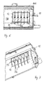
- FIGS. 4 to 7 shows a milling device similar to the previously described embodiments. To avoid repetition, the differences to the previously described embodiments will be discussed below. function DC Parts and arrangements are provided with the same reference numerals with the addition of the letter b.
- the milling device after the FIGS. 4 to 7 comprises a group of guide elements in the form of baffles 7b, which is arranged in an offset to a center of the cutter housing 5b outwardly portion of the cutter housing 5b.
- the baffles 7b are combined via a mounting plate 12 to a mounting assembly as Vormontagetechnik.
- the mounting plate 12 has bearing mounts for corresponding bearing pin 13 of the total of five baffles 7b.
- the bearing receivers and the bearing journals 13 are aligned in an alignment parallel to a rotation axis of the milling shaft.
- the pre-assembly and thus also the mounting plate 12 is, as based on the FIGS. 4 and 5 can be seen, arranged in the region of the cutter shaft 3b on the inside of the cutter housing 5b.
- the baffles 7b are designed swordlike similar to a circumferential contour of the milling shaft 3b.
- the mounting plate 12 is fixed either by means of releasable fastening means or with the aid of integral connections such as a weld or the like on the inside of the cutter housing 5b.
- the bearing journals 13 project from the mounting plate 12 to the side opposite the baffles 7b and pass through corresponding openings of the milling housing.
- unspecified pivot lever 13 are arranged on the bearing pin, which are connected to each other via a common lever 10b.
- the pivot lever and the lever 10b form the adjusting device according to the invention.
- the adjusting lever is displaceable by means of a hand lever 11 to the left or to the right, whereby the pivot levers are pivoted together and parallel to each other. This in turn leads to a corresponding common pivoting of the baffles 7b.
- a locking pin 14 is provided in the region of an outer end face of the milling housing 5b.
- the hand lever 11 has a Lochrast réelle on the locking pin is tuned to engage over the locking pin 14 in the corresponding position.
- five locking receptacles are provided which allow a locking of the hand lever 11 in five different positions in the region of the locking pin 14.
- five different positions of the adjusting lever 10b are inevitably adjustable, since the hand lever 11 is articulated at one end of the adjusting lever 10b. This in turn leads to five different pivot positions for the baffles 7b.
- the hand lever 11 is replaced by an actuating device which is connected to a hydraulic, pneumatic or electric actuator. This makes it possible to carry out an automatic or remote-controlled adjustability similar to the previously described embodiments.
Landscapes
- Engineering & Computer Science (AREA)
- Architecture (AREA)
- Civil Engineering (AREA)
- Structural Engineering (AREA)
- Road Repair (AREA)
- Cleaning Of Streets, Tracks, Or Beaches (AREA)
- Milling Processes (AREA)
Applications Claiming Priority (1)
| Application Number | Priority Date | Filing Date | Title |
|---|---|---|---|
| DE200810016915 DE102008016915B4 (de) | 2008-03-26 | 2008-03-26 | Fräseinrichtung zur Bearbeitung einer Schneepistenoberfläche |
Publications (2)
| Publication Number | Publication Date |
|---|---|
| EP2105535A2 true EP2105535A2 (fr) | 2009-09-30 |
| EP2105535A3 EP2105535A3 (fr) | 2010-09-08 |
Family
ID=40810280
Family Applications (1)
| Application Number | Title | Priority Date | Filing Date |
|---|---|---|---|
| EP09004089A Withdrawn EP2105535A3 (fr) | 2008-03-26 | 2009-03-23 | Dispositif de fraisage destiné au traitement d'une surface de piste de ski |
Country Status (2)
| Country | Link |
|---|---|
| EP (1) | EP2105535A3 (fr) |
| DE (1) | DE102008016915B4 (fr) |
Cited By (3)
| Publication number | Priority date | Publication date | Assignee | Title |
|---|---|---|---|---|
| EP2479344A1 (fr) * | 2011-01-21 | 2012-07-25 | BOMAG GmbH | Caisson de rotor pour une machine à fraiser le sol dotée d'un dispositif de guidage pour des produits de fraisage et machine à fraiser le sol dotée d'un tel caisson de rotor |
| EP2314773A3 (fr) * | 2009-10-13 | 2012-09-26 | Kässbohrer Geländefahrzeug AG | Appareil de traitement de pistes remorqué |
| CN113863106A (zh) * | 2021-11-08 | 2021-12-31 | 江苏徐工工程机械研究院有限公司 | 铣刨装置和铣刨机 |
Families Citing this family (1)
| Publication number | Priority date | Publication date | Assignee | Title |
|---|---|---|---|---|
| DE102024123330B4 (de) | 2024-08-15 | 2026-03-26 | Kässbohrer Geländefahrzeug Aktiengesellschaft | Heckfräse zur Schneeflächenbearbeitung |
Family Cites Families (6)
| Publication number | Priority date | Publication date | Assignee | Title |
|---|---|---|---|---|
| DE843101C (de) * | 1945-05-28 | 1952-07-03 | Schneeraeumungs Maschinen A G | Schneeraeummaschine |
| DE2922326C2 (de) * | 1979-06-01 | 1984-04-19 | Paul 2870 Delmenhorst Vollmar | Schneefräse |
| US4860465A (en) * | 1988-01-04 | 1989-08-29 | Brandt Claude R | Snow grooming vehicle and attachments |
| DE29703678U1 (de) * | 1997-02-28 | 1998-06-25 | Kässbohrer Geländefahrzeug GmbH, 89250 Senden | Pistenpflegevorrichtung |
| DE10333423A1 (de) * | 2003-07-17 | 2005-02-24 | Kässbohrer Geländefahrzeug AG | Pistenpflegevorrichtung |
| DE102004059821B4 (de) * | 2004-12-03 | 2010-11-25 | Kässbohrer Geländefahrzeug AG | Pistenpflegevorrichtung zum Anbau an ein Fahrzeug |
-
2008
- 2008-03-26 DE DE200810016915 patent/DE102008016915B4/de not_active Expired - Fee Related
-
2009
- 2009-03-23 EP EP09004089A patent/EP2105535A3/fr not_active Withdrawn
Cited By (6)
| Publication number | Priority date | Publication date | Assignee | Title |
|---|---|---|---|---|
| EP2314773A3 (fr) * | 2009-10-13 | 2012-09-26 | Kässbohrer Geländefahrzeug AG | Appareil de traitement de pistes remorqué |
| US8443529B2 (en) | 2009-10-13 | 2013-05-21 | Kaessbohrer Gelaendefahrzeug Ag | Towed piste processing implement |
| EP2479344A1 (fr) * | 2011-01-21 | 2012-07-25 | BOMAG GmbH | Caisson de rotor pour une machine à fraiser le sol dotée d'un dispositif de guidage pour des produits de fraisage et machine à fraiser le sol dotée d'un tel caisson de rotor |
| CN102628250A (zh) * | 2011-01-21 | 2012-08-08 | 宝马格有限公司 | 带有铣刨料引导装置的地面铣刨机的转子箱及带有该转子箱的铣刨机 |
| CN113863106A (zh) * | 2021-11-08 | 2021-12-31 | 江苏徐工工程机械研究院有限公司 | 铣刨装置和铣刨机 |
| CN113863106B (zh) * | 2021-11-08 | 2023-03-14 | 江苏徐工工程机械研究院有限公司 | 铣刨装置和铣刨机 |
Also Published As
| Publication number | Publication date |
|---|---|
| DE102008016915A1 (de) | 2009-10-08 |
| DE102008016915B4 (de) | 2010-04-01 |
| EP2105535A3 (fr) | 2010-09-08 |
Similar Documents
| Publication | Publication Date | Title |
|---|---|---|
| DE68903121T2 (de) | Verbesserung an landmaschinen fuer die futterernte. | |
| EP2339072A2 (fr) | Appareil de traitement de sol doté d'un agencement d'arbres de travail entraînés | |
| DE102008016915B4 (de) | Fräseinrichtung zur Bearbeitung einer Schneepistenoberfläche | |
| EP0194991A2 (fr) | Machine pour le travail du sol | |
| EP1925746B1 (fr) | Dispositif d'entretien de pistes pour un véhicule à chenilles | |
| DE102012021378A1 (de) | Baumaschine zum Bearbeiten von Bodenoberflächen mit einer Schwenkvorrichtung für eine Fahreinrichtung, Schwenkvorrichtung sowie Verfahren zum Verschwenken einer Fahreinrichtung einer Baumaschine | |
| DE19534695A1 (de) | An einem Schlepper ansetzbares Heckmähwerk | |
| EP1859665B1 (fr) | Machine agricole tractée à grande largeur de travail | |
| DE102006056050A1 (de) | Gutführvorrichtung | |
| EP1754832A2 (fr) | Dispositif pour le traçage de pistes de ski et véhicule pour l'entretien des pistes de ski comportant au moins un tel dispositif | |
| EP2011383B1 (fr) | Moissonneuse dotée d'un dispositif de coupe | |
| EP2055172A2 (fr) | Machine agricole | |
| EP2374694B1 (fr) | Dispositif de guidage pour un engin autopropulseur | |
| EP1486404B1 (fr) | Machine de travail automotrice à essieu unique pour l'entraînement d'outils de travail et leur déplacement en poussée ou en traction | |
| DE102022110404A1 (de) | Anbaugerät zur feldbearbeitung | |
| EP2172092B1 (fr) | Appareil de traitement des sols | |
| DE202020107353U1 (de) | Bodenwalze | |
| EP4324986B1 (fr) | Fraise arrière pour une dameuse et dameuse | |
| DE102024123330B4 (de) | Heckfräse zur Schneeflächenbearbeitung | |
| DE102004059821B4 (de) | Pistenpflegevorrichtung zum Anbau an ein Fahrzeug | |
| AT388638B (de) | Bearbeitungsgeraet | |
| DE202004006301U1 (de) | Fräsvorrichtung für ein Fahrzeug | |
| EP0509307B1 (fr) | Tondeuse attachable à un tracteur au moyen d'une barre de traction | |
| DE102006008547B3 (de) | Schneeschleudervorrichtung zum Anbau an ein Fahrzeug | |
| DE69907053T2 (de) | Bodenbearbeitungsmaschine mit seitlich aus-und einfaltbaren Werkzeugen |
Legal Events
| Date | Code | Title | Description |
|---|---|---|---|
| PUAI | Public reference made under article 153(3) epc to a published international application that has entered the european phase |
Free format text: ORIGINAL CODE: 0009012 |
|
| AK | Designated contracting states |
Kind code of ref document: A2 Designated state(s): AT BE BG CH CY CZ DE DK EE ES FI FR GB GR HR HU IE IS IT LI LT LU LV MC MK MT NL NO PL PT RO SE SI SK TR |
|
| AX | Request for extension of the european patent |
Extension state: AL BA RS |
|
| PUAL | Search report despatched |
Free format text: ORIGINAL CODE: 0009013 |
|
| AK | Designated contracting states |
Kind code of ref document: A3 Designated state(s): AT BE BG CH CY CZ DE DK EE ES FI FR GB GR HR HU IE IS IT LI LT LU LV MC MK MT NL NO PL PT RO SE SI SK TR |
|
| AX | Request for extension of the european patent |
Extension state: AL BA RS |
|
| AKY | No designation fees paid | ||
| STAA | Information on the status of an ep patent application or granted ep patent |
Free format text: STATUS: THE APPLICATION IS DEEMED TO BE WITHDRAWN |
|
| 18D | Application deemed to be withdrawn |
Effective date: 20110309 |