EP2107183A2 - Dispositif pour supporter au moins un panneau de verre - Google Patents
Dispositif pour supporter au moins un panneau de verre Download PDFInfo
- Publication number
- EP2107183A2 EP2107183A2 EP09003581A EP09003581A EP2107183A2 EP 2107183 A2 EP2107183 A2 EP 2107183A2 EP 09003581 A EP09003581 A EP 09003581A EP 09003581 A EP09003581 A EP 09003581A EP 2107183 A2 EP2107183 A2 EP 2107183A2
- Authority
- EP
- European Patent Office
- Prior art keywords
- rail
- glass plate
- glass
- cavity
- glass plates
- Prior art date
- Legal status (The legal status is an assumption and is not a legal conclusion. Google has not performed a legal analysis and makes no representation as to the accuracy of the status listed.)
- Withdrawn
Links
- 239000011521 glass Substances 0.000 title claims abstract description 47
- 239000000853 adhesive Substances 0.000 claims abstract description 7
- 230000001070 adhesive effect Effects 0.000 claims abstract description 7
- 239000007788 liquid Substances 0.000 claims abstract description 7
- 239000005336 safety glass Substances 0.000 claims abstract description 3
- 239000007769 metal material Substances 0.000 claims abstract 2
- 229920001187 thermosetting polymer Polymers 0.000 claims description 3
- 238000004519 manufacturing process Methods 0.000 description 4
- 239000002184 metal Substances 0.000 description 4
- 238000010348 incorporation Methods 0.000 description 2
- 238000009434 installation Methods 0.000 description 2
- 239000012790 adhesive layer Substances 0.000 description 1
- 230000015572 biosynthetic process Effects 0.000 description 1
- 239000002131 composite material Substances 0.000 description 1
- 230000007547 defect Effects 0.000 description 1
- 230000001419 dependent effect Effects 0.000 description 1
- 238000011161 development Methods 0.000 description 1
- 230000018109 developmental process Effects 0.000 description 1
- 238000001125 extrusion Methods 0.000 description 1
- 239000000463 material Substances 0.000 description 1
- 230000000007 visual effect Effects 0.000 description 1
Images

Classifications
-
- E—FIXED CONSTRUCTIONS
- E04—BUILDING
- E04F—FINISHING WORK ON BUILDINGS, e.g. STAIRS, FLOORS
- E04F11/00—Stairways, ramps, or like structures; Balustrades; Handrails
- E04F11/18—Balustrades; Handrails
- E04F11/181—Balustrades
- E04F11/1851—Filling panels, e.g. concrete, sheet metal panels
-
- E—FIXED CONSTRUCTIONS
- E04—BUILDING
- E04F—FINISHING WORK ON BUILDINGS, e.g. STAIRS, FLOORS
- E04F11/00—Stairways, ramps, or like structures; Balustrades; Handrails
- E04F11/18—Balustrades; Handrails
- E04F11/181—Balustrades
- E04F11/1812—Details of anchoring to the wall or floor
-
- E—FIXED CONSTRUCTIONS
- E04—BUILDING
- E04F—FINISHING WORK ON BUILDINGS, e.g. STAIRS, FLOORS
- E04F11/00—Stairways, ramps, or like structures; Balustrades; Handrails
- E04F11/18—Balustrades; Handrails
- E04F11/181—Balustrades
- E04F11/1851—Filling panels, e.g. concrete, sheet metal panels
- E04F11/1853—Glass panels
-
- E—FIXED CONSTRUCTIONS
- E04—BUILDING
- E04F—FINISHING WORK ON BUILDINGS, e.g. STAIRS, FLOORS
- E04F13/00—Coverings or linings, e.g. for walls or ceilings
- E04F13/07—Coverings or linings, e.g. for walls or ceilings composed of covering or lining elements; Sub-structures therefor; Fastening means therefor
- E04F13/08—Coverings or linings, e.g. for walls or ceilings composed of covering or lining elements; Sub-structures therefor; Fastening means therefor composed of a plurality of similar covering or lining elements
- E04F13/0801—Separate fastening elements
- E04F13/0803—Separate fastening elements with load-supporting elongated furring elements between wall and covering elements
- E04F13/0805—Separate fastening elements with load-supporting elongated furring elements between wall and covering elements with additional fastening elements between furring elements and the wall
-
- E—FIXED CONSTRUCTIONS
- E04—BUILDING
- E04F—FINISHING WORK ON BUILDINGS, e.g. STAIRS, FLOORS
- E04F13/00—Coverings or linings, e.g. for walls or ceilings
- E04F13/07—Coverings or linings, e.g. for walls or ceilings composed of covering or lining elements; Sub-structures therefor; Fastening means therefor
- E04F13/08—Coverings or linings, e.g. for walls or ceilings composed of covering or lining elements; Sub-structures therefor; Fastening means therefor composed of a plurality of similar covering or lining elements
- E04F13/0801—Separate fastening elements
- E04F13/0832—Separate fastening elements without load-supporting elongated furring elements between wall and covering elements
- E04F13/0833—Separate fastening elements without load-supporting elongated furring elements between wall and covering elements not adjustable
- E04F13/0841—Separate fastening elements without load-supporting elongated furring elements between wall and covering elements not adjustable the fastening elements engaging the outer surface of the covering elements, not extending through the covering
Definitions
- the invention relates to a device for supporting at least one glass plate according to the preamble of claim 1.
- Such devices are for example from the AT 403 504 B to remove one or more glass plates on a building facade.
- holes in the glass plates, preferably in the corner regions of the glass plate, incorporated and inserted through these are designed in a particularly constructive manner washers, so that the glass plate is not in direct contact with a fastening screw made of metal. The glass plate is therefore held by the fixing screw on the building facade.
- the invention is therefore based on the object, a device of the type mentioned in such a way that they can be mounted as a building facade on an outer wall of the building or as balustrade on a floor of the building through this without the holes in the glass plates are to be incorporated in order to provide through these mounting screws made of metal to support the glass plates. Rather, the glass plate should remain unchanged in their entire structure and at the same time reliably be used as a building facade or as parapet parapet.
- the rail is connected by means of a thermosetting liquid adhesive frictionally with the glass or the plates and in that the rail can be supported directly or via intermediate links on the building or on the ground, ensures that in the respective glass plates no holes or other holding elements are to be incorporated in order to lock the glass plates to the building or to the floor. Rather, the respective metal rail can be used to allow the fixation of the glass plates to the building or on the ground.
- Profile rails are manufactured, which can be mounted as a modular unit on site to the building or to the floor.
- module unit is already factory-equipped with the corresponding pontics, for example a retaining plate and fastening bolts, which are to be attached only to the building facade or the floor by means of fastening screws.
- pontics for example a retaining plate and fastening bolts, which are to be attached only to the building facade or the floor by means of fastening screws.
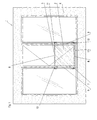
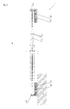
- a device 1 is shown by the two, firmly bonded together by a film 3, glass plate 2 are supported as parapet railing 5 on a floor 7 and on a building facade 4.
- the two interconnected by the film 3 glass plates 2 thus form a safety glass composite, which prevents complete breakage of the glass plate 2 even in glass breakage and consequently the building facade 6 and the balustrade 5 are not destroyed in a corresponding case of damage.
- the railing parapet 5 is to be provided on an inwardly opening door to form a fall protection.
- the balustrade parapet 5 is designed to be transparent, that is to say in the form of double-walled or multi-walled glass plates 2. In this case, the glass plates 2 fixing holding elements should affect the visual impression as little as possible.
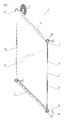
- the two glass plates 2 are provided at its upper end face 8 and at its lower end face 8 'with a profiled rail 11 which is made of metal.
- the glass plates 2 are connected by means of a thermosetting liquid adhesive 10 positively to the respective rail 11 and that over the entire length of the end face 8 and 8 '.
- fastening bolts 12 are formed on the outer wall, which are supported on the building facade 4 via screws 15. Consequently, the two glass plates 2 are held exclusively on the hardened liquid adhesive 10 and the two rails 11 on the facade 4; additional holes that are to be incorporated into the glass plates 2, therefore, are not provided to support them on the facade 4.
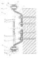
- FIG. 3 the formation of a building facade 4 consisting of the glass plates 2 is shown.
- the required for supporting rail 11 ' has an inner wall 20 which is configured in its cross section for receiving the glass plate 2 and the liquid adhesive 10 U-shaped, and an outer wall 21, between which a cavity 16 is formed.
- the rail 11 ' is produced by extrusion.
- the two profiled rails 11 ' project beyond the lateral vertical end faces 9 and 9', whereby a mounting region 14 is formed, which can be used to insert into the cavity 16 of the profiled rail 11 'a fastening bolt 12 which passes through the inner wall 20 and firmly connected to this.
- a holding plate 13 can be attached, which is fixed via the fastening bolt 12 fixed to the rail 11' and which is locked via one or more screws 15 on the facade 6.
- the outer contour of the outer wall 21 is designed in this embodiment, for aesthetic reasons, circular or arcuate in order to create a flowing shape.
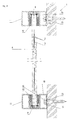
- FIG. 4 is the rail 11 'designed such that the cavity 16 is rectangular in cross-section and the outer wall 21 is flat and therefore can be placed directly on the facade 6 to the respective rail 11' by means of screws 15 directly to the facade. 5 connect to.
- the fastening bolts 12 and the screws 15, which are arranged in the cavity 16 of the rail 11 ', are accessible from the outside, because of the cavity 16 of the rail 11 'is open at the side, so that the arranged in this screw 15 or mounting bolts 12 can be achieved.
- the profile rails 11 can also be designed such that laterally next to the U-shaped cross section of the rail 11" a laterally projecting web 17 may be formed, which will be used as an assembly area 14 for certain installation situations.
- the webs 17 are perpendicular to the surfaces of the glass plates 2 and can be placed directly on the floor 7 and the facade 6.
- the profile rails 11 are thus supported by the screws 15, which extend in the region of the web 17 and pass through this, on the bottom 7 and the facade 6.
- FIG. 6 is an L-shaped rail 11 '''shown, which projects beyond the two laterally extending vertical end faces 9 and 9' of the glass plates 2.
- the projecting portion of the L-shaped rail 11 "' is used as a mounting portion 14 and placed directly on the facade 6 or the bottom 7 to be connected by means of screws 15 with these can.
Landscapes
- Engineering & Computer Science (AREA)
- Architecture (AREA)
- Civil Engineering (AREA)
- Structural Engineering (AREA)
- Load-Bearing And Curtain Walls (AREA)
- Escalators And Moving Walkways (AREA)
Applications Claiming Priority (1)
| Application Number | Priority Date | Filing Date | Title |
|---|---|---|---|
| DE102008017527A DE102008017527A1 (de) | 2008-04-03 | 2008-04-03 | Vorrichtung zur Abstützung von mindestens einer Glasplatte |
Publications (2)
| Publication Number | Publication Date |
|---|---|
| EP2107183A2 true EP2107183A2 (fr) | 2009-10-07 |
| EP2107183A3 EP2107183A3 (fr) | 2012-02-08 |
Family
ID=40459896
Family Applications (1)
| Application Number | Title | Priority Date | Filing Date |
|---|---|---|---|
| EP09003581A Withdrawn EP2107183A3 (fr) | 2008-04-03 | 2009-03-12 | Dispositif pour supporter au moins un panneau de verre |
Country Status (2)
| Country | Link |
|---|---|
| EP (1) | EP2107183A3 (fr) |
| DE (1) | DE102008017527A1 (fr) |
Citations (4)
| Publication number | Priority date | Publication date | Assignee | Title |
|---|---|---|---|---|
| DE8616851U1 (de) | 1986-06-25 | 1987-02-19 | Gerhardi & Cie, 5880 Lüdenscheid | Geländerbrüstung |
| AT403504B (de) | 1996-07-17 | 1998-03-25 | Feigl Bernhard | Bei- und unterlagsteil zur aufnahme eines schaftförmigen verbinders |
| CA2200265A1 (fr) | 1997-03-18 | 1998-09-18 | Domenico Murdaca | Ensemble de rampe |
| DE202005015131U1 (de) | 2005-09-24 | 2007-02-15 | Schneider, Frank, Dipl.-Ing. (FH) | Glaslagerung |
Family Cites Families (3)
| Publication number | Priority date | Publication date | Assignee | Title |
|---|---|---|---|---|
| US4690383A (en) * | 1986-04-04 | 1987-09-01 | Craneveyor Corp. | Panel rail system |
| DE29718854U1 (de) * | 1997-10-23 | 1998-01-02 | Sks Stakusit Kunststoff Gmbh | Profilrahmen, insbesondere U-Profilrahmen zur Halterung von Flächenelementen wie Glasscheiben, Kunststoffplatten o.dgl. |
| US8944414B2 (en) * | 2005-06-16 | 2015-02-03 | C.R. Laurence Company, Inc. | Component railing system and method of installation |
-
2008
- 2008-04-03 DE DE102008017527A patent/DE102008017527A1/de not_active Ceased
-
2009
- 2009-03-12 EP EP09003581A patent/EP2107183A3/fr not_active Withdrawn
Patent Citations (4)
| Publication number | Priority date | Publication date | Assignee | Title |
|---|---|---|---|---|
| DE8616851U1 (de) | 1986-06-25 | 1987-02-19 | Gerhardi & Cie, 5880 Lüdenscheid | Geländerbrüstung |
| AT403504B (de) | 1996-07-17 | 1998-03-25 | Feigl Bernhard | Bei- und unterlagsteil zur aufnahme eines schaftförmigen verbinders |
| CA2200265A1 (fr) | 1997-03-18 | 1998-09-18 | Domenico Murdaca | Ensemble de rampe |
| DE202005015131U1 (de) | 2005-09-24 | 2007-02-15 | Schneider, Frank, Dipl.-Ing. (FH) | Glaslagerung |
Also Published As
| Publication number | Publication date |
|---|---|
| EP2107183A3 (fr) | 2012-02-08 |
| DE102008017527A1 (de) | 2009-10-08 |
Similar Documents
| Publication | Publication Date | Title |
|---|---|---|
| EP2194207B1 (fr) | Dispositif de support du panneau en verre d'un garde-corps | |
| EP2365155A1 (fr) | Dispositif de fixation d'un appui de balustrade | |
| EP1496550A2 (fr) | Système de montage pour des modules de photovoltaique | |
| WO2021175708A1 (fr) | Dispositif de protection lors de travaux d'installation sur un escalier roulant ou un trottoir roulant | |
| EP2112296B1 (fr) | Paroi de protection ou élément de pression destiné au support d'une paroi de protection | |
| EP1697124A1 (fr) | Vitrage composite | |
| DE29607069U1 (de) | Isolierglasscheibe mit fotovoltaischem Element | |
| EP1840314B1 (fr) | Composant coupe-feu | |
| EP1830012B1 (fr) | Dispositif de support pour un panneau | |
| DE202018106077U1 (de) | Glasträgerkonstruktion und Rahmenkonstruktion | |
| DE202007002745U1 (de) | Vorrichtung zur Abstützung einer Geländerbrüstung | |
| EP2107183A2 (fr) | Dispositif pour supporter au moins un panneau de verre | |
| EP3453807A1 (fr) | Dispositif de fixation pour éléments structurels en forme de plaque, en particulier éléments de façade | |
| DE4000969A1 (de) | Anordnung zum befestigen einer gebaeudeplatte an einer gebaeudewand | |
| DE102012102243A1 (de) | Rahmenbausatz, Solarmodulvorrichtung und Solarmodul-Montageverfahren | |
| DE10138894A1 (de) | Natursteinverbundplatte | |
| EP1826331A2 (fr) | Aide au montage et construction de poteau traverse | |
| DE4140867A1 (de) | Fassadenkonstruktion | |
| DE102021129115A1 (de) | Geländer mit einer Vorrichtung zum Verschließen eines freien Raums | |
| DE10032985A1 (de) | Befestigungssystem für Fassadenverkleidungen | |
| DE2707718A1 (de) | Aus platten zusammengesetzte unterdecke | |
| EP3085873B1 (fr) | Panneau a effet | |
| EP3686368B1 (fr) | Garde-corps | |
| DE102023000441B4 (de) | Geländersystem mit Geländerplatten | |
| DE29807619U1 (de) | Glas-Bauwerk |
Legal Events
| Date | Code | Title | Description |
|---|---|---|---|
| PUAI | Public reference made under article 153(3) epc to a published international application that has entered the european phase |
Free format text: ORIGINAL CODE: 0009012 |
|
| AK | Designated contracting states |
Kind code of ref document: A2 Designated state(s): AT BE BG CH CY CZ DE DK EE ES FI FR GB GR HR HU IE IS IT LI LT LU LV MC MK MT NL NO PL PT RO SE SI SK TR |
|
| AX | Request for extension of the european patent |
Extension state: AL BA RS |
|
| PUAL | Search report despatched |
Free format text: ORIGINAL CODE: 0009013 |
|
| AK | Designated contracting states |
Kind code of ref document: A3 Designated state(s): AT BE BG CH CY CZ DE DK EE ES FI FR GB GR HR HU IE IS IT LI LT LU LV MC MK MT NL NO PL PT RO SE SI SK TR |
|
| AX | Request for extension of the european patent |
Extension state: AL BA RS |
|
| RIC1 | Information provided on ipc code assigned before grant |
Ipc: E04F 11/18 20060101ALI20120102BHEP Ipc: E04F 13/14 20060101ALI20120102BHEP Ipc: E04F 13/08 20060101AFI20120102BHEP |
|
| 17P | Request for examination filed |
Effective date: 20120418 |
|
| AKX | Designation fees paid |
Designated state(s): AT BE BG CH CY CZ DE DK EE ES FI FR GB GR HR HU IE IS IT LI LT LU LV MC MK MT NL NO PL PT RO SE SI SK TR |
|
| 17Q | First examination report despatched |
Effective date: 20150107 |
|
| STAA | Information on the status of an ep patent application or granted ep patent |
Free format text: STATUS: THE APPLICATION IS DEEMED TO BE WITHDRAWN |
|
| 18D | Application deemed to be withdrawn |
Effective date: 20181117 |