EP2107222A1 - Procédé d'accentuation de la part de dioxyde d'azote dans les gaz d'échappement - Google Patents
Procédé d'accentuation de la part de dioxyde d'azote dans les gaz d'échappement Download PDFInfo
- Publication number
- EP2107222A1 EP2107222A1 EP08016601A EP08016601A EP2107222A1 EP 2107222 A1 EP2107222 A1 EP 2107222A1 EP 08016601 A EP08016601 A EP 08016601A EP 08016601 A EP08016601 A EP 08016601A EP 2107222 A1 EP2107222 A1 EP 2107222A1
- Authority
- EP
- European Patent Office
- Prior art keywords
- exhaust gas
- partial
- ammonia
- catalyst
- downstream
- Prior art date
- Legal status (The legal status is an assumption and is not a legal conclusion. Google has not performed a legal analysis and makes no representation as to the accuracy of the status listed.)
- Granted
Links
Images

Classifications
-
- F—MECHANICAL ENGINEERING; LIGHTING; HEATING; WEAPONS; BLASTING
- F01—MACHINES OR ENGINES IN GENERAL; ENGINE PLANTS IN GENERAL; STEAM ENGINES
- F01N—GAS-FLOW SILENCERS OR EXHAUST APPARATUS FOR MACHINES OR ENGINES IN GENERAL; GAS-FLOW SILENCERS OR EXHAUST APPARATUS FOR INTERNAL-COMBUSTION ENGINES
- F01N3/00—Exhaust or silencing apparatus having means for purifying, rendering innocuous, or otherwise treating exhaust
- F01N3/08—Exhaust or silencing apparatus having means for purifying, rendering innocuous, or otherwise treating exhaust for rendering innocuous
- F01N3/10—Exhaust or silencing apparatus having means for purifying, rendering innocuous, or otherwise treating exhaust for rendering innocuous by thermal or catalytic conversion of noxious components of exhaust
- F01N3/18—Exhaust or silencing apparatus having means for purifying, rendering innocuous, or otherwise treating exhaust for rendering innocuous by thermal or catalytic conversion of noxious components of exhaust characterised by methods of operation; Control
- F01N3/20—Exhaust or silencing apparatus having means for purifying, rendering innocuous, or otherwise treating exhaust for rendering innocuous by thermal or catalytic conversion of noxious components of exhaust characterised by methods of operation; Control specially adapted for catalytic conversion
- F01N3/206—Adding periodically or continuously substances to exhaust gases for promoting purification, e.g. catalytic material in liquid form, NOx reducing agents
- F01N3/2066—Selective catalytic reduction [SCR]
-
- F—MECHANICAL ENGINEERING; LIGHTING; HEATING; WEAPONS; BLASTING
- F01—MACHINES OR ENGINES IN GENERAL; ENGINE PLANTS IN GENERAL; STEAM ENGINES
- F01N—GAS-FLOW SILENCERS OR EXHAUST APPARATUS FOR MACHINES OR ENGINES IN GENERAL; GAS-FLOW SILENCERS OR EXHAUST APPARATUS FOR INTERNAL-COMBUSTION ENGINES
- F01N13/00—Exhaust or silencing apparatus characterised by constructional features
- F01N13/011—Exhaust or silencing apparatus characterised by constructional features having two or more purifying devices arranged in parallel
-
- F—MECHANICAL ENGINEERING; LIGHTING; HEATING; WEAPONS; BLASTING
- F01—MACHINES OR ENGINES IN GENERAL; ENGINE PLANTS IN GENERAL; STEAM ENGINES
- F01N—GAS-FLOW SILENCERS OR EXHAUST APPARATUS FOR MACHINES OR ENGINES IN GENERAL; GAS-FLOW SILENCERS OR EXHAUST APPARATUS FOR INTERNAL-COMBUSTION ENGINES
- F01N3/00—Exhaust or silencing apparatus having means for purifying, rendering innocuous, or otherwise treating exhaust
- F01N3/02—Exhaust or silencing apparatus having means for purifying, rendering innocuous, or otherwise treating exhaust for cooling, or for removing solid constituents of, exhaust
- F01N3/021—Exhaust or silencing apparatus having means for purifying, rendering innocuous, or otherwise treating exhaust for cooling, or for removing solid constituents of, exhaust by means of filters
- F01N3/023—Exhaust or silencing apparatus having means for purifying, rendering innocuous, or otherwise treating exhaust for cooling, or for removing solid constituents of, exhaust by means of filters using means for regenerating the filters, e.g. by burning trapped particles
- F01N3/0231—Exhaust or silencing apparatus having means for purifying, rendering innocuous, or otherwise treating exhaust for cooling, or for removing solid constituents of, exhaust by means of filters using means for regenerating the filters, e.g. by burning trapped particles using special exhaust apparatus upstream of the filter for producing nitrogen dioxide, e.g. for continuous filter regeneration systems [CRT]
-
- F—MECHANICAL ENGINEERING; LIGHTING; HEATING; WEAPONS; BLASTING
- F01—MACHINES OR ENGINES IN GENERAL; ENGINE PLANTS IN GENERAL; STEAM ENGINES
- F01N—GAS-FLOW SILENCERS OR EXHAUST APPARATUS FOR MACHINES OR ENGINES IN GENERAL; GAS-FLOW SILENCERS OR EXHAUST APPARATUS FOR INTERNAL-COMBUSTION ENGINES
- F01N3/00—Exhaust or silencing apparatus having means for purifying, rendering innocuous, or otherwise treating exhaust
- F01N3/02—Exhaust or silencing apparatus having means for purifying, rendering innocuous, or otherwise treating exhaust for cooling, or for removing solid constituents of, exhaust
- F01N3/021—Exhaust or silencing apparatus having means for purifying, rendering innocuous, or otherwise treating exhaust for cooling, or for removing solid constituents of, exhaust by means of filters
- F01N3/031—Exhaust or silencing apparatus having means for purifying, rendering innocuous, or otherwise treating exhaust for cooling, or for removing solid constituents of, exhaust by means of filters having means for by-passing filters, e.g. when clogged or during cold engine start
-
- F—MECHANICAL ENGINEERING; LIGHTING; HEATING; WEAPONS; BLASTING
- F01—MACHINES OR ENGINES IN GENERAL; ENGINE PLANTS IN GENERAL; STEAM ENGINES
- F01N—GAS-FLOW SILENCERS OR EXHAUST APPARATUS FOR MACHINES OR ENGINES IN GENERAL; GAS-FLOW SILENCERS OR EXHAUST APPARATUS FOR INTERNAL-COMBUSTION ENGINES
- F01N3/00—Exhaust or silencing apparatus having means for purifying, rendering innocuous, or otherwise treating exhaust
- F01N3/08—Exhaust or silencing apparatus having means for purifying, rendering innocuous, or otherwise treating exhaust for rendering innocuous
- F01N3/0807—Exhaust or silencing apparatus having means for purifying, rendering innocuous, or otherwise treating exhaust for rendering innocuous by using absorbents or adsorbents
- F01N3/0821—Exhaust or silencing apparatus having means for purifying, rendering innocuous, or otherwise treating exhaust for rendering innocuous by using absorbents or adsorbents combined with particulate filter
-
- F—MECHANICAL ENGINEERING; LIGHTING; HEATING; WEAPONS; BLASTING
- F02—COMBUSTION ENGINES; HOT-GAS OR COMBUSTION-PRODUCT ENGINE PLANTS
- F02B—INTERNAL-COMBUSTION PISTON ENGINES; COMBUSTION ENGINES IN GENERAL
- F02B37/00—Engines characterised by provision of pumps driven at least for part of the time by exhaust
- F02B37/12—Control of the pumps
- F02B37/18—Control of the pumps by bypassing exhaust from the inlet to the outlet of turbine or to the atmosphere
-
- F—MECHANICAL ENGINEERING; LIGHTING; HEATING; WEAPONS; BLASTING
- F01—MACHINES OR ENGINES IN GENERAL; ENGINE PLANTS IN GENERAL; STEAM ENGINES
- F01N—GAS-FLOW SILENCERS OR EXHAUST APPARATUS FOR MACHINES OR ENGINES IN GENERAL; GAS-FLOW SILENCERS OR EXHAUST APPARATUS FOR INTERNAL-COMBUSTION ENGINES
- F01N2240/00—Combination or association of two or more different exhaust treating devices, or of at least one such device with an auxiliary device, not covered by indexing codes F01N2230/00 or F01N2250/00, one of the devices being
- F01N2240/40—Combination or association of two or more different exhaust treating devices, or of at least one such device with an auxiliary device, not covered by indexing codes F01N2230/00 or F01N2250/00, one of the devices being a hydrolysis catalyst
-
- F—MECHANICAL ENGINEERING; LIGHTING; HEATING; WEAPONS; BLASTING
- F01—MACHINES OR ENGINES IN GENERAL; ENGINE PLANTS IN GENERAL; STEAM ENGINES
- F01N—GAS-FLOW SILENCERS OR EXHAUST APPARATUS FOR MACHINES OR ENGINES IN GENERAL; GAS-FLOW SILENCERS OR EXHAUST APPARATUS FOR INTERNAL-COMBUSTION ENGINES
- F01N2410/00—By-passing, at least partially, exhaust from inlet to outlet of apparatus, to atmosphere or to other device
-
- F—MECHANICAL ENGINEERING; LIGHTING; HEATING; WEAPONS; BLASTING
- F01—MACHINES OR ENGINES IN GENERAL; ENGINE PLANTS IN GENERAL; STEAM ENGINES
- F01N—GAS-FLOW SILENCERS OR EXHAUST APPARATUS FOR MACHINES OR ENGINES IN GENERAL; GAS-FLOW SILENCERS OR EXHAUST APPARATUS FOR INTERNAL-COMBUSTION ENGINES
- F01N2610/00—Adding substances to exhaust gases
- F01N2610/02—Adding substances to exhaust gases the substance being ammonia or urea
-
- Y—GENERAL TAGGING OF NEW TECHNOLOGICAL DEVELOPMENTS; GENERAL TAGGING OF CROSS-SECTIONAL TECHNOLOGIES SPANNING OVER SEVERAL SECTIONS OF THE IPC; TECHNICAL SUBJECTS COVERED BY FORMER USPC CROSS-REFERENCE ART COLLECTIONS [XRACs] AND DIGESTS
- Y02—TECHNOLOGIES OR APPLICATIONS FOR MITIGATION OR ADAPTATION AGAINST CLIMATE CHANGE
- Y02T—CLIMATE CHANGE MITIGATION TECHNOLOGIES RELATED TO TRANSPORTATION
- Y02T10/00—Road transport of goods or passengers
- Y02T10/10—Internal combustion engine [ICE] based vehicles
- Y02T10/12—Improving ICE efficiencies
Definitions
- the invention relates to a method for increasing the nitrogen dioxide content in the exhaust gas of an internal combustion engine upstream of an SCR system for the selective catalytic reduction of nitrogen oxides with the aid of ammonia and / or ammonia-releasing reducing agents.
- nitrogen oxides are among the limited exhaust gas components that arise during combustion processes and whose permissible emissions are being lowered even further.
- different methods are used today.
- the reduction of nitrogen oxides is usually done with the aid of catalysts, in oxygen-rich exhaust gas, a reducing agent is also required in order to increase the selectivity and NO x conversions.
- SCR method where SCR stands for "selective catalytic reduction". They have been used for many years in power plants and, more recently, in internal combustion engines. A detailed description of such methods is the DE 34 28 232 A1 refer to.
- V 2 O 5 -containing mixed oxides for example in the form V 2 O 5 / WO 3 / TiO 2 , are used become. Typical V 2 O 5 contents are between 0.2-3%.
- reducing agents ammonia or ammonia releasing compounds, such as urea or ammonium formate, in solid or solution form are used in practical application. The decomposition of these substances and thus the release of ammonia is crucial in the SCR process for the applicability of the process. (NH 2 ) 2 CO + H 2 O ⁇ 2NH 3 + CO 2 (1)
- hydrolysis or urea decomposition catalysts (EP0487886B1 and EP0555746B1 ), in which the decomposition temperatures can be lowered to about 170 ° C. They accelerate the hydrolysis of isocyanic acid released by thermolysis during urea decomposition to NH 3 and CO 2 .
- the hydrolysis catalysts are often operated in a partial exhaust stream taken from the main stream ( EP1052009B1 ). It is particularly advantageous to remove the exhaust gas partial stream as close to the engine as possible in order to be able to operate the hydrolysis catalytic converter at a high temperature level.
- V 2 O 5 As SCR active component is critical. The reason for this lies in the low thermal stability of these catalysts. At an exhaust gas temperature of over 650 ° C, sublimation of V 2 O 5 occurs .
- V 2 O 5 -free, transition metal-containing, in particular iron-, cobalt- or copper-containing, catalysts are used. In this context, it has proven particularly advantageous to integrate these transition metals into zeolites by ion exchange ( DE 3 912 596 C2 ). Due to the very large surface area of the zeolites, this allows a considerable increase in the active surface area and thus a significant increase in the achievable turnover.
- the process according to the invention advantageously makes it possible to reduce the catalyst volume required for the NO oxidation and the amount of precious metal used.
- the object is achieved by a method according to the characterizing part of claim 1, advantageous developments of the method according to the invention are characterized in the dependent claims.
- the basic idea of the invention is to increase the NO 2 content by reducing the NO concentration on the one hand and increasing the residence time in the NO oxidation catalyst (s) on the other hand.
- the exhaust gas stream upstream of a main SCR catalytic converter is divided into at least two partial exhaust gas streams.
- At least one NO oxidation catalyst for forming NO 2 from engine-generated NO is provided in the first partial exhaust gas stream. Due to the division into, for example, two partial exhaust gas streams, the volume flow drops via this NO oxidation catalyst, which results in an increase in the residence time. This leads to an increase in the amounts of NO 2 formed on the NO oxidation catalyst.
- a partial flow SCR catalytic converter is integrated in the second partial exhaust gas flow. Upstream of this partial flow SCR catalyst is added ammonia and / or ammonia releasing reducing agent. This leads to a reduction of the nitrogen oxides emitted by the engine, in particular of the nitrogen monoxide which is mainly present. Subsequently, the two partial exhaust gas streams are recombined and the exhaust gas stream is then passed through the downstream aftertreatment systems, in particular a main SCR catalytic converter and / or a NO x storage catalytic converter and / or particle filter and / or particle separator.
- the volume of the NO oxidation catalyst was equal to 5 liters compared to the prior art, the SCR volume of 2.5 liters being 50% of the NO oxidation volume.
- the NO x and NO concentration before the catalysts is 1000 ppm.
- oxidation of the NO to the oxidation catalyst is obtained downstream of this a NO 2 concentration of 300ppm for the prior art, by the inventive method, on the other hand, due to the higher residence time, on the other hand, a NO 2 concentration of 500 ppm.
- the SCR catalytic converter arranged in the second partial exhaust gas flow it is possible to reduce the NO concentration in this exhaust gas branch to 50 ppm.
- the table below shows the conditions when the residence time in the NO oxidation catalyst of the process according to the invention is identical to that of the prior art.
- the volume of NO oxidation catalysts is halved, so it is only 2.5 liters. This results in the downstream of the two oxidation catalysts identical NO 2 concentrations.
- By lowering the NO concentration in the process according to the invention almost identical NO contents of 30% and 29%, respectively, result after the two systems.
- the partial flow SCR catalyst and the main SCR catalyst are operated at different temperature and NO 2 levels, different catalyst types are advantageously used.
- different catalyst types are advantageously used.
- the partial flow SCR catalyst advantageously iron and / or copper and / or cobalt Zeolihte used, while for the main SCR catalyst as active components and vanadium and / or tungsten and / or titanium and / or their oxides are conceivable.
- ammonia-releasing substance in particular urea or urea solution
- the arrangement of a catalyst for the decomposition of the reducing agent between the feed point for the reducing agent and the partial flow SCR catalytic converter is expedient.
- active components for this decomposition catalyst are titanium and / or silicon and / or vanadium and / or tungsten and / or their oxides and / or zeolites in question.
- Platinum and / or its oxides and / or zeolites can advantageously be used as active materials for the NO oxidation catalyst arranged in the first partial exhaust stream.
- reducing agent In order to be able to display high NO x conversions on the main SCR catalyst, sufficiently high amounts of reducing agent are necessary. In the simplest case, this is realized via the metering unit arranged upstream of the partial flow SCR catalytic converter by metering in more reducing agent than is required on the partial flow SCR catalytic converter. As a result, the unreacted reducing agent passes through the partial flow SCR catalyst and reaches the main SCR catalysts, thus allowing NO x conversion.
- a second advantageous possibility is to provide a second, downstream of the partial flow SCR catalyst, metering device for the reducing agent. This offers the advantage that the amount of reducing agent flowing over the partial flow SCR catalyst can be varied, which in turn makes the NO 2 contents free and independent of Set the NO x conversions on the main SCR catalytic converter.
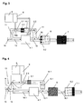
- Fig. 1 schematically shown, a prior art arrangement shown, are removed with the nitrogen oxides by way of selective catalytic reduction of the exhaust gas of an internal combustion engine.
- a reducing agent is added as close to the engine as possible to the hot exhaust gas.
- the reducing agent as is the case in motor vehicles with SCR catalyst in practice, is an aqueous urea solution, but of course the addition of urea in solid form is also conceivable, as already described in detail in the relevant specialist literature. It is also possible to add ammonia as a reducing agent, which is obtained elsewhere, for example under more favorable thermal conditions, from a substance which releases ammonia.
- the metering takes place as a function of operating parameters of the internal combustion engine, controlled by a motor control unit (not represented), in such a way that via a nozzle 2, the aqueous urea solution is sprayed immediately before a hydrolysis catalyst 3 in the partial exhaust gas stream.
- the task of the hydrolysis catalyst 3 is to convert the aqueous urea solution as completely as possible into ammonia and water vapor while avoiding by-products. Under certain conditions, this splitting takes place sufficiently without hydrolysis catalyst, so that it can then be omitted.
- a NO oxidation catalyst 4 is arranged in the quantitatively larger partial exhaust gas stream whose task is to oxidize as much of the nitrogen monoxide contained in the exhaust gas by means of the excess oxygen present in the exhaust gas to nitrogen dioxide according to the reaction described above with (5) ,
- the partial exhaust gas streams are brought together again downstream of the hydrolysis catalytic converter and NO oxidation catalytic converter.
- the actual selective catalytic reduction of the nitrogen oxides takes place in the downstream of the hydrolysis 3 and NO oxidation catalyst located main SCR catalyst 6, the largest possible proportion of nitrogen oxides present in the exhaust gas (NO x ) while high selectivity of reduction in nitrogen and water vapor transferred without excess ammonia (NH 3 ) remains in the exhaust stream.
- NO x the largest possible proportion of nitrogen oxides present in the exhaust gas
- NH 3 ammonia
- the nitrogen dioxide present in the exhaust gas stream is more reactive than the nitrogen monoxide contained in the exhaust gas, it is therefore desirable to design the NO oxidation catalyst 4 such that the highest possible proportion of nitrogen monoxide is converted into nitrogen dioxide.
- the hydrolysis catalytic converter 3 can be dispensed with.
- FIG. 2 An exemplary embodiment of the exhaust aftertreatment system according to the invention is in Fig. 2 shown.
- the arrangement shows a division of the coming of an internal combustion engine (not shown) exhaust gas flow 16 into a first partial exhaust gas stream 10 and a second partial exhaust gas stream 11, wherein both partial exhaust gas streams can be chosen quantitatively equal in size.
- the reducing agent in this example, aqueous urea solution, also known under the trade name AdBlue
- AdBlue aqueous urea solution
- the metering takes place by means of a metering device 9 which is controlled as a function of operating parameters of the internal combustion engine and extracts the aqueous urea solution from a storage container 8 and injects it into the exhaust gas flow in predetermined amounts via a nozzle 2.1, depending on the operating state of the internal combustion engine.
- a partial flow SCR catalytic converter 6.1 is arranged in the second partial exhaust gas flow 11, which, as already explained above, greatly lowers the NO concentration in the second partial exhaust gas flow 11.
- a NO oxidation catalyst 4.1 is arranged parallel to the partial flow SCR catalytic converter 6.1. It serves to increase the proportion of nitrogen dioxide in the exhaust gas stream 11, as already stated above.
- Fig. 3 is an arrangement similar to that in connection with the FIG. 2 described, shown. It is only for the decomposition of the reducing agent additionally in the partial flow 11 and upstream of the partial flow SCR catalyst 6.1, a decomposition or hydrolysis 3.1 mounted, which promotes the release of ammonia from the reducing agent.
- the metering of the aqueous urea solution by means of the nozzle 2.1 is carried out in this example so that the added amount is sufficiently dimensioned only for the reaction taking place in the partial flow SCR catalyst 6.1.
- the supply of the amount of aqueous urea solution necessary for the selective catalytic reduction in the mainstream SCR catalytic converter 6 takes place via a second nozzle 2.2, which is arranged downstream of the partial flow SCR catalytic converter in the second partial exhaust gas stream 11.
- a second nozzle 2.2 which is arranged downstream of the partial flow SCR catalytic converter in the second partial exhaust gas stream 11.
- the Exhaust gas added reducing agent in ammonia is the main CSR catalyst 6 upstream of another hydrolysis 3.2. This can be achieved, for example, by coating the main SCR catalyst on its input side with a catalyst material favoring hydrolysis.
- At least one single-stage turbocharger arrangement is often present, which compresses the exhaust air supplied to the internal combustion engine with the aid of the exhaust gas enthalpy contained in the exhaust gas stream.
- this raises problems because the exhaust gas flowing through the turbines of the exhaust gas turbocharger or exhaust gas is inevitably strongly cooled by it.
- Such a cooled exhaust gas flow is not able to achieve sufficient exhaust gas temperatures for the SCR reaction in the partial exhaust gas stream, especially during start-up operation and in the lower part-load range. Even if hydrolysis catalysts are used, the temperature level is usually insufficient. Remedy for this problem, the arrangement creates Fig.
- the exhaust gas flow coming from the internal combustion engine branches in front of the turbine 14 of the exhaust gas turbocharger 13 in such a way that a second partial exhaust gas stream 11.1 is withdrawn therefrom, while the first partial exhaust gas stream 10.1 is passed over the turbine 14 via this drives the compressor 15 and leaves the turbocharger.
- the hydrolysis of the reducing agent takes place in this example in the partial exhaust stream 11.1, this is supplied with a metering consisting of reservoir 8, metering device 9 and nozzle 2.1, the reducing agent in dependence on operating parameters of the internal combustion engine in the second partial exhaust stream 11.1.
- the second Exhaust partial stream 11.1 prevailing relatively high exhaust gas temperature and the feed point downstream of the hydrolysis 3.1, the reducing agent without the onset of problematic reaction products, such as cyanuric acid, split off ammonia.
- the exhaust gas then flows through the partial flow SCR catalytic converter 6.1 arranged in the partial exhaust gas stream 11.1, before it again meets the first partial exhaust gas stream 10.1, which has been guided via the exhaust gas turbocharger 13 3.
- the nitrogen oxide content of the exhaust gas which is mainly nitrogen monoxide, is greatly reduced by the selective catalytic reduction taking place.
- first partial exhaust gas flow is guided 10.1 via a NO 2 oxidation catalyst 4.1, the, just as in the previous examples, contained in the first partial exhaust gas stream 10.1 nitric oxide is oxidized to a certain percentage to nitrogen dioxide, examples of recoverable Nitrogen dioxide levels downstream of the NO 2 oxidation catalyst have been described above for particular configurations and are listed in Tables. Downstream of the NO 2 oxidation catalyst 4.1, the merging of the exhaust gas substreams 11.1 and 10.1 to the total exhaust gas stream 16.1 takes place.
- the nitrogen oxide lean exhaust gas coming from the second partial exhaust stream 11.1 and the exhaust gas enriched with nitrogen dioxide from the first exhaust gas stream 10.1 form, after the merging, an exhaust gas mixture with a greatly increased proportion of nitrogen dioxide compared to the procedure of the prior art.
- the exhaust gas with a greatly increased NO 2 content then flows through a particle separator / particle filter 5 arranged downstream of the return point, which on the one hand ensures thorough mixing and homogeneous distribution of the constituents contained in the exhaust gas and, on the other hand, accumulates soot particles from the exhaust gas which, with the aid of the oxidation catalyst 4.1 produced nitrogen dioxide are continuously converted to carbon monoxide, carbon dioxide, nitrogen and nitrogen monoxide.
- a particle separator / particle filter 5 arranged downstream of the return point, which on the one hand ensures thorough mixing and homogeneous distribution of the constituents contained in the exhaust gas and, on the other hand, accumulates soot particles from the exhaust gas which, with the aid of the oxidation catalyst 4.1 produced nitrogen dioxide are continuously converted to carbon monoxide, carbon dioxide, nitrogen and nitrogen monoxide.
- the particle separator is followed by a main SCR catalytic converter 6.2, which converts the nitrogen oxides present in the exhaust gas into nitrogen and water vapor by way of selective catalytic reduction.
- the SCR catalytic converter 6.1 is coated in its downstream region with an active material forming an NH 3 oxidation catalyst 7.1.
Landscapes
- Engineering & Computer Science (AREA)
- Chemical & Material Sciences (AREA)
- Combustion & Propulsion (AREA)
- Mechanical Engineering (AREA)
- General Engineering & Computer Science (AREA)
- Chemical Kinetics & Catalysis (AREA)
- Health & Medical Sciences (AREA)
- Toxicology (AREA)
- Exhaust Gas After Treatment (AREA)
Priority Applications (1)
| Application Number | Priority Date | Filing Date | Title |
|---|---|---|---|
| PL08016601T PL2107222T3 (pl) | 2008-04-04 | 2008-09-20 | Sposób zwiększania udziału ditlenku azotu w spalinach |
Applications Claiming Priority (1)
| Application Number | Priority Date | Filing Date | Title |
|---|---|---|---|
| DE102008017279A DE102008017279A1 (de) | 2008-04-04 | 2008-04-04 | Verfahren zur Anhebung des Stickstoffdioxidanteils im Abgas |
Publications (2)
| Publication Number | Publication Date |
|---|---|
| EP2107222A1 true EP2107222A1 (fr) | 2009-10-07 |
| EP2107222B1 EP2107222B1 (fr) | 2017-11-08 |
Family
ID=40873274
Family Applications (1)
| Application Number | Title | Priority Date | Filing Date |
|---|---|---|---|
| EP08016601.0A Active EP2107222B1 (fr) | 2008-04-04 | 2008-09-20 | Procédé d'accentuation de la part de dioxyde d'azote dans les gaz d'échappement |
Country Status (3)
| Country | Link |
|---|---|
| EP (1) | EP2107222B1 (fr) |
| DE (1) | DE102008017279A1 (fr) |
| PL (1) | PL2107222T3 (fr) |
Cited By (4)
| Publication number | Priority date | Publication date | Assignee | Title |
|---|---|---|---|---|
| US9261003B2 (en) | 2013-10-24 | 2016-02-16 | Bosal Emission Control Systems, N.V. | System and method for treating exhaust pipe |
| FR3028286A1 (fr) * | 2014-11-12 | 2016-05-13 | Peugeot Citroen Automobiles Sa | Dispositif de traitement des gaz d’echappement d’un vehicule automobile |
| EP3670855A1 (fr) * | 2018-12-19 | 2020-06-24 | Winterthur Gas & Diesel Ltd. | Système de post-traitement de gaz d'échappement |
| CN114667386A (zh) * | 2019-11-19 | 2022-06-24 | 斯堪尼亚商用车有限公司 | 用于诊断排气流中物质的氧化的方法和系统 |
Families Citing this family (2)
| Publication number | Priority date | Publication date | Assignee | Title |
|---|---|---|---|---|
| DE102012007890B4 (de) | 2012-04-23 | 2014-09-04 | Clariant Produkte (Deutschland) Gmbh | Abgasreinigungssystem zur Reinigung von Abgasströmen aus Dieselmotoren |
| EP3904650B1 (fr) | 2020-04-28 | 2023-10-04 | Liebherr-Components Colmar SAS | Système de post-traitement de gaz d'échappement |
Citations (1)
| Publication number | Priority date | Publication date | Assignee | Title |
|---|---|---|---|---|
| EP1892395A1 (fr) | 2006-08-16 | 2008-02-27 | MAN Nutzfahrzeuge AG | Système de traitement de gaz d'échappement |
Family Cites Families (12)
| Publication number | Priority date | Publication date | Assignee | Title |
|---|---|---|---|---|
| DE3428232A1 (de) | 1984-07-31 | 1986-02-06 | Süd-Chemie AG, 8000 München | Katalysator zur entfernung von stickoxiden aus abgasen |
| JPH0763631B2 (ja) | 1988-04-18 | 1995-07-12 | トヨタ自動車株式会社 | 排気ガス浄化用触媒の製造方法 |
| DE4038054A1 (de) | 1990-11-29 | 1992-06-04 | Man Technologie Gmbh | Verfahren und vorrichtung zur selektiven katalytischen no(pfeil abwaerts)x(pfeil abwaerts)-reduktion in sauerstoffhaltigen abgasen |
| EP0555746B1 (fr) | 1992-02-10 | 1997-09-10 | MAN Nutzfahrzeuge Aktiengesellschaft | Dispositif pour la réduction catalytique de NOx |
| GB9802504D0 (en) | 1998-02-06 | 1998-04-01 | Johnson Matthey Plc | Improvements in emission control |
| DE19855384A1 (de) | 1998-12-01 | 2000-06-08 | Bosch Gmbh Robert | Vorrichtung zum Nachbehandeln von Abgasen einer Brennkraftmaschine |
| JP2000225323A (ja) | 1999-02-04 | 2000-08-15 | Mazda Motor Corp | 排気ガス浄化用触媒 |
| DE19913462A1 (de) | 1999-03-25 | 2000-09-28 | Man Nutzfahrzeuge Ag | Verfahren zur thermischen Hydrolyse und Dosierung von Harnstoff bzw. wässriger Harnstofflösung in einem Reaktor |
| DE19960976C2 (de) | 1999-12-17 | 2002-01-24 | Karlsruhe Forschzent | Vorrichtung zur katalysierten Reduktion von Stickoxiden im Abgas einer Verbrennungsmaschine |
| US20020064956A1 (en) | 2000-11-29 | 2002-05-30 | King-Lung Wu | Method of forming a storage node of a capacitor |
| DE10206028A1 (de) | 2002-02-14 | 2003-08-28 | Man Nutzfahrzeuge Ag | Verfahren und Vorrichtung zur Erzeugung von Ammoniak |
| DE102006038289A1 (de) * | 2006-08-16 | 2008-02-21 | Man Nutzfahrzeuge Aktiengesellschaft | Abgasnachbehandlungssystem |
-
2008
- 2008-04-04 DE DE102008017279A patent/DE102008017279A1/de not_active Ceased
- 2008-09-20 PL PL08016601T patent/PL2107222T3/pl unknown
- 2008-09-20 EP EP08016601.0A patent/EP2107222B1/fr active Active
Patent Citations (1)
| Publication number | Priority date | Publication date | Assignee | Title |
|---|---|---|---|---|
| EP1892395A1 (fr) | 2006-08-16 | 2008-02-27 | MAN Nutzfahrzeuge AG | Système de traitement de gaz d'échappement |
Cited By (5)
| Publication number | Priority date | Publication date | Assignee | Title |
|---|---|---|---|---|
| US9261003B2 (en) | 2013-10-24 | 2016-02-16 | Bosal Emission Control Systems, N.V. | System and method for treating exhaust pipe |
| FR3028286A1 (fr) * | 2014-11-12 | 2016-05-13 | Peugeot Citroen Automobiles Sa | Dispositif de traitement des gaz d’echappement d’un vehicule automobile |
| EP3670855A1 (fr) * | 2018-12-19 | 2020-06-24 | Winterthur Gas & Diesel Ltd. | Système de post-traitement de gaz d'échappement |
| CN111335987A (zh) * | 2018-12-19 | 2020-06-26 | 温特图尔汽柴油公司 | 排气后处理系统 |
| CN114667386A (zh) * | 2019-11-19 | 2022-06-24 | 斯堪尼亚商用车有限公司 | 用于诊断排气流中物质的氧化的方法和系统 |
Also Published As
| Publication number | Publication date |
|---|---|
| PL2107222T3 (pl) | 2018-04-30 |
| DE102008017279A1 (de) | 2009-10-08 |
| EP2107222B1 (fr) | 2017-11-08 |
Similar Documents
| Publication | Publication Date | Title |
|---|---|---|
| EP1892395B1 (fr) | Système de traitement de gaz d'échappement | |
| EP1892394B1 (fr) | Système de traitement postérieur de gaz d'échappement | |
| EP1900916B1 (fr) | Système de traitement postérieur de gaz d'échappement | |
| EP2101049B1 (fr) | Système de post-traitement de gaz d'échappement compact | |
| EP1985819B1 (fr) | Système de traitement de gaz d'échappement | |
| EP1882832B1 (fr) | Dispositif destiné à réduire les oxydes d'azote dans des gaz d'échappement | |
| EP2907564B1 (fr) | Procédé de nettoyage de gaz d'échappement de moteurs diesel | |
| EP2568137B1 (fr) | Système d'injection chauffé pour systèmes de gaz d'échappement de moteurs diesel | |
| DE102014103678B4 (de) | Kompaktes abgasbehandlungssystem für einen dieselmotor | |
| DE102012006448B4 (de) | Verfahren zur Anwendung in Verbindung mit einer Abgasnachbehandlungsanlage | |
| EP1892396A1 (fr) | Système de traitement de gaz d'échappement | |
| EP1554474B1 (fr) | Installation d'epuration des gaz d'echappement d'un moteur a combustion interne et procede pour epurer ces gaz d'echappement | |
| EP2107222B1 (fr) | Procédé d'accentuation de la part de dioxyde d'azote dans les gaz d'échappement | |
| EP2597279B1 (fr) | Dispositif et procédé de nettoyage de gaz d'échappement de moteurs diesel | |
| DE202006020151U1 (de) | Katalysator | |
| DE102006031650B4 (de) | Anordnung zur Verminderung von Stickoxiden in Abgasen | |
| EP2811130A1 (fr) | Procédé et dispositif de désulfuration de reflux de gaz d'échappement | |
| EP1901833A1 (fr) | Procede de reduction de la teneur en particules et en oxydes d'azote d'un flux de gaz d'echappement d'un moteur a combustion interne et unite de traitement de gaz d'echappement correspondante | |
| EP2166207A1 (fr) | Dispositif et procédé de nettoyage d'un flux de gaz d'échappement d'un moteur à combustion interne, notamment d'un moteur à combustion interne capable de fonctionner en conditions pauvres | |
| EP2659950B1 (fr) | Système de traitement postérieur de gaz d'échappement | |
| DE202015104462U1 (de) | Abgasnachbehandlungssystem für einen Dieselmotor | |
| EP2166206B1 (fr) | Dispositif de dosage destiné au dosage d'un moyen de réduction, notamment pour une réduction catalytique sélective, dans un flux de gaz d'échappement d'un moteur à combustion interne | |
| DE102009014236B4 (de) | Vorrichtung zur Abgasreinigung für eine Brennkraftmaschine | |
| DE102015214734A1 (de) | Abgasnachbehandlungssystem für einen Dieselmotor | |
| DE102016207597A1 (de) | Abgasnachbehandlungssystem für einen Dieselmotor |
Legal Events
| Date | Code | Title | Description |
|---|---|---|---|
| PUAI | Public reference made under article 153(3) epc to a published international application that has entered the european phase |
Free format text: ORIGINAL CODE: 0009012 |
|
| 17P | Request for examination filed |
Effective date: 20090825 |
|
| AK | Designated contracting states |
Kind code of ref document: A1 Designated state(s): AT BE BG CH CY CZ DE DK EE ES FI FR GB GR HR HU IE IS IT LI LT LU LV MC MT NL NO PL PT RO SE SI SK TR |
|
| AX | Request for extension of the european patent |
Extension state: AL BA MK RS |
|
| AKX | Designation fees paid |
Designated state(s): AT BE BG CH CY CZ DE DK EE ES FI FR GB GR HR HU IE IS IT LI LT LU LV MC MT NL NO PL PT RO SE SI SK TR |
|
| RAP1 | Party data changed (applicant data changed or rights of an application transferred) |
Owner name: MAN TRUCK & BUS AG |
|
| RIN1 | Information on inventor provided before grant (corrected) |
Inventor name: DOERING, ANDREAS |
|
| 17Q | First examination report despatched |
Effective date: 20160429 |
|
| GRAP | Despatch of communication of intention to grant a patent |
Free format text: ORIGINAL CODE: EPIDOSNIGR1 |
|
| STAA | Information on the status of an ep patent application or granted ep patent |
Free format text: STATUS: GRANT OF PATENT IS INTENDED |
|
| INTG | Intention to grant announced |
Effective date: 20170811 |
|
| GRAS | Grant fee paid |
Free format text: ORIGINAL CODE: EPIDOSNIGR3 |
|
| GRAA | (expected) grant |
Free format text: ORIGINAL CODE: 0009210 |
|
| STAA | Information on the status of an ep patent application or granted ep patent |
Free format text: STATUS: THE PATENT HAS BEEN GRANTED |
|
| AK | Designated contracting states |
Kind code of ref document: B1 Designated state(s): AT BE BG CH CY CZ DE DK EE ES FI FR GB GR HR HU IE IS IT LI LT LU LV MC MT NL NO PL PT RO SE SI SK TR |
|
| REG | Reference to a national code |
Ref country code: GB Ref legal event code: FG4D Free format text: NOT ENGLISH |
|
| REG | Reference to a national code |
Ref country code: CH Ref legal event code: EP Ref country code: AT Ref legal event code: REF Ref document number: 944365 Country of ref document: AT Kind code of ref document: T Effective date: 20171115 |
|
| REG | Reference to a national code |
Ref country code: IE Ref legal event code: FG4D Free format text: LANGUAGE OF EP DOCUMENT: GERMAN |
|
| REG | Reference to a national code |
Ref country code: DE Ref legal event code: R096 Ref document number: 502008015709 Country of ref document: DE |
|
| REG | Reference to a national code |
Ref country code: SE Ref legal event code: TRGR |
|
| REG | Reference to a national code |
Ref country code: NL Ref legal event code: FP |
|
| REG | Reference to a national code |
Ref country code: LT Ref legal event code: MG4D |
|
| PG25 | Lapsed in a contracting state [announced via postgrant information from national office to epo] |
Ref country code: LT Free format text: LAPSE BECAUSE OF FAILURE TO SUBMIT A TRANSLATION OF THE DESCRIPTION OR TO PAY THE FEE WITHIN THE PRESCRIBED TIME-LIMIT Effective date: 20171108 Ref country code: ES Free format text: LAPSE BECAUSE OF FAILURE TO SUBMIT A TRANSLATION OF THE DESCRIPTION OR TO PAY THE FEE WITHIN THE PRESCRIBED TIME-LIMIT Effective date: 20171108 Ref country code: FI Free format text: LAPSE BECAUSE OF FAILURE TO SUBMIT A TRANSLATION OF THE DESCRIPTION OR TO PAY THE FEE WITHIN THE PRESCRIBED TIME-LIMIT Effective date: 20171108 Ref country code: NO Free format text: LAPSE BECAUSE OF FAILURE TO SUBMIT A TRANSLATION OF THE DESCRIPTION OR TO PAY THE FEE WITHIN THE PRESCRIBED TIME-LIMIT Effective date: 20180208 |
|
| PG25 | Lapsed in a contracting state [announced via postgrant information from national office to epo] |
Ref country code: GR Free format text: LAPSE BECAUSE OF FAILURE TO SUBMIT A TRANSLATION OF THE DESCRIPTION OR TO PAY THE FEE WITHIN THE PRESCRIBED TIME-LIMIT Effective date: 20180209 Ref country code: BG Free format text: LAPSE BECAUSE OF FAILURE TO SUBMIT A TRANSLATION OF THE DESCRIPTION OR TO PAY THE FEE WITHIN THE PRESCRIBED TIME-LIMIT Effective date: 20180208 Ref country code: HR Free format text: LAPSE BECAUSE OF FAILURE TO SUBMIT A TRANSLATION OF THE DESCRIPTION OR TO PAY THE FEE WITHIN THE PRESCRIBED TIME-LIMIT Effective date: 20171108 Ref country code: LV Free format text: LAPSE BECAUSE OF FAILURE TO SUBMIT A TRANSLATION OF THE DESCRIPTION OR TO PAY THE FEE WITHIN THE PRESCRIBED TIME-LIMIT Effective date: 20171108 Ref country code: IS Free format text: LAPSE BECAUSE OF FAILURE TO SUBMIT A TRANSLATION OF THE DESCRIPTION OR TO PAY THE FEE WITHIN THE PRESCRIBED TIME-LIMIT Effective date: 20180308 |
|
| PG25 | Lapsed in a contracting state [announced via postgrant information from national office to epo] |
Ref country code: CZ Free format text: LAPSE BECAUSE OF FAILURE TO SUBMIT A TRANSLATION OF THE DESCRIPTION OR TO PAY THE FEE WITHIN THE PRESCRIBED TIME-LIMIT Effective date: 20171108 Ref country code: EE Free format text: LAPSE BECAUSE OF FAILURE TO SUBMIT A TRANSLATION OF THE DESCRIPTION OR TO PAY THE FEE WITHIN THE PRESCRIBED TIME-LIMIT Effective date: 20171108 Ref country code: CY Free format text: LAPSE BECAUSE OF FAILURE TO SUBMIT A TRANSLATION OF THE DESCRIPTION OR TO PAY THE FEE WITHIN THE PRESCRIBED TIME-LIMIT Effective date: 20171108 Ref country code: DK Free format text: LAPSE BECAUSE OF FAILURE TO SUBMIT A TRANSLATION OF THE DESCRIPTION OR TO PAY THE FEE WITHIN THE PRESCRIBED TIME-LIMIT Effective date: 20171108 Ref country code: SK Free format text: LAPSE BECAUSE OF FAILURE TO SUBMIT A TRANSLATION OF THE DESCRIPTION OR TO PAY THE FEE WITHIN THE PRESCRIBED TIME-LIMIT Effective date: 20171108 |
|
| REG | Reference to a national code |
Ref country code: DE Ref legal event code: R097 Ref document number: 502008015709 Country of ref document: DE |
|
| PG25 | Lapsed in a contracting state [announced via postgrant information from national office to epo] |
Ref country code: RO Free format text: LAPSE BECAUSE OF FAILURE TO SUBMIT A TRANSLATION OF THE DESCRIPTION OR TO PAY THE FEE WITHIN THE PRESCRIBED TIME-LIMIT Effective date: 20171108 |
|
| PLBE | No opposition filed within time limit |
Free format text: ORIGINAL CODE: 0009261 |
|
| STAA | Information on the status of an ep patent application or granted ep patent |
Free format text: STATUS: NO OPPOSITION FILED WITHIN TIME LIMIT |
|
| PG25 | Lapsed in a contracting state [announced via postgrant information from national office to epo] |
Ref country code: MT Free format text: LAPSE BECAUSE OF FAILURE TO SUBMIT A TRANSLATION OF THE DESCRIPTION OR TO PAY THE FEE WITHIN THE PRESCRIBED TIME-LIMIT Effective date: 20171108 |
|
| REG | Reference to a national code |
Ref country code: FR Ref legal event code: PLFP Year of fee payment: 11 |
|
| 26N | No opposition filed |
Effective date: 20180809 |
|
| PG25 | Lapsed in a contracting state [announced via postgrant information from national office to epo] |
Ref country code: SI Free format text: LAPSE BECAUSE OF FAILURE TO SUBMIT A TRANSLATION OF THE DESCRIPTION OR TO PAY THE FEE WITHIN THE PRESCRIBED TIME-LIMIT Effective date: 20171108 |
|
| PG25 | Lapsed in a contracting state [announced via postgrant information from national office to epo] |
Ref country code: MC Free format text: LAPSE BECAUSE OF FAILURE TO SUBMIT A TRANSLATION OF THE DESCRIPTION OR TO PAY THE FEE WITHIN THE PRESCRIBED TIME-LIMIT Effective date: 20171108 |
|
| REG | Reference to a national code |
Ref country code: CH Ref legal event code: PL |
|
| REG | Reference to a national code |
Ref country code: BE Ref legal event code: MM Effective date: 20180930 |
|
| REG | Reference to a national code |
Ref country code: IE Ref legal event code: MM4A |
|
| PG25 | Lapsed in a contracting state [announced via postgrant information from national office to epo] |
Ref country code: LU Free format text: LAPSE BECAUSE OF NON-PAYMENT OF DUE FEES Effective date: 20180920 |
|
| PG25 | Lapsed in a contracting state [announced via postgrant information from national office to epo] |
Ref country code: IE Free format text: LAPSE BECAUSE OF NON-PAYMENT OF DUE FEES Effective date: 20180920 |
|
| PG25 | Lapsed in a contracting state [announced via postgrant information from national office to epo] |
Ref country code: CH Free format text: LAPSE BECAUSE OF NON-PAYMENT OF DUE FEES Effective date: 20180930 Ref country code: BE Free format text: LAPSE BECAUSE OF NON-PAYMENT OF DUE FEES Effective date: 20180930 Ref country code: LI Free format text: LAPSE BECAUSE OF NON-PAYMENT OF DUE FEES Effective date: 20180930 |
|
| REG | Reference to a national code |
Ref country code: DE Ref legal event code: R081 Ref document number: 502008015709 Country of ref document: DE Owner name: MAN TRUCK & BUS SE, DE Free format text: FORMER OWNER: MAN TRUCK & BUS AG, 80995 MUENCHEN, DE |
|
| REG | Reference to a national code |
Ref country code: AT Ref legal event code: MM01 Ref document number: 944365 Country of ref document: AT Kind code of ref document: T Effective date: 20180920 |
|
| PG25 | Lapsed in a contracting state [announced via postgrant information from national office to epo] |
Ref country code: AT Free format text: LAPSE BECAUSE OF NON-PAYMENT OF DUE FEES Effective date: 20180920 |
|
| PG25 | Lapsed in a contracting state [announced via postgrant information from national office to epo] |
Ref country code: TR Free format text: LAPSE BECAUSE OF FAILURE TO SUBMIT A TRANSLATION OF THE DESCRIPTION OR TO PAY THE FEE WITHIN THE PRESCRIBED TIME-LIMIT Effective date: 20171108 |
|
| PG25 | Lapsed in a contracting state [announced via postgrant information from national office to epo] |
Ref country code: PT Free format text: LAPSE BECAUSE OF FAILURE TO SUBMIT A TRANSLATION OF THE DESCRIPTION OR TO PAY THE FEE WITHIN THE PRESCRIBED TIME-LIMIT Effective date: 20171108 Ref country code: HU Free format text: LAPSE BECAUSE OF FAILURE TO SUBMIT A TRANSLATION OF THE DESCRIPTION OR TO PAY THE FEE WITHIN THE PRESCRIBED TIME-LIMIT; INVALID AB INITIO Effective date: 20080920 |
|
| PGFP | Annual fee paid to national office [announced via postgrant information from national office to epo] |
Ref country code: DE Payment date: 20250926 Year of fee payment: 18 |
|
| PGFP | Annual fee paid to national office [announced via postgrant information from national office to epo] |
Ref country code: PL Payment date: 20250910 Year of fee payment: 18 Ref country code: NL Payment date: 20250925 Year of fee payment: 18 Ref country code: IT Payment date: 20250922 Year of fee payment: 18 |
|
| PGFP | Annual fee paid to national office [announced via postgrant information from national office to epo] |
Ref country code: GB Payment date: 20250923 Year of fee payment: 18 |
|
| PGFP | Annual fee paid to national office [announced via postgrant information from national office to epo] |
Ref country code: FR Payment date: 20250925 Year of fee payment: 18 |
|
| PGFP | Annual fee paid to national office [announced via postgrant information from national office to epo] |
Ref country code: SE Payment date: 20250924 Year of fee payment: 18 |