EP2107308A1 - In Sektoren unterteilte CMC-Brennkammer für Gasturbine - Google Patents
In Sektoren unterteilte CMC-Brennkammer für Gasturbine Download PDFInfo
- Publication number
- EP2107308A1 EP2107308A1 EP09155277A EP09155277A EP2107308A1 EP 2107308 A1 EP2107308 A1 EP 2107308A1 EP 09155277 A EP09155277 A EP 09155277A EP 09155277 A EP09155277 A EP 09155277A EP 2107308 A1 EP2107308 A1 EP 2107308A1
- Authority
- EP
- European Patent Office
- Prior art keywords
- wall
- chamber
- sector
- assembly according
- combustion chamber
- Prior art date
- Legal status (The legal status is an assumption and is not a legal conclusion. Google has not performed a legal analysis and makes no representation as to the accuracy of the status listed.)
- Granted
Links
Images

Classifications
-
- F—MECHANICAL ENGINEERING; LIGHTING; HEATING; WEAPONS; BLASTING
- F23—COMBUSTION APPARATUS; COMBUSTION PROCESSES
- F23R—GENERATING COMBUSTION PRODUCTS OF HIGH PRESSURE OR HIGH VELOCITY, e.g. GAS-TURBINE COMBUSTION CHAMBERS
- F23R3/00—Continuous combustion chambers using liquid or gaseous fuel
- F23R3/42—Continuous combustion chambers using liquid or gaseous fuel characterised by the arrangement or form of the flame tubes or combustion chambers
-
- F—MECHANICAL ENGINEERING; LIGHTING; HEATING; WEAPONS; BLASTING
- F23—COMBUSTION APPARATUS; COMBUSTION PROCESSES
- F23R—GENERATING COMBUSTION PRODUCTS OF HIGH PRESSURE OR HIGH VELOCITY, e.g. GAS-TURBINE COMBUSTION CHAMBERS
- F23R3/00—Continuous combustion chambers using liquid or gaseous fuel
- F23R3/002—Wall structures
-
- F—MECHANICAL ENGINEERING; LIGHTING; HEATING; WEAPONS; BLASTING
- F02—COMBUSTION ENGINES; HOT-GAS OR COMBUSTION-PRODUCT ENGINE PLANTS
- F02C—GAS-TURBINE PLANTS; AIR INTAKES FOR JET-PROPULSION PLANTS; CONTROLLING FUEL SUPPLY IN AIR-BREATHING JET-PROPULSION PLANTS
- F02C3/00—Gas-turbine plants characterised by the use of combustion products as the working fluid
- F02C3/14—Gas-turbine plants characterised by the use of combustion products as the working fluid characterised by the arrangement of the combustion chamber in the plant
-
- F—MECHANICAL ENGINEERING; LIGHTING; HEATING; WEAPONS; BLASTING
- F23—COMBUSTION APPARATUS; COMBUSTION PROCESSES
- F23R—GENERATING COMBUSTION PRODUCTS OF HIGH PRESSURE OR HIGH VELOCITY, e.g. GAS-TURBINE COMBUSTION CHAMBERS
- F23R3/00—Continuous combustion chambers using liquid or gaseous fuel
- F23R3/007—Continuous combustion chambers using liquid or gaseous fuel constructed mainly of ceramic components
-
- F—MECHANICAL ENGINEERING; LIGHTING; HEATING; WEAPONS; BLASTING
- F23—COMBUSTION APPARATUS; COMBUSTION PROCESSES
- F23R—GENERATING COMBUSTION PRODUCTS OF HIGH PRESSURE OR HIGH VELOCITY, e.g. GAS-TURBINE COMBUSTION CHAMBERS
- F23R3/00—Continuous combustion chambers using liquid or gaseous fuel
- F23R3/42—Continuous combustion chambers using liquid or gaseous fuel characterised by the arrangement or form of the flame tubes or combustion chambers
- F23R3/50—Combustion chambers comprising an annular flame tube within an annular casing
-
- F—MECHANICAL ENGINEERING; LIGHTING; HEATING; WEAPONS; BLASTING
- F23—COMBUSTION APPARATUS; COMBUSTION PROCESSES
- F23R—GENERATING COMBUSTION PRODUCTS OF HIGH PRESSURE OR HIGH VELOCITY, e.g. GAS-TURBINE COMBUSTION CHAMBERS
- F23R3/00—Continuous combustion chambers using liquid or gaseous fuel
- F23R3/42—Continuous combustion chambers using liquid or gaseous fuel characterised by the arrangement or form of the flame tubes or combustion chambers
- F23R3/60—Support structures; Attaching or mounting means
-
- F—MECHANICAL ENGINEERING; LIGHTING; HEATING; WEAPONS; BLASTING
- F23—COMBUSTION APPARATUS; COMBUSTION PROCESSES
- F23M—CASINGS, LININGS, WALLS OR DOORS SPECIALLY ADAPTED FOR COMBUSTION CHAMBERS, e.g. FIREBRIDGES; DEVICES FOR DEFLECTING AIR, FLAMES OR COMBUSTION PRODUCTS IN COMBUSTION CHAMBERS; SAFETY ARRANGEMENTS SPECIALLY ADAPTED FOR COMBUSTION APPARATUS; DETAILS OF COMBUSTION CHAMBERS, NOT OTHERWISE PROVIDED FOR
- F23M2900/00—Special features of, or arrangements for combustion chambers
- F23M2900/05005—Sealing means between wall tiles or panels
-
- F—MECHANICAL ENGINEERING; LIGHTING; HEATING; WEAPONS; BLASTING
- F23—COMBUSTION APPARATUS; COMBUSTION PROCESSES
- F23R—GENERATING COMBUSTION PRODUCTS OF HIGH PRESSURE OR HIGH VELOCITY, e.g. GAS-TURBINE COMBUSTION CHAMBERS
- F23R2900/00—Special features of, or arrangements for continuous combustion chambers; Combustion processes therefor
- F23R2900/00005—Preventing fatigue failures or reducing mechanical stress in gas turbine components
-
- F—MECHANICAL ENGINEERING; LIGHTING; HEATING; WEAPONS; BLASTING
- F23—COMBUSTION APPARATUS; COMBUSTION PROCESSES
- F23R—GENERATING COMBUSTION PRODUCTS OF HIGH PRESSURE OR HIGH VELOCITY, e.g. GAS-TURBINE COMBUSTION CHAMBERS
- F23R2900/00—Special features of, or arrangements for continuous combustion chambers; Combustion processes therefor
- F23R2900/00012—Details of sealing devices
-
- F—MECHANICAL ENGINEERING; LIGHTING; HEATING; WEAPONS; BLASTING
- F23—COMBUSTION APPARATUS; COMBUSTION PROCESSES
- F23R—GENERATING COMBUSTION PRODUCTS OF HIGH PRESSURE OR HIGH VELOCITY, e.g. GAS-TURBINE COMBUSTION CHAMBERS
- F23R2900/00—Special features of, or arrangements for continuous combustion chambers; Combustion processes therefor
- F23R2900/00018—Manufacturing combustion chamber liners or subparts
Definitions
- the invention relates to gas turbines and more particularly to the configuration and mounting of an annular combustion chamber with walls of ceramic matrix composite material (CMC).
- Fields of application of the invention are aeronautical gas turbine engines and industrial gas turbines.
- CMC gas turbine combustion chamber walls
- thermostructural properties of CMCs i.e., their ability to maintain good mechanical properties at elevated temperatures. Indeed, a higher combustion temperature is sought to improve the efficiency and reduce the emission of polluting species, particularly for gas turbine engines by reducing the flow rate of cooling air walls.
- the combustion chamber is mounted between inner and outer metal casings by means of flexible connecting elements, that is to say elastically deformable, which make it possible to absorb the differences in dimensional variations of thermal origin between metal parts and parts in CMC.
- flexible connecting elements that is to say elastically deformable
- the CMC materials consist of a refractory fibrous reinforcement, for example carbon fibers or ceramic fibers, which is densified by a ceramic matrix.
- a fibrous preform having a shape similar to the part to be produced is produced and the preform is then densified. Densification can be performed by liquid or gaseous means or by a combination of both.
- the liquid route consists of impregnating the preform with a liquid composition containing a precursor of the ceramic matrix to be produced, the precursor typically being a resin in solution, and then producing a thermal pyrolysis treatment after crosslinking.
- the gaseous route is chemical vapor infiltration or CVI ("Chemical Vapor Infiltration") which consists of placing the preform in an oven into which a gaseous reaction phase is introduced. which diffuses within the preform and, under predetermined conditions including temperature and pressure, forms a solid ceramic deposit on the fibers by decomposition of a ceramic precursor contained in the gas phase or by reaction between constituents thereof .
- CVI Chemical Vapor Infiltration
- a tool for holding the preform in the desired shape is necessary, at least during a first densification phase for consolidation of the preform.
- gas turbine combustion chamber walls requires tools of complex shape.
- the preforms can occupy a large space of a densification furnace and optimization of furnace charging is highly desirable.
- the document EP 1 635 118 proposes the realization of a chamber wall exposed to hot gases by means of CMC tiles which are supported by a support structure spaced from the chamber wall.
- the tiles are formed with tabs that extend into the space between the chamber wall and the support structure and through the support structure to be connected thereto on the outer side.
- the links are rigid and occupy a significant volume outside the support structure.
- the achievement of sealing requires the presence of an additional housing.
- the document GB 1,570,875 shows an annular combustion chamber of ceramic material circumferentially divided into sectors each integrating an inner wall sector, an outer wall sector and a chamber bottom sector connecting them.
- the combustion chamber is supported radially by elastic elements fixed to an external metal casing and simply resting on the outer faces of the chamber sectors and is in axial abutment against other elastic elements. Maintaining the sectors in the same axial position is not guaranteed by such an assembly, in particular when the stresses applied are high, as is the case for aeronautical turbine combustion chambers.
- the object of the invention is to remedy the aforementioned drawbacks and proposes for this purpose a gas turbine annular combustion chamber assembly comprising: an internal metal casing; an external metal casing; an annular combustion chamber mounted between the inner and outer casings and comprising an annular inner wall and an annular outer wall of ceramic material and a chamber bottom connected to the inner and outer walls and provided with orifices for the housing of injectors; and elastically deformable parts supporting the combustion chamber between the inner metal casing and the outer metal casing, the assembly formed by the inner wall, the outer wall and the bottom of the combustion chamber being circumferentially divided into adjacent chamber sectors comprising each an inner wall sector, an outer wall sector and a chamber bottom sector connecting the inner and outer wall sectors, together in which each chamber sector is made in one piece of ceramic matrix composite material, elastically deformable connecting pieces connect the inner metal casing and the outer metal casing respectively to each internal wall sector of the combustion chamber and to each outer wall sector of the chamber, and there is provided a one-piece crown in contact with the chamber bottom sectors
- the division of the combustion chamber into sectors makes it possible to limit the dimensions and the complexity of shape of the parts to be produced, thus to reduce substantially the manufacturing cost while integrating the bottom of the chamber with the inner and outer walls.
- the differential dimensional variations between metal housings and the combustion chamber walls in CMC can be easily and efficiently absorbed by the elastic deformation of the connecting elements arranged in the gap between the inner and outer chamber walls and the housings metal where they are bathed by the flow of air around the room.
- the connecting elements also contribute to the mutual maintenance of the chamber sectors in particular in the axial direction.
- the chamber sectors are held together at the upstream end of the chamber by a one-piece crown.
- connection between the chamber sectors and the crown can be achieved by means of injecting bowls.
- the ring may further wear inner and outer annular caps located in the extension upstream of the inner and outer walls of the combustion chamber.
- Each connecting piece advantageously has a first end attached to the inner or outer metal casing and a second end attached to an inner or outer wall sector of the combustion chamber.
- Each sector of internal wall or outer wall of the combustion chamber may carry at least one tab on which is fixed the second end of a connecting piece.
- each lug of an internal or external combustion chamber wall sector is made of a ceramic matrix composite material and is integrated into the sector in the manufacture thereof. The tab then comprises a fibrous reinforcement which may be in the continuity of a fibrous reinforcement of the inner or outer wall sector or which may be connected to the latter fibrous reinforcement.
- a seal is interposed between adjacent chamber sectors.
- the seal may comprise a fibrous structure of refractory fibers, which fibrous structure may optionally be at least partially densified by a ceramic matrix.
- Internal and external annular sealing lips may be attached to the downstream end portion of the chamber, on the outside of the inner and outer walls of the chamber, to seal the interface between the chamber and a dispenser. of turbine.
- the sealing lips are advantageously fixed on tabs carried by the inner wall and outer wall sectors and for fixing end portions of the connecting pieces with the metal housings.
- the inner and outer chamber wall sectors are extended by end portions which are fixed on the outer faces of the inner and outer walls of a turbine distributor disposed at the outlet of the combustion chamber. .
- the invention also relates to a gas turbine engine having a combustion chamber assembly as defined above.
- Embodiments of the invention will be described hereinafter as part of its application to a gas turbine engine.
- the invention is however applicable to gas turbine combustion chambers for other aircraft engines or for industrial turbines.
- the figure 1 schematically shows a two-body gas turbine engine comprising, from upstream to downstream, in the flow direction of gas flow, a fan 2, a high-pressure compressor (HP) 3, a combustion chamber 1, a high pressure turbine (HP) 4 and a low pressure turbine (LP) 5, the HP turbines and BP being connected to the HP compressor and blower by respective shafts.
- HP high-pressure compressor
- HP combustion chamber
- HP high pressure turbine
- LP low pressure turbine
- the combustion chamber 1 is of annular shape with axis A and is delimited by an inner annular wall 10, an outer annular wall 20 and a chamber bottom 30.
- the bottom 30, which delimits the upstream end of the chamber of combustion, has openings distributed around the axis A for the housing of injectors for injecting fuel and air into the combustion chamber.
- inner annular caps 12 and outer 22 are located in the extension of the inner walls 10 and outer 20, respectively, the caps contributing to the air duct bypassing the combustion chamber.
- the outlet of the chamber connects with the inlet of an HP turbine distributor 40 which constitutes the input stage of the HP turbine.
- the distributor 40 comprises a plurality of fixed vanes 42 made of metallic or composite material angularly distributed around the axis A.
- the vanes 42 are integral at their radial ends with walls or platforms, respectively internal 44 and external 46 also made of metallic material. or composite whose inner faces define the flow path in the distributor of the gas flow from the combustion chamber (arrow F).
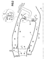
- the combustion chamber is divided circumferentially into adjacent chamber sectors 100 between which are housed seals 13.
- Each chamber sector is made in one piece of ceramic matrix composite material (CMC) and comprises a sector 110 of internal wall, a sector 120 of internal wall and a sector 130 of chamber bottom connecting the sectors 110 and 120.
- CMC ceramic matrix composite material
- the number of sectors 100 forming the entire combustion chamber depends on the ability to integrate several housing injectors when manufacturing a sector and the total number of injectors. For reasons relating to maintenance and repairability of the chamber, each sector may include for example one, two or three housing injectors. In the example shown, the number of sectors is equal to that of the injectors, each sector 100 including an opening 30 is located in the middle of the bottom sector 130.
- the combustion chamber is supported between an inner metal casing 15 and an outer metal casing 25 by means of elastically deformable connecting elements 17, 27.
- the connecting elements 17 connect the metal casing 15 to the wall 10 and the connecting elements 27 connect the metal housing 25 to the wall 20.
- the connecting elements 17, 27 extend in the spaces 16, 26 between the housing 15 and the wall 10 and between the housing 25 and the wall 20, which spaces are traversed by the cooling air flow (arrows f) bypassing the combustion chamber.
- the flexibility of the connecting elements which are advantageously metallic, but can also be in CMC, makes it possible to absorb the differences in dimensional variations of thermal origin between the CMC chamber walls and the metal housings.
- Each chamber sector is connected to the walls 10 and 20 by respectively at least one connecting element 17 and at least one connecting element 27.
- a single connecting element 17 is associated with each chamber sector 100, the element 17 being in the form of a U-shaped metal blade having an end fixed to a lug 18 located on the outside of the wall sector 110 and its other end fixed to the metal housing 15.
- the fixing of the ends of the connecting elements 17 on the legs 18 and the housing 15 can be made by bolting, screwing or riveting.
- a single connecting element 27 is associated with each chamber sector 100, the element 27 being in the form of a U-shaped metal blade having an end fixed to a tab 28 located on the outer side of the wall sector 120 and its other end fixed to the metal housing 25.
- the attachment of the ends of the connecting elements 27 on the lugs 28 and the housing 25 can be achieved by bolting, screwing or riveting.
- the connecting elements 17, as well as the connecting elements 27 are arranged in a circumferential row.
- the connecting elements 17, 27 also contribute to the mutual maintenance of the chamber sectors 100.
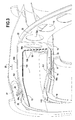
- the chamber sectors are held mutually by fixing the bottom areas 130 of a ring 32 for example of metal, which has openings 32 corresponding to the openings 30 a.
- Fixing the crown 32 may be accomplished by mounting the bowls 34 of the injectors through the openings 30a, 32a, as shown only on the figure 2 , this type of mounting in the bottom openings of the chamber is well known.
- Each injector has a flange that bears on the ring 32 and, on the inner side of the chamber bottom, is fixed at its periphery by welding on a ring 36.
- the fixing of the bottom sectors 130 on the ring 32 could alternatively be performed by screwing or bolting.
- the caps 12, 22, which may be metallic, may be fixed on the inner and outer annular flanges of the ring 32, the fixing being carried out for example by screwing or bolting.
- one of the caps 12, 22 could be made in one piece with the crown 32.
- the sealing lips 19, 29 are fastening tabs 19 a, 29 a which are advantageously fixed to the wall sectors 110, 120 by mechanical connection with the tabs 18, 28, the latter thus serving as both the fixing the connecting elements 17, 27 and fixing the lips 19, 29.
- the sealing lips could be fixed in another way on the wall sectors 110, 120, for example by being connected to tabs or other fastening members integral with the wall sectors and distinct legs 18, 28.
- the tabs 18, 28 are made of CMC and can be fixed to the wall sectors 110, 120 by brazing or integrated with the sectors 100 at the stage of manufacture thereof.
- the sectors 100 are made of CMC having a fiber reinforcement densified by a ceramic matrix.
- the fibers of the fibrous reinforcement may be carbon or ceramic and an interphase for example of pyrolytic carbon (PyC) or boron nitride (BN) may be interposed between the fibers of the reinforcement and the ceramic matrix.
- the fibrous reinforcement can be made by superposition of fibrous layers such as fabrics or webs or by three-dimensional weaving.
- the ceramic matrix may be of silicon carbide or other carbide, nitride or ceramic oxide and may also comprise one or more self-healing matrix phases, that is to say able to heal cracks by passing to the pasty state at a certain temperature.
- CMC materials with a self-healing matrix are described in particular in the patents US 5,965,266 , US 6,291,058 and US 6,068,930 .
- the interphase can be deposited on the fibers of the reinforcement by CVI.
- CVI densification by the ceramic matrix
- a first densification phase for consolidating the fiber reinforcement by maintaining it in the desired shape by means of a tool, the densification then being continued without holding tools.
- CMC parts development processes are well known.
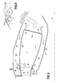
- the integration of the tabs 18, 28 can be carried out at the stage of the development of the fibrous reinforcement by making a local untied reinforcement, a continuity existing between the fibrous reinforcement of the tabs and that of the chamber sectors. A local extra thickness of the reinforcement may then be necessary, which results in an extra thickness 111, 121 of the wall of the sectors 110, 120 as shown in the drawings. figures 3 and 4 . This extra thickness can be partially eliminated by machining in the intervals between the tabs 18, 28.
- the fibrous reinforcements of the tabs 18, 28 may be attached to the fibrous reinforcements of the chamber sectors, for example by sewing or other textile fiber-forming process, before densification.
- the seals 13 are interposed between the longitudinal edges facing the chamber sectors. They have, for example, an X-shaped section.
- the seals 13 can be made in the form of a fibrous structure made of refractory fibers. It is possible to use a non-densified fibrous structure formed of ceramic fibers, for example fibers made of silicon carbide or other carbide, nitride or ceramic oxide, the fibrous structure being obtained for example by weaving or by braiding. It is also possible to use a fibrous structure made of refractory fibers (carbon or ceramic) at least partially densified by a ceramic matrix obtained by CVI or by liquid means.
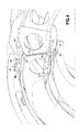
- FIGS 5 and 6 illustrate an alternative embodiment of the connection between the combustion chamber and the HP turbine distributor 40.
- the outer wall sectors 120 extend downstream by end portions 122 which cover the outer face of the inner annular wall 46 of the distributor 40.
- the connection between the end portions 122 and the distributor 40 is realized. by screws 124 which pass through orifices formed in the end portions 122 and screw into threaded (eg) threaded holes formed in the wall 46 and the blades 42.
- the connection could also be made by bolting by means of bolts carried by the wall 46 and passing through the end portions 122.
- the end portions 122 have a reduced width relative to the remainder of the wall sectors 120 to provide a gap 123 between adjacent end portions 122 and thereby allow a differential dimensional variation between the CMC end portions and the metal wall 46 of the dispenser.
- the inner wall sectors 110 extend downstream by end portions 112 of reduced width which cover the outer face of the outer annular wall 44 of the dispenser 40.
- the end portions 112 are connected to each other. to the dispenser by screws 114 or by bolting, in the same way as the end portions 122.
Landscapes
- Engineering & Computer Science (AREA)
- Chemical & Material Sciences (AREA)
- Combustion & Propulsion (AREA)
- Mechanical Engineering (AREA)
- General Engineering & Computer Science (AREA)
- Ceramic Engineering (AREA)
- Turbine Rotor Nozzle Sealing (AREA)
- Gasket Seals (AREA)
Applications Claiming Priority (1)
| Application Number | Priority Date | Filing Date | Title |
|---|---|---|---|
| FR0852232A FR2929690B1 (fr) | 2008-04-03 | 2008-04-03 | Chambre de combustion sectorisee en cmc pour turbine a gaz |
Publications (2)
| Publication Number | Publication Date |
|---|---|
| EP2107308A1 true EP2107308A1 (de) | 2009-10-07 |
| EP2107308B1 EP2107308B1 (de) | 2017-09-06 |
Family
ID=39952180
Family Applications (1)
| Application Number | Title | Priority Date | Filing Date |
|---|---|---|---|
| EP09155277.8A Active EP2107308B1 (de) | 2008-04-03 | 2009-03-16 | In Sektoren unterteilte CMC-Brennkammer für Gasturbine |
Country Status (7)
| Country | Link |
|---|---|
| US (1) | US8141371B1 (de) |
| EP (1) | EP2107308B1 (de) |
| JP (1) | JP5372575B2 (de) |
| KR (1) | KR101576676B1 (de) |
| CN (1) | CN101551122B (de) |
| CA (1) | CA2659982C (de) |
| FR (1) | FR2929690B1 (de) |
Cited By (5)
| Publication number | Priority date | Publication date | Assignee | Title |
|---|---|---|---|---|
| EP2463583A1 (de) * | 2010-12-06 | 2012-06-13 | Alstom Technology Ltd | Gasturbine sowie Verfahren zum Rekonditionieren einer solchen Gasturbine |
| FR3017693A1 (fr) * | 2014-02-19 | 2015-08-21 | Turbomeca | Chambre de combustion de turbomachine |
| EP2402566A3 (de) * | 2010-06-29 | 2018-01-24 | Nuovo Pignone S.p.A. | Hinterkanteneinlagenstützmechanismus und federbelasteter Einlagenstoppmechanismus |
| FR3084446A1 (fr) * | 2018-07-25 | 2020-01-31 | Safran Aircraft Engines | Chambre de combustion monobloc |
| CN112503574A (zh) * | 2020-10-30 | 2021-03-16 | 南京航空航天大学 | 陶瓷基环形火焰筒 |
Families Citing this family (46)
| Publication number | Priority date | Publication date | Assignee | Title |
|---|---|---|---|---|
| FR2953907B1 (fr) * | 2009-12-11 | 2012-11-02 | Snecma | Chambre de combustion pour turbomachine |
| TW201120383A (en) * | 2009-12-15 | 2011-06-16 | Jing Feng Co Ltd | Method of manufacturing combustion chamber of turbo-engine and product thereof. |
| FR2964725B1 (fr) * | 2010-09-14 | 2012-10-12 | Snecma | Carenage aerodynamique pour fond de chambre de combustion |
| US8347636B2 (en) * | 2010-09-24 | 2013-01-08 | General Electric Company | Turbomachine including a ceramic matrix composite (CMC) bridge |
| FR2988777B1 (fr) * | 2012-03-29 | 2014-04-25 | Snecma Propulsion Solide | Integration de pieces d'arriere-corps de moteur aeronautique |
| CN103486619B (zh) * | 2012-06-13 | 2016-02-24 | 中国航空工业集团公司沈阳发动机设计研究所 | 一种火焰筒固定结构 |
| WO2014137428A1 (en) * | 2013-03-05 | 2014-09-12 | Rolls-Royce Corporation | Dual-wall impingement, convection, effusion combustor tile |
| US9423129B2 (en) | 2013-03-15 | 2016-08-23 | Rolls-Royce Corporation | Shell and tiled liner arrangement for a combustor |
| WO2015017084A1 (en) * | 2013-07-30 | 2015-02-05 | Clearsign Combustion Corporation | Combustor having a nonmetallic body with external electrodes |
| DE102015213629A1 (de) * | 2015-07-20 | 2017-01-26 | Rolls-Royce Deutschland Ltd & Co Kg | Abdeckteil und Brennkammerbaugruppe für eine Gasturbine |
| US11149646B2 (en) | 2015-09-02 | 2021-10-19 | General Electric Company | Piston ring assembly for a turbine engine |
| US10168051B2 (en) | 2015-09-02 | 2019-01-01 | General Electric Company | Combustor assembly for a turbine engine |
| US9976746B2 (en) | 2015-09-02 | 2018-05-22 | General Electric Company | Combustor assembly for a turbine engine |
| DE102015224990A1 (de) * | 2015-12-11 | 2017-06-14 | Rolls-Royce Deutschland Ltd & Co Kg | Verfahren zur Montage einer Brennkammer eines Gasturbinentriebwerks |
| US10473332B2 (en) * | 2016-02-25 | 2019-11-12 | General Electric Company | Combustor assembly |
| US10228136B2 (en) | 2016-02-25 | 2019-03-12 | General Electric Company | Combustor assembly |
| US10222065B2 (en) * | 2016-02-25 | 2019-03-05 | General Electric Company | Combustor assembly for a gas turbine engine |
| US10281153B2 (en) | 2016-02-25 | 2019-05-07 | General Electric Company | Combustor assembly |
| US10378771B2 (en) | 2016-02-25 | 2019-08-13 | General Electric Company | Combustor assembly |
| US10317085B2 (en) | 2016-02-25 | 2019-06-11 | General Electric Company | Combustor assembly |
| US10428736B2 (en) | 2016-02-25 | 2019-10-01 | General Electric Company | Combustor assembly |
| US10429070B2 (en) | 2016-02-25 | 2019-10-01 | General Electric Company | Combustor assembly |
| US10393381B2 (en) * | 2017-01-27 | 2019-08-27 | General Electric Company | Unitary flow path structure |
| US10371383B2 (en) * | 2017-01-27 | 2019-08-06 | General Electric Company | Unitary flow path structure |
| US10378770B2 (en) | 2017-01-27 | 2019-08-13 | General Electric Company | Unitary flow path structure |
| US10816199B2 (en) | 2017-01-27 | 2020-10-27 | General Electric Company | Combustor heat shield and attachment features |
| US11111858B2 (en) | 2017-01-27 | 2021-09-07 | General Electric Company | Cool core gas turbine engine |
| US10690347B2 (en) | 2017-02-01 | 2020-06-23 | General Electric Company | CMC combustor deflector |
| US10253643B2 (en) | 2017-02-07 | 2019-04-09 | General Electric Company | Airfoil fluid curtain to mitigate or prevent flow path leakage |
| US10378373B2 (en) | 2017-02-23 | 2019-08-13 | General Electric Company | Flow path assembly with airfoils inserted through flow path boundary |
| US10247019B2 (en) | 2017-02-23 | 2019-04-02 | General Electric Company | Methods and features for positioning a flow path inner boundary within a flow path assembly |
| US10253641B2 (en) | 2017-02-23 | 2019-04-09 | General Electric Company | Methods and assemblies for attaching airfoils within a flow path |
| US10370990B2 (en) | 2017-02-23 | 2019-08-06 | General Electric Company | Flow path assembly with pin supported nozzle airfoils |
| US10385709B2 (en) | 2017-02-23 | 2019-08-20 | General Electric Company | Methods and features for positioning a flow path assembly within a gas turbine engine |
| US10385776B2 (en) | 2017-02-23 | 2019-08-20 | General Electric Company | Methods for assembling a unitary flow path structure |
| US10837640B2 (en) | 2017-03-06 | 2020-11-17 | General Electric Company | Combustion section of a gas turbine engine |
| US10385731B2 (en) | 2017-06-12 | 2019-08-20 | General Electric Company | CTE matching hanger support for CMC structures |
| US11402097B2 (en) | 2018-01-03 | 2022-08-02 | General Electric Company | Combustor assembly for a turbine engine |
| US11181005B2 (en) * | 2018-05-18 | 2021-11-23 | Raytheon Technologies Corporation | Gas turbine engine assembly with mid-vane outer platform gap |
| US12152500B2 (en) | 2018-06-08 | 2024-11-26 | General Electric Company | Composite component modifications |
| US11268394B2 (en) | 2020-03-13 | 2022-03-08 | General Electric Company | Nozzle assembly with alternating inserted vanes for a turbine engine |
| CN113898976B (zh) * | 2020-07-07 | 2022-11-11 | 中国航发商用航空发动机有限责任公司 | 一种燃气轮机的燃烧室及其cmc火焰筒 |
| US11428160B2 (en) | 2020-12-31 | 2022-08-30 | General Electric Company | Gas turbine engine with interdigitated turbine and gear assembly |
| JP7780333B2 (ja) | 2021-12-27 | 2025-12-04 | 川崎重工業株式会社 | 燃焼器のパネル及びそれを備えたガスタービンの燃焼器 |
| CN117917528A (zh) * | 2022-10-20 | 2024-04-23 | 通用电气公司 | 用于燃烧器的整流罩阻尼器 |
| GB202315091D0 (en) * | 2023-10-02 | 2023-11-15 | Rolls Royce Plc | Gas turbine engine |
Citations (17)
| Publication number | Priority date | Publication date | Assignee | Title |
|---|---|---|---|---|
| GB1570875A (en) | 1977-03-16 | 1980-07-09 | Lucas Industries Ltd | Combustion equipment |
| JPS5659131A (en) * | 1979-10-19 | 1981-05-22 | Nissan Motor Co Ltd | Gas turbine combustor |
| EP0706009A2 (de) * | 1994-10-07 | 1996-04-10 | Solar Turbines Incorporated | Keramisches Brennkammerelement mit keilförmigem Rand |
| EP0943867A1 (de) * | 1998-03-17 | 1999-09-22 | Abb Research Ltd. | Keramische Auskleidung einer Brennkammer |
| WO1999048837A1 (en) * | 1998-03-27 | 1999-09-30 | Siemens Westinghouse Power Corporation | Use of high temperature insulation for ceramic matrix composites in gas turbines |
| US5965266A (en) | 1995-03-28 | 1999-10-12 | Societe Nationale D'etude Et De Construction De Moteurs D'aviation | Composite material protected against oxidation by a self-healing matrix, and a method of manufacturing it |
| US6068930A (en) | 1995-12-14 | 2000-05-30 | Societe Nationale D'etude Et De Construction De Moteurs D'aviation | High-temperature composite materials with carbon or carbon-coated fibre reinforcements and enhanced oxidation resistance |
| US6291058B1 (en) | 1996-11-28 | 2001-09-18 | Societe Nationale D'etude Et De Construction De Moteurs D'aviation S.N.E.C.M.A. | Composite material with ceramic matrix and SiC fiber reinforcement, method for making same |
| US6708495B2 (en) | 2001-06-06 | 2004-03-23 | Snecma Moteurs | Fastening a CMC combustion chamber in a turbomachine using brazed tabs |
| FR2871847A1 (fr) * | 2004-06-17 | 2005-12-23 | Snecma Moteurs Sa | Montage d'un distributeur de turbine sur une chambre de combustion a parois en cmc dans une turbine a gaz |
| EP1635118A2 (de) | 2004-09-10 | 2006-03-15 | DLR Deutsches Zentrum für Luft- und Raumfahrt e.V. | Heissgaskammer und Schindel für eine Heissgaskammer |
| EP1731839A2 (de) * | 2005-06-07 | 2006-12-13 | Snecma | Vorrichtung zum Anbringen einer Einspritzungvorrichtung am Boden einer Turbinenbrennkammer und Verfahren zum Anbringen |
| GB2432902A (en) * | 2005-12-03 | 2007-06-06 | Alstom Technology Ltd | A Support for a Gas Turbine Combustion Liner Segment |
| US7234306B2 (en) | 2004-06-17 | 2007-06-26 | Snecma | Gas turbine combustion chamber made of CMC and supported in a metal casing by CMC linking members |
| EP1801502A2 (de) * | 2005-12-22 | 2007-06-27 | United Technologies Corporation | Doppelwandige Brennkammerwand |
| US7237388B2 (en) | 2004-06-17 | 2007-07-03 | Snecma | Assembly comprising a gas turbine combustion chamber integrated with a high pressure turbine nozzle |
| US7237387B2 (en) | 2004-06-17 | 2007-07-03 | Snecma | Mounting a high pressure turbine nozzle in leaktight manner to one end of a combustion chamber in a gas turbine |
Family Cites Families (3)
| Publication number | Priority date | Publication date | Assignee | Title |
|---|---|---|---|---|
| US3956886A (en) * | 1973-12-07 | 1976-05-18 | Joseph Lucas (Industries) Limited | Flame tubes for gas turbine engines |
| US6610385B2 (en) * | 2001-12-20 | 2003-08-26 | General Electric Company | Integral surface features for CMC components and method therefor |
| FR2897417A1 (fr) * | 2006-02-10 | 2007-08-17 | Snecma Sa | Chambre de combustion annulaire d'une turbomachine |
-
2008
- 2008-04-03 FR FR0852232A patent/FR2929690B1/fr active Active
-
2009
- 2009-03-16 EP EP09155277.8A patent/EP2107308B1/de active Active
- 2009-03-25 CA CA2659982A patent/CA2659982C/en active Active
- 2009-04-01 US US12/416,422 patent/US8141371B1/en active Active
- 2009-04-02 CN CN2009101336184A patent/CN101551122B/zh active Active
- 2009-04-03 KR KR1020090028809A patent/KR101576676B1/ko active Active
- 2009-04-03 JP JP2009090584A patent/JP5372575B2/ja active Active
Patent Citations (17)
| Publication number | Priority date | Publication date | Assignee | Title |
|---|---|---|---|---|
| GB1570875A (en) | 1977-03-16 | 1980-07-09 | Lucas Industries Ltd | Combustion equipment |
| JPS5659131A (en) * | 1979-10-19 | 1981-05-22 | Nissan Motor Co Ltd | Gas turbine combustor |
| EP0706009A2 (de) * | 1994-10-07 | 1996-04-10 | Solar Turbines Incorporated | Keramisches Brennkammerelement mit keilförmigem Rand |
| US5965266A (en) | 1995-03-28 | 1999-10-12 | Societe Nationale D'etude Et De Construction De Moteurs D'aviation | Composite material protected against oxidation by a self-healing matrix, and a method of manufacturing it |
| US6068930A (en) | 1995-12-14 | 2000-05-30 | Societe Nationale D'etude Et De Construction De Moteurs D'aviation | High-temperature composite materials with carbon or carbon-coated fibre reinforcements and enhanced oxidation resistance |
| US6291058B1 (en) | 1996-11-28 | 2001-09-18 | Societe Nationale D'etude Et De Construction De Moteurs D'aviation S.N.E.C.M.A. | Composite material with ceramic matrix and SiC fiber reinforcement, method for making same |
| EP0943867A1 (de) * | 1998-03-17 | 1999-09-22 | Abb Research Ltd. | Keramische Auskleidung einer Brennkammer |
| WO1999048837A1 (en) * | 1998-03-27 | 1999-09-30 | Siemens Westinghouse Power Corporation | Use of high temperature insulation for ceramic matrix composites in gas turbines |
| US6708495B2 (en) | 2001-06-06 | 2004-03-23 | Snecma Moteurs | Fastening a CMC combustion chamber in a turbomachine using brazed tabs |
| FR2871847A1 (fr) * | 2004-06-17 | 2005-12-23 | Snecma Moteurs Sa | Montage d'un distributeur de turbine sur une chambre de combustion a parois en cmc dans une turbine a gaz |
| US7234306B2 (en) | 2004-06-17 | 2007-06-26 | Snecma | Gas turbine combustion chamber made of CMC and supported in a metal casing by CMC linking members |
| US7237388B2 (en) | 2004-06-17 | 2007-07-03 | Snecma | Assembly comprising a gas turbine combustion chamber integrated with a high pressure turbine nozzle |
| US7237387B2 (en) | 2004-06-17 | 2007-07-03 | Snecma | Mounting a high pressure turbine nozzle in leaktight manner to one end of a combustion chamber in a gas turbine |
| EP1635118A2 (de) | 2004-09-10 | 2006-03-15 | DLR Deutsches Zentrum für Luft- und Raumfahrt e.V. | Heissgaskammer und Schindel für eine Heissgaskammer |
| EP1731839A2 (de) * | 2005-06-07 | 2006-12-13 | Snecma | Vorrichtung zum Anbringen einer Einspritzungvorrichtung am Boden einer Turbinenbrennkammer und Verfahren zum Anbringen |
| GB2432902A (en) * | 2005-12-03 | 2007-06-06 | Alstom Technology Ltd | A Support for a Gas Turbine Combustion Liner Segment |
| EP1801502A2 (de) * | 2005-12-22 | 2007-06-27 | United Technologies Corporation | Doppelwandige Brennkammerwand |
Cited By (11)
| Publication number | Priority date | Publication date | Assignee | Title |
|---|---|---|---|---|
| EP2402566A3 (de) * | 2010-06-29 | 2018-01-24 | Nuovo Pignone S.p.A. | Hinterkanteneinlagenstützmechanismus und federbelasteter Einlagenstoppmechanismus |
| EP2463583A1 (de) * | 2010-12-06 | 2012-06-13 | Alstom Technology Ltd | Gasturbine sowie Verfahren zum Rekonditionieren einer solchen Gasturbine |
| CH704185A1 (de) * | 2010-12-06 | 2012-06-15 | Alstom Technology Ltd | Gasturbine sowie verfahren zum rekonditionieren einer solchen gasturbine. |
| AU2011253595B2 (en) * | 2010-12-06 | 2015-07-16 | General Electric Technology Gmbh | Gas turbine and method for reconditioning such a gas turbine |
| FR3017693A1 (fr) * | 2014-02-19 | 2015-08-21 | Turbomeca | Chambre de combustion de turbomachine |
| WO2015124840A1 (fr) * | 2014-02-19 | 2015-08-27 | Turbomeca | Chambre de combustion annulaire de turbomachine |
| US9933164B2 (en) | 2014-02-19 | 2018-04-03 | Safran Helicopter Engines | Annular turbomachine combustion chamber |
| RU2669435C2 (ru) * | 2014-02-19 | 2018-10-11 | Сафран Хеликоптер Энджинз | Кольцевая камера сгорания турбомашины |
| FR3084446A1 (fr) * | 2018-07-25 | 2020-01-31 | Safran Aircraft Engines | Chambre de combustion monobloc |
| US11333358B2 (en) | 2018-07-25 | 2022-05-17 | Safran Aircraft Engines | One-piece combustion chamber |
| CN112503574A (zh) * | 2020-10-30 | 2021-03-16 | 南京航空航天大学 | 陶瓷基环形火焰筒 |
Also Published As
| Publication number | Publication date |
|---|---|
| CA2659982A1 (en) | 2009-10-03 |
| CN101551122A (zh) | 2009-10-07 |
| FR2929690A1 (fr) | 2009-10-09 |
| KR101576676B1 (ko) | 2015-12-21 |
| US8141371B1 (en) | 2012-03-27 |
| EP2107308B1 (de) | 2017-09-06 |
| CN101551122B (zh) | 2012-10-17 |
| JP5372575B2 (ja) | 2013-12-18 |
| FR2929690B1 (fr) | 2012-08-17 |
| US20120073306A1 (en) | 2012-03-29 |
| CA2659982C (en) | 2016-06-07 |
| KR20090105880A (ko) | 2009-10-07 |
| JP2009293914A (ja) | 2009-12-17 |
Similar Documents
| Publication | Publication Date | Title |
|---|---|---|
| EP2107308B1 (de) | In Sektoren unterteilte CMC-Brennkammer für Gasturbine | |
| EP2107307B1 (de) | Gasturbinenbrennkammer mit in Sektoren unterteilten Innen- und Außenwänden | |
| EP2142787B1 (de) | Mehrstromige gasturbine mit einer abgasvorrichtung | |
| EP1797310B1 (de) | Mischer für eine düse mit getrenntem durchfluss | |
| EP2132426B1 (de) | Cmc-mischer mit struktureller aussenverschalung | |
| EP3271556B1 (de) | Vorrichtung von turbinenringen mit mehreren teilringen aus keramik-verbundswerkstoffen | |
| EP3298245B1 (de) | Turbinenringanordnung mit einer befestigung in der art einer klauenkupplung | |
| EP2137384B1 (de) | Turbinenringanordnung für eine gasturbine | |
| FR3036435A1 (fr) | Ensemble d'anneau de turbine | |
| FR3036436A1 (fr) | Ensemble d'anneau de turbine avec maintien par brides | |
| FR2913717A1 (fr) | Ensemble d'anneau de turbine pour turbine a gaz | |
| EP2329197B1 (de) | Vorrichtung zur befestigung eines flammhalterarms an einem nachbrennergehäuse | |
| FR2914707A1 (fr) | Procede d'assemblage avec recouvrement de deux pieces ayant des coefficients de dilatation differents et assemblage ainsi obtenu | |
| EP1265032A1 (de) | Gasturbinenbrennkammer aus Verbundwerkstoff mit keramischer Matrix | |
| EP3274565B1 (de) | Turbinenringanordnung mit besonderer haltevorrichtung von ringsegmenten aus keramischen faserverbundwerkstoff | |
| EP1557553A1 (de) | Einblockarm für eine Nachverbrennungsvorrichtung eines Triebwerkes mit Doppelströmung | |
| FR3041994A1 (fr) | Ensemble d'anneau de turbine | |
| FR3027959A1 (fr) | Protection anti-feu d'une piece en materiau composite d'une turbine a gaz | |
| FR3129678A1 (fr) | Piece pour une turbomachine comportant un revêtement de barriere thermique en geopolymere | |
| FR3084445A1 (fr) | Fabrication d'une chambre de combustion en materiau composite |
Legal Events
| Date | Code | Title | Description |
|---|---|---|---|
| PUAI | Public reference made under article 153(3) epc to a published international application that has entered the european phase |
Free format text: ORIGINAL CODE: 0009012 |
|
| 17P | Request for examination filed |
Effective date: 20090316 |
|
| AK | Designated contracting states |
Kind code of ref document: A1 Designated state(s): AT BE BG CH CY CZ DE DK EE ES FI FR GB GR HR HU IE IS IT LI LT LU LV MC MK MT NL NO PL PT RO SE SI SK TR |
|
| AX | Request for extension of the european patent |
Extension state: AL BA RS |
|
| 17Q | First examination report despatched |
Effective date: 20100311 |
|
| AKX | Designation fees paid |
Designated state(s): DE FR GB IT |
|
| GRAP | Despatch of communication of intention to grant a patent |
Free format text: ORIGINAL CODE: EPIDOSNIGR1 |
|
| INTG | Intention to grant announced |
Effective date: 20170208 |
|
| GRAS | Grant fee paid |
Free format text: ORIGINAL CODE: EPIDOSNIGR3 |
|
| GRAJ | Information related to disapproval of communication of intention to grant by the applicant or resumption of examination proceedings by the epo deleted |
Free format text: ORIGINAL CODE: EPIDOSDIGR1 |
|
| GRAL | Information related to payment of fee for publishing/printing deleted |
Free format text: ORIGINAL CODE: EPIDOSDIGR3 |
|
| INTC | Intention to grant announced (deleted) | ||
| GRAR | Information related to intention to grant a patent recorded |
Free format text: ORIGINAL CODE: EPIDOSNIGR71 |
|
| GRAA | (expected) grant |
Free format text: ORIGINAL CODE: 0009210 |
|
| AK | Designated contracting states |
Kind code of ref document: B1 Designated state(s): DE FR GB IT |
|
| INTG | Intention to grant announced |
Effective date: 20170801 |
|
| REG | Reference to a national code |
Ref country code: GB Ref legal event code: FG4D Free format text: NOT ENGLISH |
|
| REG | Reference to a national code |
Ref country code: DE Ref legal event code: R096 Ref document number: 602009048133 Country of ref document: DE |
|
| REG | Reference to a national code |
Ref country code: FR Ref legal event code: PLFP Year of fee payment: 10 |
|
| REG | Reference to a national code |
Ref country code: DE Ref legal event code: R097 Ref document number: 602009048133 Country of ref document: DE |
|
| PLBE | No opposition filed within time limit |
Free format text: ORIGINAL CODE: 0009261 |
|
| STAA | Information on the status of an ep patent application or granted ep patent |
Free format text: STATUS: NO OPPOSITION FILED WITHIN TIME LIMIT |
|
| 26N | No opposition filed |
Effective date: 20180607 |
|
| PGFP | Annual fee paid to national office [announced via postgrant information from national office to epo] |
Ref country code: IT Payment date: 20250218 Year of fee payment: 17 |
|
| PGFP | Annual fee paid to national office [announced via postgrant information from national office to epo] |
Ref country code: GB Payment date: 20260324 Year of fee payment: 18 |
|
| PGFP | Annual fee paid to national office [announced via postgrant information from national office to epo] |
Ref country code: DE Payment date: 20260320 Year of fee payment: 18 |
|
| PGFP | Annual fee paid to national office [announced via postgrant information from national office to epo] |
Ref country code: FR Payment date: 20260324 Year of fee payment: 18 |