EP2137384B1 - Turbinenringanordnung für eine gasturbine - Google Patents
Turbinenringanordnung für eine gasturbine Download PDFInfo
- Publication number
- EP2137384B1 EP2137384B1 EP08788004A EP08788004A EP2137384B1 EP 2137384 B1 EP2137384 B1 EP 2137384B1 EP 08788004 A EP08788004 A EP 08788004A EP 08788004 A EP08788004 A EP 08788004A EP 2137384 B1 EP2137384 B1 EP 2137384B1
- Authority
- EP
- European Patent Office
- Prior art keywords
- ring
- cmc
- turbine
- assembly according
- ring assembly
- Prior art date
- Legal status (The legal status is an assumption and is not a legal conclusion. Google has not performed a legal analysis and makes no representation as to the accuracy of the status listed.)
- Active
Links
Images


Classifications
-
- F—MECHANICAL ENGINEERING; LIGHTING; HEATING; WEAPONS; BLASTING
- F01—MACHINES OR ENGINES IN GENERAL; ENGINE PLANTS IN GENERAL; STEAM ENGINES
- F01D—NON-POSITIVE DISPLACEMENT MACHINES OR ENGINES, e.g. STEAM TURBINES
- F01D11/00—Preventing or minimising internal leakage of working-fluid, e.g. between stages
- F01D11/08—Preventing or minimising internal leakage of working-fluid, e.g. between stages for sealing space between rotor blade tips and stator
-
- F—MECHANICAL ENGINEERING; LIGHTING; HEATING; WEAPONS; BLASTING
- F01—MACHINES OR ENGINES IN GENERAL; ENGINE PLANTS IN GENERAL; STEAM ENGINES
- F01D—NON-POSITIVE DISPLACEMENT MACHINES OR ENGINES, e.g. STEAM TURBINES
- F01D11/00—Preventing or minimising internal leakage of working-fluid, e.g. between stages
- F01D11/08—Preventing or minimising internal leakage of working-fluid, e.g. between stages for sealing space between rotor blade tips and stator
- F01D11/12—Preventing or minimising internal leakage of working-fluid, e.g. between stages for sealing space between rotor blade tips and stator using a rubstrip, e.g. erodible. deformable or resiliently-biased part
- F01D11/122—Preventing or minimising internal leakage of working-fluid, e.g. between stages for sealing space between rotor blade tips and stator using a rubstrip, e.g. erodible. deformable or resiliently-biased part with erodable or abradable material
- F01D11/125—Preventing or minimising internal leakage of working-fluid, e.g. between stages for sealing space between rotor blade tips and stator using a rubstrip, e.g. erodible. deformable or resiliently-biased part with erodable or abradable material with a reinforcing structure
-
- F—MECHANICAL ENGINEERING; LIGHTING; HEATING; WEAPONS; BLASTING
- F05—INDEXING SCHEMES RELATING TO ENGINES OR PUMPS IN VARIOUS SUBCLASSES OF CLASSES F01-F04
- F05D—INDEXING SCHEME FOR ASPECTS RELATING TO NON-POSITIVE-DISPLACEMENT MACHINES OR ENGINES, GAS-TURBINES OR JET-PROPULSION PLANTS
- F05D2250/00—Geometry
- F05D2250/20—Three-dimensional
- F05D2250/23—Three-dimensional prismatic
- F05D2250/232—Three-dimensional prismatic conical
-
- F—MECHANICAL ENGINEERING; LIGHTING; HEATING; WEAPONS; BLASTING
- F05—INDEXING SCHEMES RELATING TO ENGINES OR PUMPS IN VARIOUS SUBCLASSES OF CLASSES F01-F04
- F05D—INDEXING SCHEME FOR ASPECTS RELATING TO NON-POSITIVE-DISPLACEMENT MACHINES OR ENGINES, GAS-TURBINES OR JET-PROPULSION PLANTS
- F05D2260/00—Function
- F05D2260/30—Retaining components in desired mutual position
-
- F—MECHANICAL ENGINEERING; LIGHTING; HEATING; WEAPONS; BLASTING
- F05—INDEXING SCHEMES RELATING TO ENGINES OR PUMPS IN VARIOUS SUBCLASSES OF CLASSES F01-F04
- F05D—INDEXING SCHEME FOR ASPECTS RELATING TO NON-POSITIVE-DISPLACEMENT MACHINES OR ENGINES, GAS-TURBINES OR JET-PROPULSION PLANTS
- F05D2300/00—Materials; Properties thereof
- F05D2300/50—Intrinsic material properties or characteristics
- F05D2300/502—Thermal properties
- F05D2300/5021—Expansivity
-
- F—MECHANICAL ENGINEERING; LIGHTING; HEATING; WEAPONS; BLASTING
- F05—INDEXING SCHEMES RELATING TO ENGINES OR PUMPS IN VARIOUS SUBCLASSES OF CLASSES F01-F04
- F05D—INDEXING SCHEME FOR ASPECTS RELATING TO NON-POSITIVE-DISPLACEMENT MACHINES OR ENGINES, GAS-TURBINES OR JET-PROPULSION PLANTS
- F05D2300/00—Materials; Properties thereof
- F05D2300/60—Properties or characteristics given to material by treatment or manufacturing
- F05D2300/603—Composites; e.g. fibre-reinforced
-
- F—MECHANICAL ENGINEERING; LIGHTING; HEATING; WEAPONS; BLASTING
- F05—INDEXING SCHEMES RELATING TO ENGINES OR PUMPS IN VARIOUS SUBCLASSES OF CLASSES F01-F04
- F05D—INDEXING SCHEME FOR ASPECTS RELATING TO NON-POSITIVE-DISPLACEMENT MACHINES OR ENGINES, GAS-TURBINES OR JET-PROPULSION PLANTS
- F05D2300/00—Materials; Properties thereof
- F05D2300/60—Properties or characteristics given to material by treatment or manufacturing
- F05D2300/614—Fibres or filaments
-
- Y—GENERAL TAGGING OF NEW TECHNOLOGICAL DEVELOPMENTS; GENERAL TAGGING OF CROSS-SECTIONAL TECHNOLOGIES SPANNING OVER SEVERAL SECTIONS OF THE IPC; TECHNICAL SUBJECTS COVERED BY FORMER USPC CROSS-REFERENCE ART COLLECTIONS [XRACs] AND DIGESTS
- Y02—TECHNOLOGIES OR APPLICATIONS FOR MITIGATION OR ADAPTATION AGAINST CLIMATE CHANGE
- Y02T—CLIMATE CHANGE MITIGATION TECHNOLOGIES RELATED TO TRANSPORTATION
- Y02T50/00—Aeronautics or air transport
- Y02T50/60—Efficient propulsion technologies, e.g. for aircraft
Definitions
- the invention relates to turbine rings for gas turbines, whether they are industrial gas turbines or aeronautical engine gas turbines.
- a turbine ring defines a flow stream of gas flow through the turbine at a moving wheel thereof. To ensure the best possible performance, it is important to avoid a direct passage of gas between the tops of the vanes of the turbine wheel and the inner surface of the ring.
- a turbine ring is provided on its inner face with a layer of abradable material with which the blade tips can come into contact without appreciable damage under the effect of dimensional variations of thermal origin or resulting the centrifugal force applied to the blades.
- the turbine rings are usually made of several adjacent sectors of metal material.
- thermostructural composite material more particularly a ceramic matrix composite material (or CMC).
- CMC ceramic matrix composite material
- the aim of the invention is to propose a simplified assembly for a CMC turbine ring also making it possible to minimize gas leaks between the vein in which a turbine wheel is located opposite the ring and a support structure of the turbine. 'ring.
- the metal structure comprises two metal annular supports between which the CMC ring is mounted.
- the element exerting an elastic restoring force may be an elastically deformable prestressed blade bearing, on the one hand, on the annular supports and, on the other hand, on the wedge-shaped piece.
- the metal structure comprises a metal crown encircling the outer peripheral surface of the CMC ring.
- the element exerting an elastic restoring force may then be a resiliently deformable preloading tongue integral with the metal crown and resting on the wedge-shaped part.
- the metal structure may further comprise two annular metal supports between which the CMC ring and the metal ring are mounted, allowing a differential expansion at least in radial direction between, on the one hand, the metal ring and on the other hand , the annular metal supports.
- means are provided for centering the metal ring and the CMC ring.
- the metal ring can be mounted between the annular metal supports by means of elastically deformable blades.
- a seal is interposed between at least one of the lateral faces of the CMC ring and a face facing one of said annular metal supports.
- the wedge-shaped piece has an inner end face substantially in continuity with the inner circumferential surface of the CMC ring at the temperature at which the ring assembly turbine is normally exposed in service.
- the CMC ring may be provided with a layer of abradable material on its inner peripheral surface.
- the material of the CMC ring is a self-healing ceramic matrix composite material.
- the material of the CMC ring may be provided with an environmental barrier coating for protection against corrosion.
- the CMC ring comprises a fibrous reinforcement formed by three-dimensional weaving.
- the CMC ring and the wedge-shaped piece are made of the same material.
- FIG. 1 are represented very schematically, from upstream to downstream in the flow direction of gas flow in a gas turbine, a combustion chamber 1, a turbine distributor 2 disposed at the outlet of the combustion chamber , a high-pressure turbine (HP) 3, a flow rectifier 4 and a first stage of a low-pressure turbine (LP) 5.
- HP high-pressure turbine
- LP low-pressure turbine
- the HP turbine 3 comprises a rotating wheel 6 carrying vanes 7 and a turbine ring assembly.
- the turbine ring assembly comprises a split, one-piece turbine ring of CMC material.
- the CMC ring is supported by a metal structure comprising upstream and downstream metal annular supports 40 between which the ring 10 is disposed.
- the metal supports 30 and 40 are connected to a turbine housing 8.
- An annular space 9 is formed outside of the ring 10, between supports 30, 40, delimited by a bottom wall 9 a. Cooling air is fed into the annular space 9 in a manner well known per se.
- the ring 10 In its lateral parts, the ring 10 has its lateral faces 12 a, 12 b adjacent the bottom walls 32 a, 42 a of said housing and is supported by its outer peripheral surface 14 of the cylindrical walls Device 32 b, 42 b of the same housing ( figure 3A ).
- the split ring 10 is inserted with circumferential prestress in the housings of the supports 30, 40, within the limit of its elastic deformation capacity so that, as explained also below, the contact with support between the ring 10 and the walls cylindrical 32 b , 42 b remains maintained in case of thermal expansion of the supports 30, 40, the metallic material thereof having a coefficient of expansion greater than that of the CMC material of the ring 10.
- the ring 10 When cold, the ring 10 is almost closed, the space between its ends being small.
- the ring 10 has its end portions 10 a, 10 b beveled, and a closure part 20 in a wedge shape is applied to the beveled surfaces 15 a, 15 b of the end portions of the ring 10 ( Figures 5A, 5B ).
- the piece 20 has a section that is substantially trapezoidal, with a rear face 22 a and a front face 22 b of smaller length which connects to the rear face 22 has inclined side faces 24a, 24b which come into pressing the bevelled surfaces 15 a, 15 b and have substantially the same inclination as them.
- the part 20 is made of CMC material, preferably the same material as that of the ring 10, and has a width substantially equal to that of the ring 10.
- the piece 20 is applied to the beveled end portions of the ring 10 with an elastic bearing force exerted by an elastically deformable metal blade 26 which is housed in the prestressed state between the rear face 22 a of the piece 20 and bottom walls 36 a, 46 a of housing 36, 46 arranged along an area the annular supports 30 and 40, from their inner faces 32, 42 ( Figures 3B and 4 ).
- the blade 26 has a curved shape with its central portion supported on the part 20 and its end portions supported on the walls 36 a, 46 a.
- the front face 22b of the part 20 has a circular profile of radius substantially equal to that of the inner peripheral surface 16 of the ring 10.
- FIGS. 5A and 5B show the relative positions of the ring 10 and the part 20 respectively cold and hot, that is to say the operating temperature reached during normal operation of a gas turbine in which the Turbine ring assembly is mounted.
- the piece 20 When cold, the piece 20 is set back from the surface internal ring 16 of the ring 10.
- the slot of the ring 10 opens because the ring 10, having been mounted with prestressing, "follows" the expansion of the metal annular supports 30, 40.
- the dimensions of the piece 20 are chosen so that hot, depending on the differential expansion between the ring 10 and the supports 30, 40, the front face 22 b of the part 20 is substantially in the continuity of the inner surface 16 of the ring 10, the flexible blade 26 always exerting a bearing force on the part 20.
- the permanent support with prestressing between the outer surface 14 of the ring 10 and the surfaces 32 b , 42 b ensures the centering
- This permanent support also makes it possible to limit the leaks between the outside of the ring 10 and the flow stream of hot gas flow inside the ring 10.
- cooling air leaks in the hot gas stream may if desired be further minimized by providing an annular seal between the ring 10 and the downstream annular support 40.
- the ring 10 is provided with a layer 11 of abradable material with which blade tips of a mobile wheel surrounded by the ring 10 can come into contact without significant damage.
- the layer 11 is disposed in an annular housing 18 formed in the inner surface 16 over most of the width of the ring 10 in the axial direction.
- the exposed face of the layer 11, the inner surface portions 16 located on either side thereof and the inner peripheral surfaces 38, 48 of the annular metal supports 30, 40 define a continuous surface. of hot gas flow vein with no sudden change in diameter.
- a layer 21 of abradable material is advantageously formed on the front face 22b of the part 20 so as to come to hot, in the continuity of layer 11.
- Blocking of the ring 10 in rotation relative to the annular supports 30, 40 or at least one of them is realized. This prevents a contact between a mobile wheel blade tip and the coating abradable 11 causes rotation of the ring.
- the locking in rotation is for example carried out by means of teeth 35, 45 ( figure 6 ) Projecting from the walls 32, 42 and engaging grooves formed in the side faces 12 a, 12 b of the ring 10.
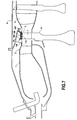
- the figure 7 is a partial schematic view in axial half-section of a gas turbine which differs from the figure 1 essentially by the way the CMC split turbine ring 110 is mounted between annular metal supports 130, 140, the other elements of the gas turbine being similar to those of the figure 1 and bearing the same references.
- the split ring 110 is mounted with circumferential prestressing in a metal ring 150, within the limit of its elastic deformation capacity.
- the assembly is carried out so that the contact with support between the outer peripheral surface of the ring 110 and the inner surface of the ring 150 remains maintained in the event of expansion of thermal origin at the temperatures encountered in use by the ring assembly turbine, the metal material of the ring 150 having a coefficient of expansion greater than that of the CMC material of the ring 110.
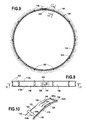
- the ring 150 has a width slightly smaller than that of the ring 110, its side edges being set back side faces 112 a, 112 b of the ring 110 ( Figures 8, 12 ).
- the ring 110 When cold, the ring 110 is almost closed, the space between its ends being weak.
- the ring 110 has its end portions 110 a, 110 b and a bevelled wedge-shaped closure part 120 is applied to the beveled surfaces 115 a, 115 b of the end of the ring portions ( Figures 9, 10 , 11 ).
- Part 120 is similar to part 20 of the previous embodiment. It has a rear face 122 has a front surface 122 b having a curvature substantially equal to that of the inner peripheral surface 116 of the ring 110, and side faces 124 a, 124 b bearing on the beveled surfaces 115a , 115 b .
- the piece 120 is made of CMC material, preferably the same as that of the ring 110 and has a width substantially equal to that of the ring 110.
- the piece 120 is applied to the beveled end portions of the ring 110 with an elastic bearing force exerted by an elastically deformable tongue 156.
- the ring 150 deviates from the ring on a portion 158 of larger diameter which connects with the remainder of the ring and provides space for the piece 120 at the end portions of the ring 110, that remaining, over most of its contour, bearing on the inner surface of the ring 150.
- the tongue 156 is cut in the circumferential direction in the central zone of the portion 158 of the ring 150 by staying connected to it at one end.
- the tongue After cutting, the tongue is deformed to be bent and bear on the piece 120 by exerting on it an elastic force, including when the piece 120 is hot close the slot of the ring 110 with the front face 122 b substantially in the continuity of the inner surface 116 of the ring 110.
- an elastic force including when the piece 120 is hot close the slot of the ring 110 with the front face 122 b substantially in the continuity of the inner surface 116 of the ring 110.
- other forms of elastically deformable parts exerting a bearing force on the part 120 for example a blade similar to that of the previous realization.
- the ring 110 provided with the ring 150 is disposed between the metal annular supports 130, 140, the side faces 112 a, 112 b of the ring being adjacent to the inner side faces 132, 142 of the supports 130, 140 located facing the ring 110.
- the ring 110 provided with the crown 150 is held between the supports 130, 140 by means of metal strips 160 that are elastically deformable ( Figures 8, 10 , 12 radially extending.
- a plurality of blades 160 preferably distributed regularly around the axis of the ring 110 are provided, their number being at least equal to 3.
- Each blade 160 has a central portion 162 connected to the outer surface 152 of the ring 150 which connects to the curved side portions 162 a, 162 b away from the surface 152. the ends of the side portions 162 a, 162 b are engaged in corresponding recesses 134, 144 formed in the sides 132, 142 of the supports 130, 140.
- the blades 160 are connected to the outer surface 152 of the ring 150 for example by clipping, welding or riveting.
- the blades 160 have hooks 164 a, 164 b on either side of their central portion 162, which hooks are engaged with elastic deformation in housings formed on the outer surface 152 of the ring gear 150 ( figure 10 ).
- the blades 160 make it possible to maintain the desired centering of the ring 110 provided with the ring gear 150 while allowing differential expansion in the radial direction between, on the one hand, the annular supports 130, 140 and, on the other hand, the crown 150. As indicated above with respect to the first embodiment, it may be desirable to minimize or control leaks between the outside of the ring 110 and the hot gas flow stream within the ring. 110, at least on the side of the downstream annular support 140.
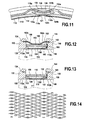
- an elastic washer 166 is disposed in a groove 143 formed in the inner surface 142 of the annular support 140 ( Figures 12, 13 ).
- the spring washer is prestressed and is supported at its outer circumferential end against the bottom of the groove 143 and, at its inner circumferential end, against a bearing washer 168 bears against the side face 112 b of the ring 110.
- a à profile seal could be used.
- Holes may be made in the spring washer 166 in order to balance the pressure in the groove 143 on either side of the washer 166 and to provide a cooling air flow rate for the annular support 140.
- the ring 110 is provided with a layer of abradable material 111.
- the layer 111 is disposed in an annular housing 118 formed in the inner surface 116 of the ring 110 of to define, with the inner peripheral surfaces 138, 148 of the annular metal supports 130, 140 a continuous surface of hot gas stream without abrupt variation in diameter.
- a similar abradable coating 121 is formed on the front face 122a of the part 120.
- the ring 110 provided with the ring gear 150 is locked against the supports 130, 140 or with respect to at least one of them.
- the locking in rotation is achieved for example by means of pins 159 ( figure 13 ) integral with the crown 150 and engaging in blind holes formed in the outer face of the ring 110.
- the ring 150 As for the ring 150, it is locked in rotation relative to the supports 130, 140 by means of the blades 160 whose ends are engaged in the recesses 134, 144 of the faces 132, 142 Alternatively, recesses 134, 144 may be provided in the form of continuous grooves or grooves in which case the locking of the ring gear 150 relative to the supports 130, 140 is effected by other means, for example by forming on at least one of the faces 132, 142 one or more teeth each engaging in a notch formed in the ring 150 and possibly the ring 110.
- the CMC material of the ring 10 or 110 and the part 20 or 120 may be of known type per se obtained by densification of a fibrous preform by a ceramic matrix, the fibrous preform providing the fibrous reinforcement of the material.
- the fibers of the preform are refractory fibers such as carbon fibers or ceramic fibers, for example silicon carbide (SiC). It will be noted that the term “ceramic” also covers compounds of the refractory oxide type.
- a first step may consist in producing a fiber preform which, after densification by the ceramic matrix, makes it possible to obtain a part in which the ring 10, 110 or the wedge-shaped part 20, 120 can be machined or cut.
- the machining is preferably performed at an intermediate densification stage to ensure that after a final final step of densification, the fibers of the fiber preform are well protected by a matrix layer.
- One embodiment of a fiber preform for the ring 10 or 110 consists of producing a strip of desired thickness by three-dimensional weaving.
- the figure 14 schematically illustrates an interlock type armor usable for three-dimensional weaving (the weft son being in section).
- the end portions of the woven strip may be made with decreasing thickness corresponding to the beveled ends of the ring.
- a decreasing thickness can be obtained during weaving by gradually decreasing the number of layers of warp and weft son.
- Three-dimensional weave armor other than interlock type armor can be used such as multi-layer weaves, for example of multi-fabric or multi-satin type as those described in the document WO 2006/136755 .
- a fiber preform for the ring 10 or 110 may be envisaged.
- a strip of desired thickness may be formed by superposing several fibrous layers, for example strips of fabric, and binding the strips together, for example by needling.
- the ceramic matrix may be a refractory ceramic matrix, such as SiC or, advantageously, a "self-healing" ceramic matrix.
- a "self-healing" ceramic matrix is obtained by performing at least one constituent phase of the matrix in a material capable, by passing to the viscous state in a certain temperature range, to fill or "heal" cracks formed in the matrix especially under the effect of thermal cycling.
- Compositions having "self-healing" properties include vitreous compositions, for example of aluminosilicate type, or compositions capable, under the effect of oxidation, of forming glassy compositions.
- B 4 C boron carbide matrix phases or a Si-BC ternary system are precursors of glassy compositions.
- the matrix may be formed by chemical vapor infiltration, or CVI ("Chemical Vapor Infiltration"), and an interphase coating for example pyrolytic carbon PyC or boron nitride BN may be previously formed on the fibers of the preform.
- CVI Chemical Vapor Infiltration
- the fibrous preform can be maintained in the desired shape during a first densification phase until consolidation of the preform, i.e. sufficient partial densification so that the preform can then retain its shape without the assistance of tooling.
- Processes for producing "self-healing" ceramic matrix composite material are described in particular in the documents US 5,965,266 , US 6,291,058 and US 6,068,930 .
- the CMC material can be protected against corrosion by an environmental protection barrier, in a manner known per se.
- a barrier may for example comprise an outer yttria stabilized zirconia layer and a mullite bonding sub-layer. It is also known to provide resistance against corrosion by a layer of a type compound alkaline earth metal aluminosilicate, such as Ba 0.75 .Sr 0.25 .Al 2 O 3 (SiO 2 ) 2, commonly referred to as BSAS.
- a chemical barrier layer may then be interposed, for example in mullite or in a mixture of mullite + BSAS while a bonding or bonding sub-layer in Si may to be planned.
- a yttrium stabilized zirconia thermal barrier layer may be formed on the BSAS layer.
- Environmental barriers particularly suitable for silicon-containing matrix CMC materials are described in particular in the documents US 6,866,897 , EP 1 416 066 , US 6,759,151 , WO 2007/116176 and WO 2008/078024 .
- the deposition of the different layers of the environmental barrier can be carried out by physical deposition in the gas phase, for example by plasma spraying or thermal plasma, or by chemical vapor deposition, or CVD ("Chemical Vapor Deposition") possibly assisted by plasma.
- the layer of abradable material is for example a refractory oxide such as zirconia or alumina. It can be formed by physical deposition in the gas phase, for example by plasma spraying or thermal plasma.
- the abradable material is preferably porous. In known manner, the porosity can be controlled by depositing the material of the abradable layer with a heat-removable material powder, for example a polyethylene powder.
- the layer of abradable material may be formed above the environmental protection barrier.
- the wedge-shaped piece 20 or 120 with the layer of abradable material 21, 121 can be obtained in a manner similar to that described for the ring 10 or 110.
- the fiber preform it could form a fibrous texture web of desired thickness by three-dimensional weaving or by superposition and bonding together fibrous strata, and then cutting into this band preforms having shapes corresponding to that of the desired parts 20, 120.
- the turbine ring assembly according to the invention is particularly suitable for an HP turbine of a gas turbine. However, it can also be used for a LP turbine or an intermediate turbine in the case of a gas turbine with more than two stages.
Landscapes
- Engineering & Computer Science (AREA)
- Mechanical Engineering (AREA)
- General Engineering & Computer Science (AREA)
- Turbine Rotor Nozzle Sealing (AREA)
Claims (16)
- Turbinenringanordnung einer Gasturbine, umfassend:- einen einstückigen geschlitzten Ring (10; 110) aus Keramikmatrix-Verbundwerkstoff (CMC),- ein keilförmiges Teil (20; 120) aus CMC, das Flanken aufweist, die mit den Enden des Rings auf beiden Seiten des Schlitzes in Kontakt sind, um den Ring zu schließen,- eine ringförmige Metalltragstruktur (30, 40; 150), die den CMC-Ring - mit diesem in Kontakt befindlich - über den größten Teil seines Umfangs umgibt, wobei der CMC-Ring mit Vorspannung in der Metallstruktur angebracht ist,- wenigstens ein Element (26; 156), das auf das keilförmige Teil eine elastische Rückstellkraft ausübt, um es mit den Enden des CMC-Rings in Kontakt zu halten, wenn sich der Schlitz unter der Wirkung einer unterschiedlichen Ausdehnung zwischen der ringförmigen Metallstruktur und dem CMC-Ring öffnet, und- wenigstens ein Element (35, 45; 159) zum Festlegen des CMC-Rings gegen eine Drehung um seine Achse.
- Turbinenringanordnung nach Anspruch 1, dadurch gekennzeichnet, daß die Metallstruktur zwei ringförmige Metallträger (30, 40) umfaßt, zwischen denen der CMC-Ring (10) angebracht ist.
- Turbinenringanordnung nach Anspruch 2, dadurch gekennzeichnet, daß das eine elastische Rückstellkraft ausübende Element ein elastisch verformbarer, vorgespannter Streifen (26) ist, der einerseits an den ringförmigen Metallträgern (30, 40) und andererseits an dem keilförmigen Teil (20) in Anlage ist.
- Turbinenringanordnung nach Anspruch 1, dadurch gekennzeichnet, daß die Metallstruktur einen Metallkranz (150) umfaßt, der die Außenumfangsfläche des CMC-Rings (110) umgibt.
- Turbinenringanordnung nach Anspruch 4, dadurch gekennzeichnet, daß das eine elastische Rückstellkraft ausübende Element eine elastisch verformbare, vorgespannte Zunge (156) ist, die mit dem Metallkranz (150) fest verbunden ist und sich an dem keilförmigen Teil (20) abstützt.
- Turbinenringanordnung nach Anspruch 5, dadurch gekennzeichnet, daß die Metallstruktur ferner zwei ringförmige Metallträger (130, 140) umfaßt, zwischen denen der CMC-Ring (110) und der Metallkranz (150) angebracht sind, was eine unterschiedliche Ausdehnung wenigstens in radialer Richtung zwischen einerseits dem Metallkranz und andererseits den ringförmigen Metallträgern (130, 140) ermöglicht.
- Turbinenringanordnung nach Anspruch 6, dadurch gekennzeichnet, daß sie Mittel (160) zum Zentrieren des Metallkranzes (150) und des CMC-Rings (110) umfaßt.
- Turbinenringanordnung nach einem der Ansprüche 5 und 6, dadurch gekennzeichnet, daß der Metallkranz (150) mittels elastisch verformbarer Streifen (160) zwischen den ringförmigen Metallträgern (130, 140) angebracht ist.
- Turbinenringanordnung nach einem der Ansprüche 6 bis 8, dadurch gekennzeichnet, daß eine Dichtung (166) zwischen wenigstens einer der Seitenflächen des CMC-Rings (110) und einer gegenüberliegenden Seite eines der ringförmigen Metallträger eingefügt ist.
- Turbinenringanordnung nach einem der Ansprüche 1 bis 9, dadurch gekennzeichnet, daß das keilförmige Teil (20; 120) eine innere Endfläche aufweist, die bei der Temperatur, der die Turbinenringanordnung normalerweise im Betrieb ausgesetzt ist, im wesentlichen den Verlauf der Innenumfangsfläche des CMC-Rings (10; 110) fortsetzt.
- Turbinenringanordnung nach einem der Ansprüche 1 bis 10, dadurch gekennzeichnet, daß sie auf der Innenumfangsfläche des CMC-Rings (10; 110) eine Schicht aus Abriebmaterial (11; 111) aufweist.
- Turbinenringanordnung nach einem der Ansprüche 1 bis 11, dadurch gekennzeichnet, daß das Material des CMC-Rings (10; 110) ein Verbundwerkstoff mit selbstheilender Keramikmatrix ist.
- Turbinenringanordnung nach einem der Ansprüche 1 bis 12, dadurch gekennzeichnet, daß das Material des CMC-Rings (10; 110) mit einer Beschichtung versehen ist, die eine Umgebungsbarriere zum Schutz gegen Korrosion bildet.
- Turbinenringanordnung nach einem der Ansprüche 1 bis 13, dadurch gekennzeichnet, daß der CMC-Ring (10; 110) eine durch dreidimensionales Weben gebildete Faserverstärkung umfaßt.
- Turbinenringanordnung nach einem der Ansprüche 1 bis 14, dadurch gekennzeichnet, daß der CMC-Ring (10; 110) und das keilförmige Teil (20; 120) aus dem gleichen Material gefertigt sind.
- Gasturbine, die eine Turbinenringanordnung nach einem der Ansprüche 1 bis 15 umfaßt.
Applications Claiming Priority (2)
| Application Number | Priority Date | Filing Date | Title |
|---|---|---|---|
| FR0753842A FR2913718B1 (fr) | 2007-03-15 | 2007-03-15 | Ensemble d'anneau de turbine pour turbine a gaz |
| PCT/FR2008/050445 WO2008132364A1 (fr) | 2007-03-15 | 2008-03-14 | Ensemble d'anneau de turbine pour turbine a gaz |
Publications (2)
| Publication Number | Publication Date |
|---|---|
| EP2137384A1 EP2137384A1 (de) | 2009-12-30 |
| EP2137384B1 true EP2137384B1 (de) | 2010-08-04 |
Family
ID=38670627
Family Applications (1)
| Application Number | Title | Priority Date | Filing Date |
|---|---|---|---|
| EP08788004A Active EP2137384B1 (de) | 2007-03-15 | 2008-03-14 | Turbinenringanordnung für eine gasturbine |
Country Status (8)
| Country | Link |
|---|---|
| US (1) | US8257029B2 (de) |
| EP (1) | EP2137384B1 (de) |
| CN (1) | CN101627184A (de) |
| AT (1) | ATE476585T1 (de) |
| CA (1) | CA2679093C (de) |
| DE (1) | DE602008002070D1 (de) |
| FR (1) | FR2913718B1 (de) |
| WO (1) | WO2008132364A1 (de) |
Cited By (1)
| Publication number | Priority date | Publication date | Assignee | Title |
|---|---|---|---|---|
| CN106988784A (zh) * | 2017-03-24 | 2017-07-28 | 中国北方发动机研究所(天津) | 一种径流式增压器涡轮转轴结构及其成型工艺 |
Families Citing this family (51)
| Publication number | Priority date | Publication date | Assignee | Title |
|---|---|---|---|---|
| FR2913717A1 (fr) * | 2007-03-15 | 2008-09-19 | Snecma Propulsion Solide Sa | Ensemble d'anneau de turbine pour turbine a gaz |
| FR2913718B1 (fr) * | 2007-03-15 | 2009-06-05 | Snecma Propulsion Solide Sa | Ensemble d'anneau de turbine pour turbine a gaz |
| JP5569194B2 (ja) * | 2010-07-02 | 2014-08-13 | 株式会社Ihi | シュラウドセグメントの製造方法 |
| US8696311B2 (en) | 2011-03-29 | 2014-04-15 | Pratt & Whitney Canada Corp. | Apparatus and method for gas turbine engine vane retention |
| US9803868B2 (en) * | 2011-05-20 | 2017-10-31 | Siemens Energy, Inc. | Thermally compliant support for a combustion system |
| US9039364B2 (en) * | 2011-06-29 | 2015-05-26 | United Technologies Corporation | Integrated case and stator |
| WO2013102171A2 (en) | 2011-12-31 | 2013-07-04 | Rolls-Royce Corporation | Blade track assembly, components, and methods |
| US20130186304A1 (en) * | 2012-01-20 | 2013-07-25 | General Electric Company | Process of fabricating a thermal barrier coating and an article having a cold sprayed thermal barrier coating |
| WO2013110792A1 (de) | 2012-01-26 | 2013-08-01 | Alstom Technology Ltd | Statorbauteil mit segmentiertem innenring für eine strömungsmaschine |
| WO2014120334A1 (en) | 2013-01-29 | 2014-08-07 | Sippel Aaron D | Turbine shroud |
| WO2014158276A2 (en) * | 2013-03-05 | 2014-10-02 | Rolls-Royce Corporation | Structure and method for providing compliance and sealing between ceramic and metallic structures |
| EP2971577B1 (de) | 2013-03-13 | 2018-08-29 | Rolls-Royce Corporation | Turbinendeckband |
| US9757920B2 (en) | 2013-03-15 | 2017-09-12 | Rolls-Royce Corporation | Flexible ceramic matrix composite seal |
| EP2789803A1 (de) * | 2013-04-09 | 2014-10-15 | Siemens Aktiengesellschaft | Aufprallringelementbefestigung und -abdichtung |
| WO2014186001A2 (en) * | 2013-04-12 | 2014-11-20 | United Technologies Corporation | Flexible feather seal for blade outer air seal gas turbine engine rapid response clearance control system |
| US9040138B2 (en) * | 2013-04-29 | 2015-05-26 | General Electric Company | Composite article including composite to metal interlock and method of fabrication |
| FR3011271B1 (fr) | 2013-10-01 | 2018-01-19 | Safran Aircraft Engines | Dispositif de connexion d'une partie fixe de turbomachine et d'un pied de distributeur d'une turbine de turbomachine |
| US10443423B2 (en) * | 2014-09-22 | 2019-10-15 | United Technologies Corporation | Gas turbine engine blade outer air seal assembly |
| US9945243B2 (en) | 2014-10-14 | 2018-04-17 | Rolls-Royce Corporation | Turbine shroud with biased blade track |
| US10190434B2 (en) | 2014-10-29 | 2019-01-29 | Rolls-Royce North American Technologies Inc. | Turbine shroud with locating inserts |
| CA2915246A1 (en) | 2014-12-23 | 2016-06-23 | Rolls-Royce Corporation | Turbine shroud |
| CA2915370A1 (en) | 2014-12-23 | 2016-06-23 | Rolls-Royce Corporation | Full hoop blade track with axially keyed features |
| EP3045674B1 (de) | 2015-01-15 | 2018-11-21 | Rolls-Royce Corporation | Turbinenummantelung mit rohrförmigen laufradpositionierungseinsätzen |
| US10100649B2 (en) | 2015-03-31 | 2018-10-16 | Rolls-Royce North American Technologies Inc. | Compliant rail hanger |
| CA2925588A1 (en) | 2015-04-29 | 2016-10-29 | Rolls-Royce Corporation | Brazed blade track for a gas turbine engine |
| CA2924855A1 (en) | 2015-04-29 | 2016-10-29 | Rolls-Royce Corporation | Keystoned blade track |
| CA2984035A1 (en) | 2015-05-07 | 2016-11-10 | Nuovo Pignone Tecnologie Srl | A turbomachinery gasket and a turbomachinery provided with said gasket |
| US10370994B2 (en) * | 2015-05-28 | 2019-08-06 | Rolls-Royce North American Technologies Inc. | Pressure activated seals for a gas turbine engine |
| US10215056B2 (en) | 2015-06-30 | 2019-02-26 | Rolls-Royce Corporation | Turbine shroud with movable attachment features |
| US10233763B2 (en) * | 2015-09-09 | 2019-03-19 | United Technologies Corporation | Seal assembly for turbine engine component |
| US10240476B2 (en) | 2016-01-19 | 2019-03-26 | Rolls-Royce North American Technologies Inc. | Full hoop blade track with interstage cooling air |
| US10215037B2 (en) * | 2016-05-13 | 2019-02-26 | United Technologies Corporation | Contoured retaining ring |
| US10287906B2 (en) | 2016-05-24 | 2019-05-14 | Rolls-Royce North American Technologies Inc. | Turbine shroud with full hoop ceramic matrix composite blade track and seal system |
| US10415415B2 (en) | 2016-07-22 | 2019-09-17 | Rolls-Royce North American Technologies Inc. | Turbine shroud with forward case and full hoop blade track |
| US10677260B2 (en) * | 2017-02-21 | 2020-06-09 | General Electric Company | Turbine engine and method of manufacturing |
| US10655491B2 (en) * | 2017-02-22 | 2020-05-19 | Rolls-Royce Corporation | Turbine shroud ring for a gas turbine engine with radial retention features |
| US10392957B2 (en) | 2017-10-05 | 2019-08-27 | Rolls-Royce Corporation | Ceramic matrix composite blade track with mounting system having load distribution features |
| CN108050913B (zh) * | 2017-12-14 | 2020-04-14 | 中国航发沈阳发动机研究所 | 一种用于涡轮转子外径的测量装置 |
| US11008894B2 (en) | 2018-10-31 | 2021-05-18 | Raytheon Technologies Corporation | BOAS spring clip |
| US10934877B2 (en) | 2018-10-31 | 2021-03-02 | Raytheon Technologies Corporation | CMC laminate pocket BOAS with axial attachment scheme |
| US11078802B2 (en) * | 2019-05-10 | 2021-08-03 | Rolls-Royce Plc | Turbine engine assembly with ceramic matrix composite components and end face seals |
| FR3100048B1 (fr) * | 2019-08-23 | 2023-02-24 | Safran Ceram | Anneau de turbine en CMC avec revêtement de protection à épaisseur variable et procédé de fabrication d’un tel anneau |
| EP3789638A1 (de) * | 2019-09-05 | 2021-03-10 | Siemens Aktiengesellschaft | Dichtung für verbrennungsvorrichtung |
| FR3101114B1 (fr) * | 2019-09-23 | 2021-08-27 | Safran Aircraft Engines | Ensemble pour une turbomachine |
| US11149563B2 (en) * | 2019-10-04 | 2021-10-19 | Rolls-Royce Corporation | Ceramic matrix composite blade track with mounting system having axial reaction load distribution features |
| DE102019219090A1 (de) * | 2019-12-06 | 2021-06-10 | MTU Aero Engines AG | Dichtungsträger für eine Turbomaschine mit schlitzartigen Öffnungen im Dichtungskörper |
| CN114542292B (zh) * | 2022-02-22 | 2024-07-02 | 中国联合重型燃气轮机技术有限公司 | 一种缸体支撑装置 |
| US12338738B2 (en) * | 2022-07-05 | 2025-06-24 | General Electric Company | Variable flowpath casings for blade tip clearance control |
| US12012859B2 (en) | 2022-07-11 | 2024-06-18 | General Electric Company | Variable flowpath casings for blade tip clearance control |
| US11808157B1 (en) | 2022-07-13 | 2023-11-07 | General Electric Company | Variable flowpath casings for blade tip clearance control |
| US12188359B2 (en) * | 2022-09-30 | 2025-01-07 | Rtx Corporation | Blade outer air seal with retainer ring |
Family Cites Families (12)
| Publication number | Priority date | Publication date | Assignee | Title |
|---|---|---|---|---|
| US3126149A (en) * | 1964-03-24 | Foamed aluminum honeycomb motor | ||
| FR2724973B1 (fr) * | 1982-12-31 | 1996-12-13 | Snecma | Dispositif d'etancheite d'aubages mobiles de turbomachine avec controle actif des jeux en temps reel et methode de determination dudit dispositif |
| FR2559834B1 (fr) * | 1984-02-22 | 1988-04-08 | Snecma | Anneau de turbine |
| US4589666A (en) * | 1985-07-25 | 1986-05-20 | Pressure Science Incorporated | Slip joint assembly for a split ring seal |
| US5088775A (en) * | 1990-07-27 | 1992-02-18 | General Electric Company | Seal ring with flanged end portions |
| GB0108398D0 (en) * | 2001-04-04 | 2001-05-23 | Siemens Ag | Seal element for sealing a gap and combustion turbine having a seal element |
| US6997673B2 (en) * | 2003-12-11 | 2006-02-14 | Honeywell International, Inc. | Gas turbine high temperature turbine blade outer air seal assembly |
| US20060082074A1 (en) * | 2004-10-18 | 2006-04-20 | Pratt & Whitney Canada Corp. | Circumferential feather seal |
| US7771160B2 (en) * | 2006-08-10 | 2010-08-10 | United Technologies Corporation | Ceramic shroud assembly |
| FR2913718B1 (fr) * | 2007-03-15 | 2009-06-05 | Snecma Propulsion Solide Sa | Ensemble d'anneau de turbine pour turbine a gaz |
| FR2913717A1 (fr) * | 2007-03-15 | 2008-09-19 | Snecma Propulsion Solide Sa | Ensemble d'anneau de turbine pour turbine a gaz |
| US8186692B2 (en) * | 2009-03-17 | 2012-05-29 | Pratt & Whitney Canada Corp. | Split ring seal with spring element |
-
2007
- 2007-03-15 FR FR0753842A patent/FR2913718B1/fr not_active Expired - Fee Related
-
2008
- 2008-03-14 CN CN200880007606A patent/CN101627184A/zh active Pending
- 2008-03-14 EP EP08788004A patent/EP2137384B1/de active Active
- 2008-03-14 DE DE602008002070T patent/DE602008002070D1/de active Active
- 2008-03-14 WO PCT/FR2008/050445 patent/WO2008132364A1/fr not_active Ceased
- 2008-03-14 AT AT08788004T patent/ATE476585T1/de not_active IP Right Cessation
- 2008-03-14 US US12/531,115 patent/US8257029B2/en not_active Expired - Fee Related
- 2008-03-14 CA CA2679093A patent/CA2679093C/en not_active Expired - Fee Related
Cited By (1)
| Publication number | Priority date | Publication date | Assignee | Title |
|---|---|---|---|---|
| CN106988784A (zh) * | 2017-03-24 | 2017-07-28 | 中国北方发动机研究所(天津) | 一种径流式增压器涡轮转轴结构及其成型工艺 |
Also Published As
| Publication number | Publication date |
|---|---|
| FR2913718A1 (fr) | 2008-09-19 |
| CA2679093A1 (en) | 2008-11-06 |
| CA2679093C (en) | 2015-01-27 |
| ATE476585T1 (de) | 2010-08-15 |
| CN101627184A (zh) | 2010-01-13 |
| FR2913718B1 (fr) | 2009-06-05 |
| WO2008132364A1 (fr) | 2008-11-06 |
| US20100092281A1 (en) | 2010-04-15 |
| US8257029B2 (en) | 2012-09-04 |
| EP2137384A1 (de) | 2009-12-30 |
| DE602008002070D1 (de) | 2010-09-16 |
Similar Documents
| Publication | Publication Date | Title |
|---|---|---|
| EP2137384B1 (de) | Turbinenringanordnung für eine gasturbine | |
| EP2118448B1 (de) | Turbinenringanordnung für eine gasturbine | |
| EP3298247B1 (de) | Durch flansche gestützte turbinenringanordnung | |
| EP2771547B1 (de) | Verfahren zur herstellung eines turbinendüsen-leitschaufelabschnitts oder eines kompressorleitschaufelabschnitts aus einem verbundwerkstoff für eine turbomaschine | |
| EP2406466B1 (de) | Turbinenringanordnung | |
| EP4273370B1 (de) | Turbinenringanordnung zur differentiellen thermischen ausdehnung | |
| EP3298245B1 (de) | Turbinenringanordnung mit einer befestigung in der art einer klauenkupplung | |
| EP3390782A2 (de) | In einem kaltzustand elastisch gehaltene turbinenringanordnung | |
| EP2443318A1 (de) | Turbinenverteilerelement aus cmc, herstellungsverfahren dafür, verteiler und gasturbine damit | |
| EP2107308A1 (de) | In Sektoren unterteilte CMC-Brennkammer für Gasturbine | |
| FR2983519A1 (fr) | Aube de turbine a pale creuse en materiau composite, turbine ou compresseur ayant un distributeur ou redresseur forme de telles aubes et turbomachine les comprenant | |
| FR2961846A1 (fr) | Aube de turbomachine a geometrie asymetrique complementaire | |
| FR2942844A1 (fr) | Ensemble d'anneau de turbine avec arret axial | |
| EP3274565B1 (de) | Turbinenringanordnung mit besonderer haltevorrichtung von ringsegmenten aus keramischen faserverbundwerkstoff | |
| FR3100048A1 (fr) | Anneau de turbine en CMC avec revêtement de protection à épaisseur variable et procédé de fabrication d’un tel anneau | |
| FR3041994A1 (fr) | Ensemble d'anneau de turbine | |
| FR2942845A1 (fr) | Ensemble d'anneau de turbine | |
| FR3163099A1 (fr) | Turbine de turbomachine comprenant un carter et un anneau de turbine |
Legal Events
| Date | Code | Title | Description |
|---|---|---|---|
| PUAI | Public reference made under article 153(3) epc to a published international application that has entered the european phase |
Free format text: ORIGINAL CODE: 0009012 |
|
| 17P | Request for examination filed |
Effective date: 20090827 |
|
| AK | Designated contracting states |
Kind code of ref document: A1 Designated state(s): AT BE BG CH CY CZ DE DK EE ES FI FR GB GR HR HU IE IS IT LI LT LU LV MC MT NL NO PL PT RO SE SI SK TR |
|
| GRAP | Despatch of communication of intention to grant a patent |
Free format text: ORIGINAL CODE: EPIDOSNIGR1 |
|
| DAX | Request for extension of the european patent (deleted) | ||
| GRAS | Grant fee paid |
Free format text: ORIGINAL CODE: EPIDOSNIGR3 |
|
| GRAA | (expected) grant |
Free format text: ORIGINAL CODE: 0009210 |
|
| AK | Designated contracting states |
Kind code of ref document: B1 Designated state(s): AT BE BG CH CY CZ DE DK EE ES FI FR GB GR HR HU IE IS IT LI LT LU LV MC MT NL NO PL PT RO SE SI SK TR |
|
| REG | Reference to a national code |
Ref country code: GB Ref legal event code: FG4D Free format text: NOT ENGLISH |
|
| REG | Reference to a national code |
Ref country code: CH Ref legal event code: EP |
|
| REG | Reference to a national code |
Ref country code: IE Ref legal event code: FG4D Free format text: LANGUAGE OF EP DOCUMENT: FRENCH |
|
| REF | Corresponds to: |
Ref document number: 602008002070 Country of ref document: DE Date of ref document: 20100916 Kind code of ref document: P |
|
| REG | Reference to a national code |
Ref country code: NL Ref legal event code: VDEP Effective date: 20100804 |
|
| LTIE | Lt: invalidation of european patent or patent extension |
Effective date: 20100804 |
|
| PG25 | Lapsed in a contracting state [announced via postgrant information from national office to epo] |
Ref country code: FI Free format text: LAPSE BECAUSE OF FAILURE TO SUBMIT A TRANSLATION OF THE DESCRIPTION OR TO PAY THE FEE WITHIN THE PRESCRIBED TIME-LIMIT Effective date: 20100804 Ref country code: NO Free format text: LAPSE BECAUSE OF FAILURE TO SUBMIT A TRANSLATION OF THE DESCRIPTION OR TO PAY THE FEE WITHIN THE PRESCRIBED TIME-LIMIT Effective date: 20101104 Ref country code: NL Free format text: LAPSE BECAUSE OF FAILURE TO SUBMIT A TRANSLATION OF THE DESCRIPTION OR TO PAY THE FEE WITHIN THE PRESCRIBED TIME-LIMIT Effective date: 20100804 Ref country code: LT Free format text: LAPSE BECAUSE OF FAILURE TO SUBMIT A TRANSLATION OF THE DESCRIPTION OR TO PAY THE FEE WITHIN THE PRESCRIBED TIME-LIMIT Effective date: 20100804 Ref country code: AT Free format text: LAPSE BECAUSE OF FAILURE TO SUBMIT A TRANSLATION OF THE DESCRIPTION OR TO PAY THE FEE WITHIN THE PRESCRIBED TIME-LIMIT Effective date: 20100804 |
|
| PG25 | Lapsed in a contracting state [announced via postgrant information from national office to epo] |
Ref country code: HR Free format text: LAPSE BECAUSE OF FAILURE TO SUBMIT A TRANSLATION OF THE DESCRIPTION OR TO PAY THE FEE WITHIN THE PRESCRIBED TIME-LIMIT Effective date: 20100804 Ref country code: CY Free format text: LAPSE BECAUSE OF FAILURE TO SUBMIT A TRANSLATION OF THE DESCRIPTION OR TO PAY THE FEE WITHIN THE PRESCRIBED TIME-LIMIT Effective date: 20100804 Ref country code: BG Free format text: LAPSE BECAUSE OF FAILURE TO SUBMIT A TRANSLATION OF THE DESCRIPTION OR TO PAY THE FEE WITHIN THE PRESCRIBED TIME-LIMIT Effective date: 20101104 Ref country code: SI Free format text: LAPSE BECAUSE OF FAILURE TO SUBMIT A TRANSLATION OF THE DESCRIPTION OR TO PAY THE FEE WITHIN THE PRESCRIBED TIME-LIMIT Effective date: 20100804 Ref country code: IS Free format text: LAPSE BECAUSE OF FAILURE TO SUBMIT A TRANSLATION OF THE DESCRIPTION OR TO PAY THE FEE WITHIN THE PRESCRIBED TIME-LIMIT Effective date: 20101204 Ref country code: PL Free format text: LAPSE BECAUSE OF FAILURE TO SUBMIT A TRANSLATION OF THE DESCRIPTION OR TO PAY THE FEE WITHIN THE PRESCRIBED TIME-LIMIT Effective date: 20100804 |
|
| REG | Reference to a national code |
Ref country code: IE Ref legal event code: FD4D |
|
| PG25 | Lapsed in a contracting state [announced via postgrant information from national office to epo] |
Ref country code: LV Free format text: LAPSE BECAUSE OF FAILURE TO SUBMIT A TRANSLATION OF THE DESCRIPTION OR TO PAY THE FEE WITHIN THE PRESCRIBED TIME-LIMIT Effective date: 20100804 Ref country code: SE Free format text: LAPSE BECAUSE OF FAILURE TO SUBMIT A TRANSLATION OF THE DESCRIPTION OR TO PAY THE FEE WITHIN THE PRESCRIBED TIME-LIMIT Effective date: 20100804 Ref country code: GR Free format text: LAPSE BECAUSE OF FAILURE TO SUBMIT A TRANSLATION OF THE DESCRIPTION OR TO PAY THE FEE WITHIN THE PRESCRIBED TIME-LIMIT Effective date: 20101105 |
|
| PG25 | Lapsed in a contracting state [announced via postgrant information from national office to epo] |
Ref country code: DK Free format text: LAPSE BECAUSE OF FAILURE TO SUBMIT A TRANSLATION OF THE DESCRIPTION OR TO PAY THE FEE WITHIN THE PRESCRIBED TIME-LIMIT Effective date: 20100804 Ref country code: IE Free format text: LAPSE BECAUSE OF FAILURE TO SUBMIT A TRANSLATION OF THE DESCRIPTION OR TO PAY THE FEE WITHIN THE PRESCRIBED TIME-LIMIT Effective date: 20100804 |
|
| PG25 | Lapsed in a contracting state [announced via postgrant information from national office to epo] |
Ref country code: RO Free format text: LAPSE BECAUSE OF FAILURE TO SUBMIT A TRANSLATION OF THE DESCRIPTION OR TO PAY THE FEE WITHIN THE PRESCRIBED TIME-LIMIT Effective date: 20100804 Ref country code: EE Free format text: LAPSE BECAUSE OF FAILURE TO SUBMIT A TRANSLATION OF THE DESCRIPTION OR TO PAY THE FEE WITHIN THE PRESCRIBED TIME-LIMIT Effective date: 20100804 Ref country code: SK Free format text: LAPSE BECAUSE OF FAILURE TO SUBMIT A TRANSLATION OF THE DESCRIPTION OR TO PAY THE FEE WITHIN THE PRESCRIBED TIME-LIMIT Effective date: 20100804 Ref country code: CZ Free format text: LAPSE BECAUSE OF FAILURE TO SUBMIT A TRANSLATION OF THE DESCRIPTION OR TO PAY THE FEE WITHIN THE PRESCRIBED TIME-LIMIT Effective date: 20100804 |
|
| PLBE | No opposition filed within time limit |
Free format text: ORIGINAL CODE: 0009261 |
|
| STAA | Information on the status of an ep patent application or granted ep patent |
Free format text: STATUS: NO OPPOSITION FILED WITHIN TIME LIMIT |
|
| PG25 | Lapsed in a contracting state [announced via postgrant information from national office to epo] |
Ref country code: ES Free format text: LAPSE BECAUSE OF FAILURE TO SUBMIT A TRANSLATION OF THE DESCRIPTION OR TO PAY THE FEE WITHIN THE PRESCRIBED TIME-LIMIT Effective date: 20101115 |
|
| 26N | No opposition filed |
Effective date: 20110506 |
|
| REG | Reference to a national code |
Ref country code: DE Ref legal event code: R097 Ref document number: 602008002070 Country of ref document: DE Effective date: 20110506 |
|
| BERE | Be: lapsed |
Owner name: SNECMA PROPULSION SOLIDE Effective date: 20110331 |
|
| PG25 | Lapsed in a contracting state [announced via postgrant information from national office to epo] |
Ref country code: MC Free format text: LAPSE BECAUSE OF NON-PAYMENT OF DUE FEES Effective date: 20110331 |
|
| PG25 | Lapsed in a contracting state [announced via postgrant information from national office to epo] |
Ref country code: BE Free format text: LAPSE BECAUSE OF NON-PAYMENT OF DUE FEES Effective date: 20110331 Ref country code: MT Free format text: LAPSE BECAUSE OF FAILURE TO SUBMIT A TRANSLATION OF THE DESCRIPTION OR TO PAY THE FEE WITHIN THE PRESCRIBED TIME-LIMIT Effective date: 20100804 |
|
| REG | Reference to a national code |
Ref country code: CH Ref legal event code: PL |
|
| PG25 | Lapsed in a contracting state [announced via postgrant information from national office to epo] |
Ref country code: LI Free format text: LAPSE BECAUSE OF NON-PAYMENT OF DUE FEES Effective date: 20120331 Ref country code: CH Free format text: LAPSE BECAUSE OF NON-PAYMENT OF DUE FEES Effective date: 20120331 |
|
| PG25 | Lapsed in a contracting state [announced via postgrant information from national office to epo] |
Ref country code: LU Free format text: LAPSE BECAUSE OF NON-PAYMENT OF DUE FEES Effective date: 20110314 |
|
| PG25 | Lapsed in a contracting state [announced via postgrant information from national office to epo] |
Ref country code: PT Free format text: LAPSE BECAUSE OF NON-PAYMENT OF DUE FEES Effective date: 20100804 |
|
| PG25 | Lapsed in a contracting state [announced via postgrant information from national office to epo] |
Ref country code: TR Free format text: LAPSE BECAUSE OF FAILURE TO SUBMIT A TRANSLATION OF THE DESCRIPTION OR TO PAY THE FEE WITHIN THE PRESCRIBED TIME-LIMIT Effective date: 20100804 |
|
| PG25 | Lapsed in a contracting state [announced via postgrant information from national office to epo] |
Ref country code: HU Free format text: LAPSE BECAUSE OF FAILURE TO SUBMIT A TRANSLATION OF THE DESCRIPTION OR TO PAY THE FEE WITHIN THE PRESCRIBED TIME-LIMIT Effective date: 20100804 |
|
| REG | Reference to a national code |
Ref country code: FR Ref legal event code: PLFP Year of fee payment: 9 |
|
| REG | Reference to a national code |
Ref country code: FR Ref legal event code: PLFP Year of fee payment: 10 |
|
| REG | Reference to a national code |
Ref country code: FR Ref legal event code: PLFP Year of fee payment: 11 |
|
| PGFP | Annual fee paid to national office [announced via postgrant information from national office to epo] |
Ref country code: DE Payment date: 20200218 Year of fee payment: 13 Ref country code: GB Payment date: 20200221 Year of fee payment: 13 Ref country code: IT Payment date: 20200218 Year of fee payment: 13 |
|
| REG | Reference to a national code |
Ref country code: DE Ref legal event code: R119 Ref document number: 602008002070 Country of ref document: DE |
|
| GBPC | Gb: european patent ceased through non-payment of renewal fee |
Effective date: 20210314 |
|
| PG25 | Lapsed in a contracting state [announced via postgrant information from national office to epo] |
Ref country code: GB Free format text: LAPSE BECAUSE OF NON-PAYMENT OF DUE FEES Effective date: 20210314 Ref country code: DE Free format text: LAPSE BECAUSE OF NON-PAYMENT OF DUE FEES Effective date: 20211001 |
|
| PG25 | Lapsed in a contracting state [announced via postgrant information from national office to epo] |
Ref country code: IT Free format text: LAPSE BECAUSE OF NON-PAYMENT OF DUE FEES Effective date: 20210314 |
|
| PGFP | Annual fee paid to national office [announced via postgrant information from national office to epo] |
Ref country code: FR Payment date: 20260318 Year of fee payment: 19 |