EP2109114A2 - Procédé de séparation d'un absorbeur de neutrons et d'un liquide caloporteur utilisé dans un circuit de refroidissement et dispositif apte à mettre en oeuvre ce procédé - Google Patents
Procédé de séparation d'un absorbeur de neutrons et d'un liquide caloporteur utilisé dans un circuit de refroidissement et dispositif apte à mettre en oeuvre ce procédé Download PDFInfo
- Publication number
- EP2109114A2 EP2109114A2 EP09001376A EP09001376A EP2109114A2 EP 2109114 A2 EP2109114 A2 EP 2109114A2 EP 09001376 A EP09001376 A EP 09001376A EP 09001376 A EP09001376 A EP 09001376A EP 2109114 A2 EP2109114 A2 EP 2109114A2
- Authority
- EP
- European Patent Office
- Prior art keywords
- heat
- coolant
- cooling water
- refrigerant
- circuit
- Prior art date
- Legal status (The legal status is an assumption and is not a legal conclusion. Google has not performed a legal analysis and makes no representation as to the accuracy of the status listed.)
- Granted
Links
Images



Classifications
-
- G—PHYSICS
- G21—NUCLEAR PHYSICS; NUCLEAR ENGINEERING
- G21C—NUCLEAR REACTORS
- G21C19/00—Arrangements for treating, for handling, or for facilitating the handling of, fuel or other materials which are used within the reactor, e.g. within its pressure vessel
- G21C19/28—Arrangements for introducing fluent material into the reactor core; Arrangements for removing fluent material from the reactor core
- G21C19/30—Arrangements for introducing fluent material into the reactor core; Arrangements for removing fluent material from the reactor core with continuous purification of circulating fluent material, e.g. by extraction of fission products deterioration or corrosion products, impurities, e.g. by cold traps
- G21C19/307—Arrangements for introducing fluent material into the reactor core; Arrangements for removing fluent material from the reactor core with continuous purification of circulating fluent material, e.g. by extraction of fission products deterioration or corrosion products, impurities, e.g. by cold traps specially adapted for liquids
-
- B—PERFORMING OPERATIONS; TRANSPORTING
- B01—PHYSICAL OR CHEMICAL PROCESSES OR APPARATUS IN GENERAL
- B01D—SEPARATION
- B01D3/00—Distillation or related exchange processes in which liquids are contacted with gaseous media, e.g. stripping
- B01D3/007—Energy recuperation; Heat pumps
-
- Y—GENERAL TAGGING OF NEW TECHNOLOGICAL DEVELOPMENTS; GENERAL TAGGING OF CROSS-SECTIONAL TECHNOLOGIES SPANNING OVER SEVERAL SECTIONS OF THE IPC; TECHNICAL SUBJECTS COVERED BY FORMER USPC CROSS-REFERENCE ART COLLECTIONS [XRACs] AND DIGESTS
- Y02—TECHNOLOGIES OR APPLICATIONS FOR MITIGATION OR ADAPTATION AGAINST CLIMATE CHANGE
- Y02B—CLIMATE CHANGE MITIGATION TECHNOLOGIES RELATED TO BUILDINGS, e.g. HOUSING, HOUSE APPLIANCES OR RELATED END-USER APPLICATIONS
- Y02B30/00—Energy efficient heating, ventilation or air conditioning [HVAC]
- Y02B30/52—Heat recovery pumps, i.e. heat pump based systems or units able to transfer the thermal energy from one area of the premises or part of the facilities to a different one, improving the overall efficiency
-
- Y—GENERAL TAGGING OF NEW TECHNOLOGICAL DEVELOPMENTS; GENERAL TAGGING OF CROSS-SECTIONAL TECHNOLOGIES SPANNING OVER SEVERAL SECTIONS OF THE IPC; TECHNICAL SUBJECTS COVERED BY FORMER USPC CROSS-REFERENCE ART COLLECTIONS [XRACs] AND DIGESTS
- Y02—TECHNOLOGIES OR APPLICATIONS FOR MITIGATION OR ADAPTATION AGAINST CLIMATE CHANGE
- Y02E—REDUCTION OF GREENHOUSE GAS [GHG] EMISSIONS, RELATED TO ENERGY GENERATION, TRANSMISSION OR DISTRIBUTION
- Y02E30/00—Energy generation of nuclear origin
- Y02E30/30—Nuclear fission reactors
Definitions
- the invention relates to a method for separating a neutron absorber from a coolant of a nuclear installation, wherein the coolant is evaporated by heating in a connectable with a cooling circuit separator and the evaporated coolant is separated from the unevaporated neutron absorber separated from the separator. Furthermore, the invention relates to a device for separating a neutron absorber from a coolant of a nuclear installation.
- refrigerants are used in which a so-called neutron absorber, such as boric acid, is dissolved.
- a so-called neutron absorber such as boric acid
- the reactor coolant is removed from the cooling circuit of the pressurized water reactor and separated into pure cooling water (deionized) and into the neutron absorber, for example in the form of concentrated boric acid solution.
- the deionized and the concentrated neutron absorber are fed back into the reactor cooling circuit after separation in the desired dosages.
- the reactor coolant containing the neutron absorber is almost completely evaporated.
- the neutron absorber solution with the desired concentration is withdrawn either continuously with the aid of a concentration and level-controlled control and the coolant is added (continuous process).
- the separation process is interrupted when the desired concentration of neutron absorber is reached and the evaporator sump in the lower region of the separator is emptied (discontinuous process).
- the evaporated coolant is in a Soil column as a separator of the partly also converted into the vapor phase boric acid cleaned, and the evaporated refrigerant is precipitated in a condenser as the desired refrigerant deionized.
- the two products deionized and neutron absorber are stored in storage tanks and fed back to the reactor cooling circuit as needed.
- the dissolved radioactive noble gases are separated in a degasser and fed into the exhaust system.
- the degasser system conventionally comprises a packed column with an evaporator connected to the bottom of the separating device, in which a partial amount of the degassed coolant is evaporated.
- the deionized from the separator to be degassed is introduced into the packed column head and trickles in countercurrent to the rising refrigerant vapor through the packed column, which occurs due to the intense contact degassing of the deionized.
- the vaporized refrigerant condenses in a reflux condenser and is returned to the packed column.
- a gas cooler the non-condensable gas from the deionized is discharged into a suitable exhaust system.
- the freed from the dissolved radioactive noble gases refrigerant is then withdrawn from the evaporation sump of the packed column with a pump.
- Similar degassing devices are also used to drive off the process-interfering oxygen from fresh, oxygen-containing deionate needed to supplement the coolant.
- the deionized water is brought to the process temperature in an upstream heater Prewarmed packed column and then separated in the packed column of the oxygen.
- auxiliary steam which is taken from a present in the power plant auxiliary steam supply network.
- the inlet and outlet temperature of the reactor coolant is about 50 ° C
- the oxygenated deionized is fed with an average ambient temperature of about 20 ° C of the packed column.
- All previously implemented neutron absorber evaporator systems with associated degasser are operated at an ambient pressure of about 1.0 bar and thus at almost 100 ° C temperature for the evaporation process (boiling temperature).
- the required heat output is approximately the desired amount of deionized water multiplied by the difference in the specific enthalpy of the vaporized refrigerant in the evaporator and the enthalpy of the borated refrigerant supplied.
- a disadvantage of the methods and devices known in the prior art for separating a neutron absorber from a coolant is that additional heat sources, in particular electric resistance heaters, are necessary in order to ensure the heating of the separator up to the operating temperature, particularly when starting the device. Furthermore, the waste heat generated during operation of the additional electrical resistance heaters must be dissipated via a ventilation system.
- additional heat sources in particular electric resistance heaters
- water in order to limit the overheating of the vaporized coolant and to cool the compressors, water must constantly be injected into the vaporized coolant.
- the mechanical compressors, in particular vapor compressors have external drive motors and therefore require a sophisticated sealing system on the shaft to prevent the escape of radioactively contaminated media.
- the invention has for its object to avoid the above-mentioned disadvantages and to provide a method and apparatus for separating a neutron absorber of a coolant of a nuclear facility, which are safe to operate in comparison to known methods and devices and have a low own energy consumption.
- the object is achieved by the features of claim 1.
- the invention provides that at least one arranged in a cooling circuit with a cooling water heat exchanger removes heat energy from the cooling circuit and the heat energy for heating for further process flows, in particular for the evaporation of the reactor coolant in the boric acid column as a separator , is being used.
- a heat pump is provided with a guided in a heat pump circuit refrigerant, wherein through the mechanical compression performance of a compressor is ensured for the useful application temperature increase of the refrigerant.
- the evaporated coolant is fed to a recuperative preheater and / or a condenser and / or a gas cooler.
- the condenser and / or the gas cooler deliver to the cooling water from the released during the condensation of the evaporated refrigerant heat energy, wherein the heat exchanger the cooling water due to the closed cooling circuit system, the heat energy withdrawn.
- the heat energy thus obtained is reused, in particular for evaporating the reactor coolant and / or in a separator for degassing the coolant.
- the cycle of the cooling water is connected to the intermediate cooling water system of the nuclear facility.
- the heat energy absorbed in the condenser and / or in the gas cooler from the cooling water and released to the cooling water are in turn withdrawn from the cooling circuit of the cooling water with a heat exchanger for the most part and for the evaporation of the coolant in the respective Separators used again.
- the considerable amount of process heat required to carry out the separation processes is largely recovered in accordance with the present invention, and this heat energy continues to be used for the ongoing separation processes.
- the heat recovery takes place in a closed cooling circuit, so that the heat energy released via the capacitors and / or the gas cooler in the cooling circuit by means of the heat exchanger is withdrawn again.
- the closed cooling circuit of the radioactively unencumbered cooling water is thus used according to the invention as a kind of heat storage.
- the removable heat energy in the circuit of the cooling water by means of the heat exchanger is also used for the heat supply of other separation devices and / or for the temperature increase of new, oxygen-containing coolant in a soiriganvorowskir in the form of a heat exchanger.
- This further reduces the heat load within the nuclear facility, which must be dissipated to the environment with the intermediate cooling water system.
- the increased heat load is associated with additional high costs for the heat output from the nuclear facility.
- the closed cooling water circuit can therefore be used as a heat reservoir for a wide variety of heat sources, such as condensers or gas coolers, as well as for a wide variety of heat sinks in the form of heat exchangers, the heat exchangers provide the absorbed heat energy by means of a closed heat pump cycle with a circulating refrigerant in particular for the evaporation processes in the separation devices.
- connection of the cooling water circuit to the exckühlkreiglauf the nuclear facility also has the advantage that heat energy for the heat exchanger circuit is already available for the startup process of the system.
- the refrigerant in the heat pump cycle is vaporized in an evaporator and the evaporated refrigerant is compressed with a temperature increase in a compressor. Subsequently, the evaporated refrigerant is liquefied in a condenser with heat release and depressurized via a throttle fed back to the evaporator of the heat exchanger.
- the refrigerant vapor is further heated. This heated refrigerant vapor then serves as a heating medium for the evaporation of the enriched with the neutron absorber reactor coolant in the bottom of the separator.
- the refrigerant is by means of the condenser only in thermal contact with the enriched with neutron absorber reactor coolant, which circulates due to the heat convection between the bottom of the separator and the heat exchanger.
- a contamination, in particular a radioactive load, of the refrigerant is prevented by the separation of the circuits.
- a arranged in the heat pump circuit pipe with throttle leads the liquefied refrigerant back to the primary side of the heat pump cycle, so that the so-cooled refrigerant is available again for re-absorption of heat energy from the intermediate cooling system within the heat cycle.
- a vacuum pump advantageously generates a pressure deviating from the ambient pressure, in particular a lower hydrostatic pressure than the ambient pressure, within the separating devices.
- a hydrostatic pressure of 0.125 bar generated in the separation devices.
- the vacuum pump is arranged in front of the exhaust system and at the same time draws off the non-condensable gas with the pressure reduction in the device or, in the case of degassing of oxygen-containing deionate, the oxygen.
- the evaporated coolant is fed to a recuperative preheater, so that the heat yield of the device is thereby increased again.
- the heat energy required for the separation processes in the recuperative preheater is delivered to the reactor coolant to be separated and / or in the condenser and / or in the gas cooler to the closed cooling circuit of the cooling water.
- the closed cooling circuit of the cooling water directs the heat energy from the condenser and / or from the gas cooler to a plurality of heat exchangers.
- the hermetic, filled with refrigerant Heat exchangers absorb most of the heat energy, with the refrigerant evaporating.
- the temperature level within the heat pump cycle is increased by mechanical compression of the refrigerant vapor.
- the heated refrigerant vapor is passed within the second closed heat exchanger circuit to the heat consumers in the system, such as a boric acid column or a degassing column.
- the power to be supplied from the outside for the separation processes and the power to be dissipated with the cooling water can be reduced by more than 80% with respect to corresponding separating apparatus heated with auxiliary steam or electrical resistance heating by means of the present invention.
- the heat load on the intermediate cooling system contributes to the fact that nuclear facilities can also be operated in locations with unfavorable cooling water conditions, in particular with high cooling water temperatures.
- the heat load for the ventilation system in the auxiliary plant building is also substantially reduced, since when using the present invention, the plant parts no higher than 50 ° C process temperature - at a pressure of 0.125 bar absolute in the separation apparatus - have. This leads to the ventilation system to major simplifications and cost reduction.
- the provision of auxiliary steam as an additional heat source from the conventional part of the power plant is eliminated.
- the component technology of the present invention is much simpler, less maintenance-intensive and more reliable. Additional start-up facilities are not required. Overheating of the reactor coolant vapor with the risk of depositing crystalline residual boric acid is certainly avoided.
- the complex additional power supply for the electric resistance heater is eliminated.
- a device for separating a neutron absorber from a reactor coolant of a nuclear installation which has a thermal element that at least partially extracts the heat energy from the evaporated coolant and delivers it to a cooling circuit with a cooling water, wherein at least one arranged in the cooling circuit with the cooling water heat exchanger removes heat energy from the cooling circuit and the heat exchanger provides the heat energy for further process flows, in particular for the heat supply of the separating devices.
- At least one condenser and / or at least one gas cooler as heat element transfers the heat energy of the evaporated coolant to the cooling circuit of the cooling water, wherein the heat exchanger the cooling circuit of the cooling water, the heat energy withdrawn and the separator for evaporating the Reactor coolant and / or a separator for degassing the coolant use the heat energy thus obtained for the evaporation of the reactor coolant. It is achieved by the use of a heat pump with a guided in a closed intermediate circuit refrigerant using mechanical compression work required for the utilization of waste heat temperature increase.
- the refrigerant in the heat pump cycle evaporates in an evaporator and the vaporized refrigerant is compressed while increasing the temperature in a compressor. Subsequently, the evaporated refrigerant is liquefied under heat in a condenser. Subsequently, the liquefied refrigerant is expanded and cooled in a throttle and then fed back to the evaporator of the heat pump cycle.
- the heat energy released in the condenser is supplied to the reactor cooling water enriched with the neutron absorber in the bottom of the separator in such a way that the reactor cooling water with the neutron absorber in a pipe system from the sump the separator circulates to the heat pump cycle and absorbs the heat energy of the condenser in the heat pump cycle.
- a vacuum pump advantageously generates a pressure differing from the ambient pressure in the separating device and thus in the separating devices, whereby a deviating, in particular lower, hydrostatic pressure than the ambient pressure within the system is ensured.
- the object is also achieved by the features of claim 15 as a nuclear facility, in particular as a pressurized water reactor, with a device for separating a neutron absorber from a reactor coolant with heat recovery.
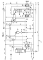
- the FIG. 1 shows a simplified circuit diagram of the device 2 according to the invention with three to a cooling circuit of the cooling water KW coupled heat pump circuits 5,15,25.
- a reservoir 14 (not shown in detail) is fed with an evaporator feed pump 21 boric acid reactor coolant RK in the device 2, wherein the reactor coolant RK is separated into the reusable constituents deionized as coolant K and neutron absorber in the form of concentrated boric acid solution NA.
- the fed reactor coolant RK is warmed up from the temperature in the storage container, for example 20 ° C ambient temperature, to about 40 ° C.
- part of the vaporized coolant KD leaving the boric acid column 3 at 50 ° C.
- the preheated reactor coolant RK is then introduced into the sump 20 of the boric acid column 3, where it mixes with the boric acid solution NA there with, for example, 7000 ppm boron (boiling state at 50 ° C., 0.125 bar).
- the contents of the sump 20 of the boric acid column 3 circulates, driven by natural convection, between the sump 20 of the boric acid column 3 and the heat exchanger 39 of the closed heat pump cycle 5 of a refrigerant KM, wherein a part of the reactor coolant RK evaporates due to the heating of the boric acid column 3.
- the refrigerant KM of the closed heat pump cycle 5 does not come into direct contact with the reactor coolant RK or the neutron absorber NA, but merely outputs the stored heat energy to the boric acid column 3 in the heat exchanger 39.
- the amount of evaporated refrigerant KD is determined by the heat output of the heat pump cycle 5.
- this heating power can be 6600 kW, which means that an evaporation rate of 2.71 kg / s is possible.
- the reactor coolant RK most of the boric acid as neutron absorber NA remains concentrated in the bottom 20 of the boric acid column 3 (concentration about 7000 ppm boron).
- the exit of the smaller proportion of the neutron absorber NA with the coolant vapor KD from the sump 20 of the boric acid column 3 takes place in accordance with the concentration and pressure-dependent distribution coefficient, for example at 10 ppm.
- the coolant vapor KD is passed from bottom to top through the boric acid column 3.
- the coolant vapor KD occurs when passing through each floor of the Borklarekolonne 3 in intensive mass transfer with the boiling coolant located on the bottom K, the concentration of the neutron NA gradually decreases further and reaches a concentration of less than 2 ppm at the end.
- a reflux stream of, for example, 0.4 kg / s of the recovered deionized K is fed in at the top of the boric acid column 3, which is branched off from the condensate pump 23 on the pressure side.
- the coolant vapor KD emerging at the top of the boric acid column 3 is passed through the recuperative preheater 22, where part of the heat energy contained is transferred to the fed-in reactor coolant RK for preheating.
- the refrigerant vapor KD continues to flow into a condenser 24. In the condenser 24, the refrigerant vapor KD is almost completely condensed, but not supercooled.
- a small residual quantity of the coolant vapor KD is passed on in a gas cooler 26, in which the remaining coolant vapor KD is precipitated by further cooling.
- the condensate from the gas cooler 26 and from the condenser 24 is collected as coolant K in a condensate tank 27, while non-condensable gases GAS are drawn off with a vacuum pump 6 from the gas cooler 26 and passed on to an exhaust system 35 become.
- the condensate collected in the condensate tank 27 is the desired refrigerant, deionized K.
- the deionized K is pumped with a condensate pump 28 into a deionized storage tank 17, where it is kept ready for reuse in the reactor cooling circuit.
- cooling water KW heats up from the temperature of the intermediate cooling water system 16 of, for example, 36 ° C. by the absorption of the condensation heat in the condenser 24 and in the gas cooler 26 to, for example, 46 ° C. and is combined in a cooling water collector 7.
- a cooling water circulation pump 12 With a cooling water circulation pump 12, the cooling water KW is conveyed from the cooling water collector 7 via a return manifold 8 via the heat exchanger 38 back to a flow distributor 9.
- the heat exchanger 38 is part of the heat pump cycle 5, which also includes the heat exchanger 39, the compressor 37 and the throttle 40.
- FIG. 4 a graphically simplified circuit diagram of the heat pump cycle 5 is shown.
- the heat pump cycle 5 is again enlarged and selected in more detail, with the secondary side only the line connections to the two heat exchangers 38 and 39, but not their interconnection with the coolant circuit and the evaporator circuit of the separator 3 are shown.
- the cooling water KW releases the heat energy previously absorbed in the condenser 24 and / or in the gas cooler 26 on the primary side of the heat exchanger 38 to the refrigerant KM within the heat pump cycle 5.
- the coolant K circulating between the sump 20 of the boric acid column 3 and the heat exchanger 39 is further warmed up and vaporized and returned to the boric acid column 3 as the coolant / coolant vapor mixture K / KD.
- the cooling water KW is cooled by the heat output in the heat exchanger 38 from the higher temperature (46 ° C) to the temperature (36 ° C) of the intermediate cooling water system 16 from.
- the cooling water KW is then supplied from the flow distributor 9 again to the condenser 24 and the gas cooler 26 for the condensation / cooling of the refrigerant vapor KD from the boric acid column 3.
- a small amount of cooling water KW constantly flows from the intermediate cooling water system 16 of the power plant via the flow distributor 9 to the above described cooling water circuit to.
- the same amount of cooling water is discharged from the return manifold 8 back into the intermediate cooling water system 16 at a correspondingly elevated temperature.
- a cooling water control valve 19 to Adjustment of this cooling water flow is a cooling water control valve 19. The heat energy dissipated in this way is lower than the electric power of the compressor 37 of the heat pump cycle 5, which is supplied to the device 2 as usable heat energy.
- the difference between the electrically supplied usable heat energy and the heat energy dissipated with the cooling water KW corresponds to the heating of the coolant K and the heating of the concentrated boronic acid solution as neutron absorber NA in the storage tanks 17, 18 relative to the temperature of the supplied boric acid-containing reactor coolant RK from the reactor coolant storage tank 14.
- the refrigerant KM is vaporized by means of the thermal energy absorbed from the cycle of cooling water KW and further compressed under temperature increase by the compressor 37, so that the refrigerant vapor KMD the heat energy through the heat exchanger 39 back to the circulating, boiling, concentrated boric acid solution in the sump 20 of the boric acid column 3 transfers.
- the compressor 37 is a hermetically sealed, electrically driven compressor heat pump.
- the refrigerant KM preferably tetrafluoroethane, is evaporated at a constant temperature by the heat energy transferred from the cooling water KW.
- the evaporated refrigerant KMD is condensed on the primary side and at the same time, on the secondary side, the boron-containing reactor coolant K conducted in the evaporator circuit 36 is vaporized.
- the evaporated refrigerant KMD is possibly slightly overheated.
- the compressor 37 of the heat pump circuit 5 sucks the refrigerant vapor KMD generated in the evaporator, compresses it with an increase in temperature and conveys the evaporated refrigerant KMD into the condenser of the heat pump cycle 5, ie into the heat exchanger 39.
- the vaporized refrigerant KMD is overheated.
- the vaporized refrigerant KMD gives by cooling to saturation state heat energy for heating the boric acid solution as a neutron absorber NA in the bottom 20 of the boric acid 3 from.
- the heat is released by condensation of the evaporated refrigerant KMD at a constant temperature and subsequent slight supercooling of the liquid refrigerant KM.
- the heat pump cycle is completed by the refrigerant KM flows through a throttle 40 in the evaporator, that is, in the heat exchanger 38, the heat pump cycle 5.
- the temperature of the refrigerant KM decreases to such an extent that thermal energy is taken up again from the cooling water KW in the evaporator of the heat pump cycle 5, that is to say in the heat exchanger 38.
- the fed coolant K from the condensate tank 27 has a temperature of nearly 50 ° C and is therefore in the boiling state when it trickles down through the packed packing in the Entgaserkolonne 30 by gravity from top to bottom.
- To the sump 29 of the degasifier column 30 is connected via an evaporator circuit 36 'a secondary side connected in a heat pump circuit 15 heat exchanger 39', which evaporates a portion of the collected in the sump 29 degassed refrigerant K by supplying heat from the closed heat pump circuit 15.
- the vaporized in the sump 29 part of the coolant K corresponds to about 3% to 5% of the coolant throughput through the Entgaserstrom 30.
- the generated refrigerant KD rises through the Entgaserkolonne 30 and occurs in the Gear Sciencespackung 31 in intensive mass transfer with the trickling down coolant K, whereby the desired degassing effect occurs.
- the coolant vapor KD emerging at the top of the degasser column 30 passes into a reflux condenser 32. In the reflux condenser 32 it is almost completely condensed and only very slightly undercooled, if at all. A small residual amount of the coolant vapor KD is forwarded to a gas cooler 33, wherein the remaining coolant vapor KD is precipitated in the gas cooler 33 by further cooling.
- the condensate from the gas cooler 33 and from the reflux condenser 32 passes by gravity back into the head of Entgaserkolonne 30, while non-condensable gases GAS are withdrawn with the vacuum pump 6 from the gas cooler 33 and forwarded to the exhaust system 35.
- cooling water KW is conducted out of the intermediate cooling water system 16 of the nuclear installation 1 by the return condenser 32 and the gas cooler 33.
- the cooling water KW heats up, for example, from 36 ° C to 46 ° C.
- the degassed coolant K collected in the sump 29 of the degasifier column 30 is discharged into a corresponding degassing pump 34 with a degassing pump 34. not shown, from where it is released after appropriate control of the nuclear facility 1.
- the heat energy required for the partial evaporation of the degasified cooling water K is provided by the heat pump circuit 15, which in turn uses the cooling water KW as a heat source, which exits the return condenser 32 and the gas cooler 33 at a temperature of for example 46 ° C. and is combined in the cooling water collector 7 , As in the case of the boric acid evaporator system 3 described above, a closed cooling water circuit is operated with the cooling water circulation pump 12, with which the heat energy exiting the degasser column 30 with the coolant vapor KD at the top of the column is transported to the heat pump circuit 15 at the bottom 29 of the degasifier column 30.
- the cooling water circuit is constantly running a small amount of cooling water KW from the intermediate cooling water system 16 of the nuclear installation 1 via the flow distributor 9 , The same amount of cooling water KW is discharged from the return manifold 8 back into the intermediate cooling water system 16 at a correspondingly elevated temperature.
- the control valve 19 The heat energy dissipated in this way corresponds to the electrical power of the compressor 37 'of the second heat pump cycle 15th
- the closed heat pump circuit 15 functions the same as the closed heat pump circuit 5 belonging to the boric acid evaporator system 3.
- the temperatures, pressures and consequently the delivery number ⁇ are preferably the same as in the first heat pump circuit 5.
- the required electric power is due to the smaller amount of coolant K to be evaporated much smaller.
- Coolant K applied for the cooling system. If the coolant balance of the nuclear installation 1 has to be supplemented, the new coolant K is taken from a deionized distribution system. The provided coolant K is normally not free of oxygen and must therefore be degassed before use. This is done in the above described Entgaserkolonne 30.
- the coolant K from the Deionatver Minorssystem example has an average ambient temperature of 20 ° C and therefore, before it can be fed into the Entgaserkolonne 30, to the process temperature of 50 ° C - in the case of pressure of 0.125 bar absolute - preheated.
- the third heat pump circuit 25 uses the cooling water KW as the heat source, which flows from the flow distributor 9 via the condenser 24, the gas cooler 26, the return condenser 32 and the gas cooler 33 are led to the cooling water collector 7 and then with the cooling water circulation pump 12 via the return manifold 8 and the refrigerant evaporator (heat exchanger 38 ") of the third heat pump cycle 25 is conveyed back to the flow distributor 9.
- the heat exchanger 38 "initially takes on the heat energy not absorbed by the simultaneously running heat exchanger 38 'of the degasifier column 30 from the reflux condenser 32 and the gas cooler 33.
- the vacuum boric acid evaporator system 3 according to the invention and degassing plant 30 with heat recovery through closed heat pump circuits is operated almost fully automatically with the aid of corresponding electrical and control equipment.
- the process control devices include measuring points for detecting the state variables, such as the reactor coolant RK, the coolant K or the cooling water KW in the individual system sections.
- the control circuits are used for continuous monitoring and adjustment of individual parameters to predetermined setpoints, such as the control for the stepwise sequence when starting the separating device 2 from standstill to stationary operation and when moving from stationary operation to standstill.
- the closed circuits of the heat pumps 5, 15, 55 are made respectively the main components evaporator, compressor, condenser and a throttle. These together form a single-stage closed heat pump cycle, wherein the refrigerant KM circulating in the heat pump cycle does not come into contact with the reactor coolant RK or the neutron absorber NA in the sump 20, 29 of the separators 3, 30.
- the heat exchangers in the heat pumps 5, 15, 25 are preferably designed as a shell-and-tube heat exchanger, for example in the customary chillers. Since the condenser in the boric acid column 3 on the process side contains radioactive reactor coolant RK, the condenser of the first heat pump 5 is arranged separately from the other components for radiation protection reasons.
- a hermetic or semi-hermetic design is particularly advantageous, since in this case the heat loss of the drive motor can be used directly as process heat and thus the maximum possible delivery number ⁇ is achieved.
- turbo compressors and screw compressors are available with this particularly favorable, hermetic or semi-hermetic design. They also offer the advantage that the lubrication integrated into the closed unit of the heat exchanger or lubrication is not required for contactless storage.
- the hermetic or semi-hermetic compressors and compressors with external water-cooled drive machines are well integrated into the system, since even in these the engine waste heat through the heat pumps 5, 15, 25 and the circuits of the refrigerant KM can be used for the inventive method as a heat source.
- the vacuum pump 6 to lower the pressure in the columns 3, 30 and in the evaporators of the closed heat pump circuits is preferably designed as a water ring compressor in the form of a canned machine or magnetically coupled to the external drive motor compressor.
- the setting of the pressure to 0.125 bar and thus to a process temperature of 50 ° C has significant advantages.
- the reactor coolant RK to be separated is fed from the storage containers to the boric acid column 3 at a temperature which, depending on the duration of the storage period, is between 20 ° C. and 50 ° C. At a process temperature of 50 ° C, therefore, only a slight warming of the water is required to reach the boiling state.
- deionized as coolant K and boric acid solution as neutron absorber NA In order for the products obtained in the separation process, deionized as coolant K and boric acid solution as neutron absorber NA, to be fed back into the reactor cooling circuit if required, they must have a temperature of about 50 ° C. If the temperature of the separation process is already 50 ° C, further cooling is no longer necessary.
- a temperature level of about 30 to 50 ° C on the heat source side and of almost 50 ° C on the heat consumer side is particularly advantageous, because thereby the use of an easy-to-use and efficient refrigerant KM , such as tetrafluoroethane, in the closed non-radioactive heat pump cycle is possible.
- the low temperature difference between the heat source and heat utilization side also results in a high efficiency and thus a low electrical power to be expended.
- FIG. 2 shows a simplified circuit diagram of the device 2 according to the invention with the respective thermodynamic state values for the evaporation of borated water (reactor coolant RK) with 2200 ppm boron as neutron absorber NA.
- the device 2 In the stationary operating state, the device 2 has a pressure of 0.125 bar absolute and the process temperature is therefore set to 50 ° C.
- the heat pump cycle 5 at the Borklakla 3 requires an electrical power of about 1100 kW.
- the reactor coolant RK is passed from a reactor coolant reservoir 14 via the recuperative preheater 22 into the boric acid column 2. in the recuperative preheater 22, the fed reactor coolant RK is warmed from the temperature in the storage container, for example 20 ° C, to about 40 ° C. For heating, part of the coolant vapor KD leaving the boric acid column 3 at 50 ° C. is used.
- the preheated reactor coolant RK is subsequently introduced into the sump 20 of the boric acid column 3, where it mixes with the boric acid solution NA present there.
- the content of the sump 20 of the boric acid column 3 circulates, driven by the heat supply from the closed heat pump cycle 5.
- the amount of the refrigerant KD vaporized in the Borcicekolonne is determined by the heat output of the heat pump cycle 5.
- the refrigerant KM or the evaporated refrigerant KMD within the closed heat pump cycle 5 are indicated by the identical short designations.
- the heat transfer from the heat pump circuit 5 to the bottom circuit 36 of the boric acid column 3 takes place in the condenser 39 designed as a recuperator.
- the refrigerant KM or the refrigerant vapor KMD of the exemplary embodiment of FIG FIG. 2 unused heat pump circuits 15, 25 are not shown.
- the cycle of the cooling water KW is in thermal contact with the heat exchanger 38, the condenser 24 and the gas cooler 26 and is operated via the flow distributor 9, the cooling water collector 7, the cooling water circulation pump 12 and the return distributor 8. A small part of the throughput is exchanged via the flow or the return of the intermediate cooling system 16 with this.
- FIG. 3 shows a simplified circuit diagram of the device 2 according to the invention with the respective thermodynamic state values for the degassing of oxygen-rich deionized as coolant K.
- the intermediate cooling water system 16 is used as a heat source for taking place in the heat pump 25 preheating the oxygen-containing coolant K.
- the refrigerant KM or the evaporated refrigerant KMD are indicated by the corresponding abbreviations within the heat pump circuits 15 and 25, respectively.
- the heat transfer from the intermediate cooling water circuit to the heat pump circuit 15 or 25 takes place in the evaporator 38 'or 38 "designed as a recuperator.
- the refrigerant KM and the refrigerant steam KMD of the exemplary embodiment of FIG FIG. 3 unused heat pump cycle 5 are not shown.
- the oxygen-containing coolant K required in particular to supplement the reactor coolant RK is degassed in the degasifier column 30. From the temperature of the Deionatver Minorssystem (20 ° C), the oxygen-containing coolant K must be preheated to the process temperature of 50 ° C prior to feeding into the Entgaserkolonne 30. This is done by means of the third heat pump 25, the condenser transfers the required heat energy to the fresh deionized K.
- the third heat pump 25 uses as a heat source, the cooling water KW, which led from the flow distributor 9 via the condenser 24, the gas cooler 26, the reflux condenser 32 to the cooling water collector 7 and then with the cooling water circulation pump 12 via the return manifold 8 and the evaporator of the third heat pump 25 is conveyed back to the flow distributor 9.
- the heat exchanger 38 "initially takes up the heat energy not absorbed by the simultaneously running heat exchanger 38 'of the degasifier column 30 from the reflux condenser 32 and the gas cooler 33.
- the control valve 19 is closed and a corresponding amount of the cooling water KW from the heated Eisenkühlementsystem 16 of the nuclear installation 1 to the cooling water collector 7 via a second cooling water control valve 10.
- the corresponding amount of in the heat exchangers 38 'and 38 " cooled cooling water KW is discharged via the flow distributor 9 in the cooling water supply at a temperature of 46 ° C in the intermediate cooling water system 16 of the nuclear facility 1.
Landscapes
- Physics & Mathematics (AREA)
- Engineering & Computer Science (AREA)
- Plasma & Fusion (AREA)
- General Engineering & Computer Science (AREA)
- High Energy & Nuclear Physics (AREA)
- Chemical & Material Sciences (AREA)
- Chemical Kinetics & Catalysis (AREA)
- Structure Of Emergency Protection For Nuclear Reactors (AREA)
- Monitoring And Testing Of Nuclear Reactors (AREA)
Applications Claiming Priority (1)
| Application Number | Priority Date | Filing Date | Title |
|---|---|---|---|
| DE102008013933A DE102008013933A1 (de) | 2008-03-12 | 2008-03-12 | Verfahren und Vorrichtung zum Abtrennen eines Neutronenabsorbers von einem Kühlmittel eines Kühlkreislaufes |
Publications (3)
| Publication Number | Publication Date |
|---|---|
| EP2109114A2 true EP2109114A2 (fr) | 2009-10-14 |
| EP2109114A3 EP2109114A3 (fr) | 2010-04-21 |
| EP2109114B1 EP2109114B1 (fr) | 2017-08-23 |
Family
ID=41012981
Family Applications (1)
| Application Number | Title | Priority Date | Filing Date |
|---|---|---|---|
| EP09001376.4A Not-in-force EP2109114B1 (fr) | 2008-03-12 | 2009-02-02 | Procédé de séparation d'un absorbeur de neutrons et d'un liquide caloporteur utilisé dans un circuit de refroidissement |
Country Status (5)
| Country | Link |
|---|---|
| EP (1) | EP2109114B1 (fr) |
| JP (1) | JP5465899B2 (fr) |
| CN (1) | CN101533681B (fr) |
| BR (1) | BRPI0900899B1 (fr) |
| DE (1) | DE102008013933A1 (fr) |
Cited By (5)
| Publication number | Priority date | Publication date | Assignee | Title |
|---|---|---|---|---|
| DE102011012810A1 (de) * | 2011-03-02 | 2012-09-06 | Oerlikon Leybold Vacuum Gmbh | Verfahren zur Konfiguration einer Vakuum-Pumpenanlage |
| CN103405945A (zh) * | 2013-07-31 | 2013-11-27 | 中科华核电技术研究院有限公司 | 脱除核电站反应堆冷却剂中溶解气体的脱气装置及其方法 |
| EP2860482A3 (fr) * | 2009-12-11 | 2015-04-22 | SKC Co., Ltd. | Système de récupération de la chaleur des déchets |
| WO2020244762A1 (fr) | 2019-06-06 | 2020-12-10 | Framatome Gmbh | Système de dégazage pour centrale nucléaire et procédé de dégazage d'un flux de fluide de refroidissement de réacteur |
| CN113842659A (zh) * | 2021-11-29 | 2021-12-28 | 东营威联化学有限公司 | 一种节能型二甲苯生产用分馏装置 |
Families Citing this family (5)
| Publication number | Priority date | Publication date | Assignee | Title |
|---|---|---|---|---|
| CN107680703A (zh) * | 2017-11-08 | 2018-02-09 | 上海核工程研究设计院有限公司 | 一种核电站放射性废液系统的脱气子系统 |
| CN109961865B (zh) * | 2017-12-22 | 2024-02-13 | 中核核电运行管理有限公司 | 一种核电站制硼预热加热装置 |
| CN108711459B (zh) * | 2018-05-30 | 2020-12-11 | 中国原子能科学研究院 | 一种用于快堆的多样化保护装置 |
| CN111389039B (zh) * | 2020-03-18 | 2023-07-07 | 谢海刚 | 一种精馏热能闭式循环节能系统 |
| CN115420605B (zh) * | 2022-09-15 | 2024-07-30 | 中国石油大学(华东) | 一种氯离子在两侧有温差的混凝土中传输实验装置及方法 |
Citations (1)
| Publication number | Priority date | Publication date | Assignee | Title |
|---|---|---|---|---|
| DE19833739C1 (de) | 1998-07-27 | 2000-03-30 | Siemens Ag | Verfahren und Vorrichtung zum Abtrennen eines neutronenabsorbierenden Absorbers von einem Kühlmittel |
Family Cites Families (11)
| Publication number | Priority date | Publication date | Assignee | Title |
|---|---|---|---|---|
| DE1114168B (de) * | 1960-08-03 | 1961-09-28 | Bayer Ag | Destillationsvorrichtung mit Waermepumpe |
| DE2312228A1 (de) * | 1973-03-12 | 1974-09-26 | Siemens Ag | Druckwasserreaktor |
| US4350571A (en) * | 1980-10-10 | 1982-09-21 | Erickson Donald C | Absorption heat pump augmented thermal separation process |
| JPS618699A (ja) * | 1984-06-22 | 1986-01-16 | 株式会社神戸製鋼所 | ホウ酸ソ−ダ廃液の処理方法 |
| US5294303A (en) * | 1992-12-08 | 1994-03-15 | The Dow Chemical Company | Method for removing dissolved immiscible organics from am aqueous medium at ambient temperatures |
| JP2844296B2 (ja) * | 1993-06-29 | 1999-01-06 | 正樹 佐久間 | 真空濃縮装置 |
| JPH08297196A (ja) * | 1995-04-27 | 1996-11-12 | Hitachi Ltd | 沸騰水型原子力プラント |
| JP3448201B2 (ja) * | 1998-01-28 | 2003-09-22 | 三菱重工業株式会社 | 排水の蒸発濃縮装置 |
| US20030057165A1 (en) * | 2001-09-25 | 2003-03-27 | Carson Thomas Powell | Process for the separation of a liquid or liquids from another liquid or liquids, or from a solid or mixture of solids, with the minimum energy required for separation and recovery and recovered for re-use within the process |
| FR2840542B1 (fr) * | 2002-06-07 | 2005-03-18 | Andre Champeau | Distillateur d'effluents liquides, aqueux ou organiques a regeneration |
| DE102006055966A1 (de) * | 2006-11-24 | 2008-05-29 | Areva Np Gmbh | Kerntechnische Anlage und Verfahren zum Betreiben einer kerntechnischen Anlage |
-
2008
- 2008-03-12 DE DE102008013933A patent/DE102008013933A1/de not_active Ceased
-
2009
- 2009-02-02 EP EP09001376.4A patent/EP2109114B1/fr not_active Not-in-force
- 2009-03-11 BR BRPI0900899-3A patent/BRPI0900899B1/pt not_active IP Right Cessation
- 2009-03-11 JP JP2009058521A patent/JP5465899B2/ja not_active Expired - Fee Related
- 2009-03-12 CN CN2009101271300A patent/CN101533681B/zh not_active Expired - Fee Related
Patent Citations (1)
| Publication number | Priority date | Publication date | Assignee | Title |
|---|---|---|---|---|
| DE19833739C1 (de) | 1998-07-27 | 2000-03-30 | Siemens Ag | Verfahren und Vorrichtung zum Abtrennen eines neutronenabsorbierenden Absorbers von einem Kühlmittel |
Cited By (8)
| Publication number | Priority date | Publication date | Assignee | Title |
|---|---|---|---|---|
| EP2860482A3 (fr) * | 2009-12-11 | 2015-04-22 | SKC Co., Ltd. | Système de récupération de la chaleur des déchets |
| US9574829B2 (en) | 2009-12-11 | 2017-02-21 | Skc Co., Ltd. | System for recovering waste heat |
| DE102011012810A1 (de) * | 2011-03-02 | 2012-09-06 | Oerlikon Leybold Vacuum Gmbh | Verfahren zur Konfiguration einer Vakuum-Pumpenanlage |
| CN103405945A (zh) * | 2013-07-31 | 2013-11-27 | 中科华核电技术研究院有限公司 | 脱除核电站反应堆冷却剂中溶解气体的脱气装置及其方法 |
| CN103405945B (zh) * | 2013-07-31 | 2016-02-10 | 中科华核电技术研究院有限公司 | 脱除核电站反应堆冷却剂中溶解气体的脱气装置及其方法 |
| WO2020244762A1 (fr) | 2019-06-06 | 2020-12-10 | Framatome Gmbh | Système de dégazage pour centrale nucléaire et procédé de dégazage d'un flux de fluide de refroidissement de réacteur |
| US12106863B2 (en) | 2019-06-06 | 2024-10-01 | Framatome Gmbh | Degasification system for a nuclear power plant and method for degassing a flow of reactor coolant |
| CN113842659A (zh) * | 2021-11-29 | 2021-12-28 | 东营威联化学有限公司 | 一种节能型二甲苯生产用分馏装置 |
Also Published As
| Publication number | Publication date |
|---|---|
| BRPI0900899A2 (pt) | 2010-01-26 |
| EP2109114B1 (fr) | 2017-08-23 |
| DE102008013933A1 (de) | 2009-11-05 |
| CN101533681A (zh) | 2009-09-16 |
| BRPI0900899B1 (pt) | 2019-04-09 |
| EP2109114A3 (fr) | 2010-04-21 |
| JP5465899B2 (ja) | 2014-04-09 |
| JP2009216708A (ja) | 2009-09-24 |
| CN101533681B (zh) | 2013-06-12 |
Similar Documents
| Publication | Publication Date | Title |
|---|---|---|
| EP2109114B1 (fr) | Procédé de séparation d'un absorbeur de neutrons et d'un liquide caloporteur utilisé dans un circuit de refroidissement | |
| EP2095370B1 (fr) | Installation technique nucléaire et procédé d'utilisation d'une installation technique nucléaire | |
| DE2754626C2 (de) | Mit einer Energiequelle relativ niedriger Temperatur, insbesondere Solarenergie, arbeitende Kälteanlage | |
| DE60315823T2 (de) | Verfahren und einrichtung zur stromerzeugung aus der im kern mindestens eines hochtemperatur-kernreaktors erzeugten wärme | |
| EP0042160A2 (fr) | Procédé et installation pour emmagasiner la chaleur et pour en élever la température | |
| EP3111058B1 (fr) | Procédé et dispositif de stockage d'énergie dans une solution alcaline | |
| WO2014020091A1 (fr) | Système de dissipation de chaleur pour installation nucléaire | |
| EP2464603B1 (fr) | Procédé et dispositif de désalinisation de l'eau de mer | |
| EP2232019B1 (fr) | Procédé, dispositif et système d'application d'énergie à un fluide | |
| DE102013210425A1 (de) | Anlage und Verfahren zum Aufbereiten von Wasser | |
| EP1870646A2 (fr) | Procédé et dispositif destinés à la récupération de chaleur de condensation à partir d'un cycle thermodynamique | |
| DE102016101292A1 (de) | Kühlvorrichtung für eine elektrische Antriebseinheit eines Fahrzeugs | |
| DE102017008253B3 (de) | Sicherheitsbehälterkühlsystem | |
| DE102012007210B4 (de) | Verfahren und Vorrichtung zur thermischen Speicherung von Elektroenergie | |
| DE2538730C2 (de) | Verfahren zur Kälteerzeugung mittels eines Kompressions-Absorptions-Kreisprozesses und Anlage zur Durchführung des Verfahrens | |
| DE19833739C1 (de) | Verfahren und Vorrichtung zum Abtrennen eines neutronenabsorbierenden Absorbers von einem Kühlmittel | |
| DE3004197A1 (de) | Verfahren zu rueckgewinnen von waermeenergie, die in den brueden von fuer thermische stofftrennprozesse eingesetzten mehrstufenverdampfern enthalten ist, und vorrichtung zur durchfuehrung des verfahrens | |
| EP3058289A1 (fr) | Machine frigorifique à absorption | |
| DE102020113506B3 (de) | Kältespeicheranlage und Speicherkühlverfahren | |
| DE102013221129A1 (de) | Wärmespeichervorrichtung und Verfahren zum Speichern von Wärme | |
| DE4435862C1 (de) | Verfahren und Vorrichtung zum Abkühlen, insbesondere zum Abschrecken, von Werkstücken durch Gase | |
| DE617648C (de) | Thermodynamisches Verfahren zur Aufspeicherung von Energie | |
| DE102012020480A1 (de) | Verfahren zum Betreiben eines solarthermischen Kraftwerks sowie solarthermisches Kraftwerk | |
| EP3467377A1 (fr) | Installation à flammes perdues pour la production d'eau chaude et procédé de fonctionnement d'une installation à flammes perdues pour la production d'eau chaude | |
| DE102023208569A1 (de) | Dampfspeicherkraftwerk und Verfahren zum Betreiben eines solchen |
Legal Events
| Date | Code | Title | Description |
|---|---|---|---|
| PUAI | Public reference made under article 153(3) epc to a published international application that has entered the european phase |
Free format text: ORIGINAL CODE: 0009012 |
|
| AK | Designated contracting states |
Kind code of ref document: A2 Designated state(s): AT BE BG CH CY CZ DE DK EE ES FI FR GB GR HR HU IE IS IT LI LT LU LV MC MK MT NL NO PL PT RO SE SI SK TR |
|
| AX | Request for extension of the european patent |
Extension state: AL BA RS |
|
| PUAL | Search report despatched |
Free format text: ORIGINAL CODE: 0009013 |
|
| AK | Designated contracting states |
Kind code of ref document: A3 Designated state(s): AT BE BG CH CY CZ DE DK EE ES FI FR GB GR HR HU IE IS IT LI LT LU LV MC MK MT NL NO PL PT RO SE SI SK TR |
|
| AX | Request for extension of the european patent |
Extension state: AL BA RS |
|
| RIC1 | Information provided on ipc code assigned before grant |
Ipc: C02F 1/04 20060101ALI20100315BHEP Ipc: B01D 3/00 20060101ALI20100315BHEP Ipc: G21C 19/307 20060101AFI20090904BHEP |
|
| 17P | Request for examination filed |
Effective date: 20100820 |
|
| 17Q | First examination report despatched |
Effective date: 20100917 |
|
| AKX | Designation fees paid |
Designated state(s): AT BE BG CH CY CZ DE DK EE ES FI FR GB GR HR HU IE IS IT LI LT LU LV MC MK MT NL NO PL PT RO SE SI SK TR |
|
| RAP1 | Party data changed (applicant data changed or rights of an application transferred) |
Owner name: AREVA GMBH |
|
| GRAP | Despatch of communication of intention to grant a patent |
Free format text: ORIGINAL CODE: EPIDOSNIGR1 |
|
| STAA | Information on the status of an ep patent application or granted ep patent |
Free format text: STATUS: GRANT OF PATENT IS INTENDED |
|
| INTG | Intention to grant announced |
Effective date: 20170320 |
|
| GRAS | Grant fee paid |
Free format text: ORIGINAL CODE: EPIDOSNIGR3 |
|
| GRAA | (expected) grant |
Free format text: ORIGINAL CODE: 0009210 |
|
| STAA | Information on the status of an ep patent application or granted ep patent |
Free format text: STATUS: THE PATENT HAS BEEN GRANTED |
|
| AK | Designated contracting states |
Kind code of ref document: B1 Designated state(s): AT BE BG CH CY CZ DE DK EE ES FI FR GB GR HR HU IE IS IT LI LT LU LV MC MK MT NL NO PL PT RO SE SI SK TR |
|
| REG | Reference to a national code |
Ref country code: GB Ref legal event code: FG4D Free format text: NOT ENGLISH |
|
| REG | Reference to a national code |
Ref country code: CH Ref legal event code: EP |
|
| REG | Reference to a national code |
Ref country code: AT Ref legal event code: REF Ref document number: 922151 Country of ref document: AT Kind code of ref document: T Effective date: 20170915 |
|
| REG | Reference to a national code |
Ref country code: IE Ref legal event code: FG4D Free format text: LANGUAGE OF EP DOCUMENT: GERMAN |
|
| REG | Reference to a national code |
Ref country code: DE Ref legal event code: R096 Ref document number: 502009014287 Country of ref document: DE |
|
| REG | Reference to a national code |
Ref country code: NL Ref legal event code: MP Effective date: 20170823 |
|
| REG | Reference to a national code |
Ref country code: LT Ref legal event code: MG4D |
|
| PG25 | Lapsed in a contracting state [announced via postgrant information from national office to epo] |
Ref country code: HR Free format text: LAPSE BECAUSE OF FAILURE TO SUBMIT A TRANSLATION OF THE DESCRIPTION OR TO PAY THE FEE WITHIN THE PRESCRIBED TIME-LIMIT Effective date: 20170823 Ref country code: LT Free format text: LAPSE BECAUSE OF FAILURE TO SUBMIT A TRANSLATION OF THE DESCRIPTION OR TO PAY THE FEE WITHIN THE PRESCRIBED TIME-LIMIT Effective date: 20170823 Ref country code: SE Free format text: LAPSE BECAUSE OF FAILURE TO SUBMIT A TRANSLATION OF THE DESCRIPTION OR TO PAY THE FEE WITHIN THE PRESCRIBED TIME-LIMIT Effective date: 20170823 Ref country code: NO Free format text: LAPSE BECAUSE OF FAILURE TO SUBMIT A TRANSLATION OF THE DESCRIPTION OR TO PAY THE FEE WITHIN THE PRESCRIBED TIME-LIMIT Effective date: 20171123 Ref country code: NL Free format text: LAPSE BECAUSE OF FAILURE TO SUBMIT A TRANSLATION OF THE DESCRIPTION OR TO PAY THE FEE WITHIN THE PRESCRIBED TIME-LIMIT Effective date: 20170823 |
|
| REG | Reference to a national code |
Ref country code: FR Ref legal event code: PLFP Year of fee payment: 10 |
|
| PG25 | Lapsed in a contracting state [announced via postgrant information from national office to epo] |
Ref country code: IS Free format text: LAPSE BECAUSE OF FAILURE TO SUBMIT A TRANSLATION OF THE DESCRIPTION OR TO PAY THE FEE WITHIN THE PRESCRIBED TIME-LIMIT Effective date: 20171223 Ref country code: LV Free format text: LAPSE BECAUSE OF FAILURE TO SUBMIT A TRANSLATION OF THE DESCRIPTION OR TO PAY THE FEE WITHIN THE PRESCRIBED TIME-LIMIT Effective date: 20170823 Ref country code: BG Free format text: LAPSE BECAUSE OF FAILURE TO SUBMIT A TRANSLATION OF THE DESCRIPTION OR TO PAY THE FEE WITHIN THE PRESCRIBED TIME-LIMIT Effective date: 20171123 Ref country code: ES Free format text: LAPSE BECAUSE OF FAILURE TO SUBMIT A TRANSLATION OF THE DESCRIPTION OR TO PAY THE FEE WITHIN THE PRESCRIBED TIME-LIMIT Effective date: 20170823 Ref country code: PL Free format text: LAPSE BECAUSE OF FAILURE TO SUBMIT A TRANSLATION OF THE DESCRIPTION OR TO PAY THE FEE WITHIN THE PRESCRIBED TIME-LIMIT Effective date: 20170823 Ref country code: GR Free format text: LAPSE BECAUSE OF FAILURE TO SUBMIT A TRANSLATION OF THE DESCRIPTION OR TO PAY THE FEE WITHIN THE PRESCRIBED TIME-LIMIT Effective date: 20171124 |
|
| PG25 | Lapsed in a contracting state [announced via postgrant information from national office to epo] |
Ref country code: DK Free format text: LAPSE BECAUSE OF FAILURE TO SUBMIT A TRANSLATION OF THE DESCRIPTION OR TO PAY THE FEE WITHIN THE PRESCRIBED TIME-LIMIT Effective date: 20170823 Ref country code: RO Free format text: LAPSE BECAUSE OF FAILURE TO SUBMIT A TRANSLATION OF THE DESCRIPTION OR TO PAY THE FEE WITHIN THE PRESCRIBED TIME-LIMIT Effective date: 20170823 Ref country code: CZ Free format text: LAPSE BECAUSE OF FAILURE TO SUBMIT A TRANSLATION OF THE DESCRIPTION OR TO PAY THE FEE WITHIN THE PRESCRIBED TIME-LIMIT Effective date: 20170823 |
|
| REG | Reference to a national code |
Ref country code: DE Ref legal event code: R097 Ref document number: 502009014287 Country of ref document: DE |
|
| PG25 | Lapsed in a contracting state [announced via postgrant information from national office to epo] |
Ref country code: SK Free format text: LAPSE BECAUSE OF FAILURE TO SUBMIT A TRANSLATION OF THE DESCRIPTION OR TO PAY THE FEE WITHIN THE PRESCRIBED TIME-LIMIT Effective date: 20170823 Ref country code: IT Free format text: LAPSE BECAUSE OF FAILURE TO SUBMIT A TRANSLATION OF THE DESCRIPTION OR TO PAY THE FEE WITHIN THE PRESCRIBED TIME-LIMIT Effective date: 20170823 Ref country code: EE Free format text: LAPSE BECAUSE OF FAILURE TO SUBMIT A TRANSLATION OF THE DESCRIPTION OR TO PAY THE FEE WITHIN THE PRESCRIBED TIME-LIMIT Effective date: 20170823 |
|
| PLBE | No opposition filed within time limit |
Free format text: ORIGINAL CODE: 0009261 |
|
| STAA | Information on the status of an ep patent application or granted ep patent |
Free format text: STATUS: NO OPPOSITION FILED WITHIN TIME LIMIT |
|
| 26N | No opposition filed |
Effective date: 20180524 |
|
| PG25 | Lapsed in a contracting state [announced via postgrant information from national office to epo] |
Ref country code: SI Free format text: LAPSE BECAUSE OF FAILURE TO SUBMIT A TRANSLATION OF THE DESCRIPTION OR TO PAY THE FEE WITHIN THE PRESCRIBED TIME-LIMIT Effective date: 20170823 |
|
| REG | Reference to a national code |
Ref country code: CH Ref legal event code: PL |
|
| REG | Reference to a national code |
Ref country code: DE Ref legal event code: R082 Ref document number: 502009014287 Country of ref document: DE Representative=s name: TERGAU & WALKENHORST PATENTANWAELTE PARTGMBB, DE Ref country code: DE Ref legal event code: R082 Ref document number: 502009014287 Country of ref document: DE Ref country code: DE Ref legal event code: R081 Ref document number: 502009014287 Country of ref document: DE Owner name: FRAMATOME GMBH, DE Free format text: FORMER OWNER: AREVA GMBH, 91052 ERLANGEN, DE |
|
| PG25 | Lapsed in a contracting state [announced via postgrant information from national office to epo] |
Ref country code: MT Free format text: LAPSE BECAUSE OF FAILURE TO SUBMIT A TRANSLATION OF THE DESCRIPTION OR TO PAY THE FEE WITHIN THE PRESCRIBED TIME-LIMIT Effective date: 20170823 Ref country code: MC Free format text: LAPSE BECAUSE OF FAILURE TO SUBMIT A TRANSLATION OF THE DESCRIPTION OR TO PAY THE FEE WITHIN THE PRESCRIBED TIME-LIMIT Effective date: 20170823 |
|
| REG | Reference to a national code |
Ref country code: IE Ref legal event code: MM4A |
|
| REG | Reference to a national code |
Ref country code: BE Ref legal event code: MM Effective date: 20180228 |
|
| PG25 | Lapsed in a contracting state [announced via postgrant information from national office to epo] |
Ref country code: LI Free format text: LAPSE BECAUSE OF NON-PAYMENT OF DUE FEES Effective date: 20180228 Ref country code: CH Free format text: LAPSE BECAUSE OF NON-PAYMENT OF DUE FEES Effective date: 20180228 Ref country code: LU Free format text: LAPSE BECAUSE OF NON-PAYMENT OF DUE FEES Effective date: 20180202 |
|
| PG25 | Lapsed in a contracting state [announced via postgrant information from national office to epo] |
Ref country code: IE Free format text: LAPSE BECAUSE OF NON-PAYMENT OF DUE FEES Effective date: 20180202 |
|
| PG25 | Lapsed in a contracting state [announced via postgrant information from national office to epo] |
Ref country code: BE Free format text: LAPSE BECAUSE OF NON-PAYMENT OF DUE FEES Effective date: 20180228 |
|
| REG | Reference to a national code |
Ref country code: GB Ref legal event code: 732E Free format text: REGISTERED BETWEEN 20190314 AND 20190320 |
|
| REG | Reference to a national code |
Ref country code: AT Ref legal event code: MM01 Ref document number: 922151 Country of ref document: AT Kind code of ref document: T Effective date: 20180202 |
|
| PG25 | Lapsed in a contracting state [announced via postgrant information from national office to epo] |
Ref country code: AT Free format text: LAPSE BECAUSE OF NON-PAYMENT OF DUE FEES Effective date: 20180202 |
|
| REG | Reference to a national code |
Ref country code: DE Ref legal event code: R082 Ref document number: 502009014287 Country of ref document: DE |
|
| PG25 | Lapsed in a contracting state [announced via postgrant information from national office to epo] |
Ref country code: TR Free format text: LAPSE BECAUSE OF FAILURE TO SUBMIT A TRANSLATION OF THE DESCRIPTION OR TO PAY THE FEE WITHIN THE PRESCRIBED TIME-LIMIT Effective date: 20170823 |
|
| PG25 | Lapsed in a contracting state [announced via postgrant information from national office to epo] |
Ref country code: HU Free format text: LAPSE BECAUSE OF FAILURE TO SUBMIT A TRANSLATION OF THE DESCRIPTION OR TO PAY THE FEE WITHIN THE PRESCRIBED TIME-LIMIT; INVALID AB INITIO Effective date: 20090202 Ref country code: PT Free format text: LAPSE BECAUSE OF FAILURE TO SUBMIT A TRANSLATION OF THE DESCRIPTION OR TO PAY THE FEE WITHIN THE PRESCRIBED TIME-LIMIT Effective date: 20170823 |
|
| PG25 | Lapsed in a contracting state [announced via postgrant information from national office to epo] |
Ref country code: MK Free format text: LAPSE BECAUSE OF NON-PAYMENT OF DUE FEES Effective date: 20170823 Ref country code: CY Free format text: LAPSE BECAUSE OF FAILURE TO SUBMIT A TRANSLATION OF THE DESCRIPTION OR TO PAY THE FEE WITHIN THE PRESCRIBED TIME-LIMIT Effective date: 20170823 |
|
| P01 | Opt-out of the competence of the unified patent court (upc) registered |
Effective date: 20230419 |
|
| PGFP | Annual fee paid to national office [announced via postgrant information from national office to epo] |
Ref country code: FI Payment date: 20240124 Year of fee payment: 16 Ref country code: DE Payment date: 20240213 Year of fee payment: 16 Ref country code: GB Payment date: 20240221 Year of fee payment: 16 |
|
| PGFP | Annual fee paid to national office [announced via postgrant information from national office to epo] |
Ref country code: FR Payment date: 20240228 Year of fee payment: 16 |
|
| REG | Reference to a national code |
Ref country code: DE Ref legal event code: R119 Ref document number: 502009014287 Country of ref document: DE |
|
| PG25 | Lapsed in a contracting state [announced via postgrant information from national office to epo] |
Ref country code: FI Free format text: LAPSE BECAUSE OF NON-PAYMENT OF DUE FEES Effective date: 20250202 |
|
| GBPC | Gb: european patent ceased through non-payment of renewal fee |
Effective date: 20250202 |
|
| PG25 | Lapsed in a contracting state [announced via postgrant information from national office to epo] |
Ref country code: DE Free format text: LAPSE BECAUSE OF NON-PAYMENT OF DUE FEES Effective date: 20250902 |
|
| PG25 | Lapsed in a contracting state [announced via postgrant information from national office to epo] |
Ref country code: GB Free format text: LAPSE BECAUSE OF NON-PAYMENT OF DUE FEES Effective date: 20250202 |
|
| PG25 | Lapsed in a contracting state [announced via postgrant information from national office to epo] |
Ref country code: FR Free format text: LAPSE BECAUSE OF NON-PAYMENT OF DUE FEES Effective date: 20250228 |