EP2110893A2 - Connecteur avec sortie de cäble optionnelle et verrouillage secondaire - Google Patents
Connecteur avec sortie de cäble optionnelle et verrouillage secondaire Download PDFInfo
- Publication number
- EP2110893A2 EP2110893A2 EP09004941A EP09004941A EP2110893A2 EP 2110893 A2 EP2110893 A2 EP 2110893A2 EP 09004941 A EP09004941 A EP 09004941A EP 09004941 A EP09004941 A EP 09004941A EP 2110893 A2 EP2110893 A2 EP 2110893A2
- Authority
- EP
- European Patent Office
- Prior art keywords
- connector
- contact
- contact chamber
- connector system
- socket
- Prior art date
- Legal status (The legal status is an assumption and is not a legal conclusion. Google has not performed a legal analysis and makes no representation as to the accuracy of the status listed.)
- Withdrawn
Links
- 238000013016 damping Methods 0.000 claims description 7
- 125000006850 spacer group Chemical group 0.000 claims description 4
- 238000003780 insertion Methods 0.000 claims description 2
- 230000037431 insertion Effects 0.000 claims description 2
- 230000000694 effects Effects 0.000 description 3
- 230000035939 shock Effects 0.000 description 3
- 241000209035 Ilex Species 0.000 description 2
- 239000004020 conductor Substances 0.000 description 1
- 230000007613 environmental effect Effects 0.000 description 1
- 238000009434 installation Methods 0.000 description 1
- 230000014759 maintenance of location Effects 0.000 description 1
- 238000004519 manufacturing process Methods 0.000 description 1
- 230000013011 mating Effects 0.000 description 1
- 230000003534 oscillatory effect Effects 0.000 description 1
- 230000003068 static effect Effects 0.000 description 1
- 230000000007 visual effect Effects 0.000 description 1
Images

Classifications
-
- H—ELECTRICITY
- H01—ELECTRIC ELEMENTS
- H01R—ELECTRICALLY-CONDUCTIVE CONNECTIONS; STRUCTURAL ASSOCIATIONS OF A PLURALITY OF MUTUALLY-INSULATED ELECTRICAL CONNECTING ELEMENTS; COUPLING DEVICES; CURRENT COLLECTORS
- H01R13/00—Details of coupling devices of the kinds covered by groups H01R12/70 or H01R24/00 - H01R33/00
- H01R13/62—Means for facilitating engagement or disengagement of coupling parts or for holding them in engagement
- H01R13/627—Snap or like fastening
- H01R13/6275—Latching arms not integral with the housing
-
- H—ELECTRICITY
- H01—ELECTRIC ELEMENTS
- H01R—ELECTRICALLY-CONDUCTIVE CONNECTIONS; STRUCTURAL ASSOCIATIONS OF A PLURALITY OF MUTUALLY-INSULATED ELECTRICAL CONNECTING ELEMENTS; COUPLING DEVICES; CURRENT COLLECTORS
- H01R13/00—Details of coupling devices of the kinds covered by groups H01R12/70 or H01R24/00 - H01R33/00
- H01R13/62—Means for facilitating engagement or disengagement of coupling parts or for holding them in engagement
- H01R13/639—Additional means for holding or locking coupling parts together, after engagement, e.g. separate keylock, retainer strap
Definitions
- the invention relates to an electrical connector, designed as a plug-in system with an angled connector and a connector socket for frictionally connecting the electrical connector to the connector socket with the help of a primary and secondary locking element, with which the first connector is securely locked to the second connector socket in its inserted Position.
- the invention relates to a connector according to the preamble of claim 1.
- Such connector systems for producing a secure connector in particular in the field of agricultural applications and in applications where due to the handling and operation of a detach or rip out of the connector must be prevented.
- each Primärverrastung is provided so that the connector is fastened on the one hand in a first or in a second mounting position and on the other hand, the secondary lock can only be operated when the connector safely in the corresponding connector socket is located and therefore a secure contact is ensured. Conversely, it must be ensured that in case of insufficient pressing of the connector in the connector socket, the secondary lock, that is, the secondary locking element, can not operate.
- Another object of the present invention is to design such a connector system such that without costly expenses plugging is optionally possible in different plug positions.
- the present invention is therefore based on the idea to form a first Primärverrastelement as a resilient primary latching element, which cooperates with the connector and the connector when inserted into the connector socket in this Primärverrastung einfedern up to its desired insertion position and a second locking means, the secondary locking means, so acts on the connector, that this is resiliently acted upon by the secondary locking element.
- a detent or a detent element is also arranged, which is preferably designed so that upon actuation of the secondary locking the detent element is supported on a detent contour of the connector socket.
- the secondary locking element prevents in its secondary locking position springing out of the connector from the primary latching or the primary latching clamps, in which it counteracts the spring movement of the primary latching clamps.
- secondary locking is formed so that the spring force of the Primärverrastung acts opposite to the holding force of the secondary locking element.
- a force F1 must be overcome in order to insert the plug connector against the retaining force of the primary latching element or of the primary latching clamps. After pressing the connector into the primary latch, the connector is in a secure held position.
- the secondary locking element which acts in the same direction a force F2 on the connector and thus add the two forces of Primärverrastung and Sekundärverrastung in the attempt to release the connector from the connector socket as additional force.
- the secondary locking element extends over a part of the connector and is acted upon by this by spring force.
- Another aspect of the present invention is the special design of the secondary locking element. Since an object of the present invention is also to ensure a secure connector after the actuation of the secondary locking, the secondary locking element is to be designed so that an independent, unintentional release is prevented as possible.
- the bearing of the secondary locking element spaced provided with a spring slot so that the secondary locking element so it is spring-mounted in its cantilevered holding device, designed as a rotary hinge, and mechanical vibrations and vibrations which attack the secondary locking element or this in Resonance, can catch on the above-mentioned damping element, which can be designed as a slot or pairwise spaced spring slots intercept.
- the above-mentioned damping element which can be designed as a slot or pairwise spaced spring slots intercept.
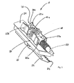
- Fig. 1 shows the connector system 1, comprising the connector 10 and the connector socket 20.
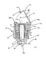
- the connector 10 consists of a connector housing 11, in which a hyperbolic radial contact 12 is formed.
- the hyperbolic radial contact 12 is constructed as a substantially cylindrical assembly of an inner sleeve 13, such as an outer sleeve 14.
- the inner sleeve 13 has a plurality of fin elements extending from the upper to the lower end of the hyperbolic radial contact.
- Such contact is commonly referred to as RADSOK contact.
- the so-called hyperbolic radial contact (RADSOK contact) furthermore has a ring element 15 which extends around the outer sleeve 14 and has a ring section 16 which extends in a form-fitting manner on the ring element 15 at a distance from the outer sleeve 14.
- the ring member 15 is formed with its ring portion 16 as a kind of circumferential ring contour with a collar which is supported in the connector housing 11.
- the connector housing 11 consists of an upper substantially cylindrical housing portion 17a and a lower housing portion 17b, which forms with the upper housing portion 17a the region of the connector 10 which carries the hyperbolic radial contact 12.
- To this housing part 17a, 17b extends perpendicular to a second substantially cylindrical housing portion 18 at approximately an angle of 90 ° away from the aforementioned housing sections 17a, 17b.
- the connector 10 has a as well as in Fig. 3 apparent geometric shape of a 90 ° angled connector, wherein the contact formed in its longitudinal extent as a hyperbolic radial contact 12 thus perpendicular to the cable outlet 50 and this surrounding the second aforementioned housing portion 18 forms.
- the connector socket 20 is formed by a substantially elongated, trapezoidal base plate 21 through which an electrically conductive contact pin 22 extends.
- the contact pin 22 has a screw receptacle 26a and a screw head 26b.
- the screw receptacle that is to say the screw thread 26a, is located at the rear plug-in end of the contact pin 22.
- Spaced apart from the base plate 21 is a contact comb 23 made of any electrically conductive material.
- the base plate 21 and the contact comb 23 are spaced apart by a spacer element 25, but arranged substantially in the form and in their surface extension parallel, so to say in pairs, spaced from each other.
- At the contact comb 23 are located at the plug-side end of a plurality of each pairwise spaced in a fixed grid pins 24th
- the contact pins 24 serve to be plugged or soldered into a corresponding printed circuit board and thus form a current carrying rail for the connector system.
- the contact comb 23 is fastened and screwed to the screw head 26b and thus to the contact pin 22 on the spacer element 25.
- the connector socket 20 further has contact-chamber ridges 29a, 29b attached to the base plate 21 to form a contact chamber 40 which is half-open.
- the contact chamber webs 29a, 29b protrude substantially vertically out of the base plate 21 and extend in height approximately to such a degree as the height of the corresponding connector 10th
- the connector 10 in its inserted state has approximately a height which corresponds approximately to the height of the contact chamber webs 29a, 29b.
- the two contact chamber webs 29a, 29b form an elongated contact chamber 40 which is open at both ends and through which the housing section 18 of the connector 10 can protrude.
- Within the contact chamber 40 are mounted on the base plate 21 in pairs at the open ends or preferably near the open ends of the contact chamber 40, respectively a Primärverrastungsklammer 30a, 30b.
- the primary tread clip 30a, 30b is in a position to be brought into a latching position with the housing portion 18 of the connector 10.
- the contour of the Primärverrastungskiammern 30 a, 30 b is adapted in its receiving area of the corresponding contour of the housing portion 18 of the connector 10.
- the connector 10 is there in the fully inserted position, wherein the housing portion 18 is clearly in operative engagement with the front Primärverrastungsklammem 30a, so it is locked.
- the secondary locking element 41 can be seen in a half-open position.
- the secondary locking element 41 is arranged pivotably mounted. That is, the secondary lock member 41 can be set from a fully opened position, which corresponds approximately to an angle of 90 °, or an extension of the extension of the contact chamber webs 29a, to a fully closed position, as in FIG Fig. 1 shown.
- the secondary locking means 21 is insofar from a hinge arm 42 at one end of a hinge pin 43 is arranged substantially as a cylindrical hinge pin. At the other end of the hinge arm 42 is a latching element 44 and an actuating element 45.
- the actuating element 45 is formed integrally with the latching element 44 and the hinge arm 42.
- the hinge arm which extends from the contact chamber land 29a to the contact chamber land 29b in the closed state, has a convex hinge arm portion. That is, the hinge arm 42 has a substantially flat Schamierarmoberseite 46 and a spaced parallel thereto Härarmarmhalteselte or bottom 47, which is convex.
- the arrangement of the hinge pin 43 and the locking elements 44 is formed so that upon actuation of the secondary locking element 41 from the open to the locked state, the convex Schamierarmhalteseite 47 is supported on the top of the connector 10, as in Fig.
- the connector 10 is held in its inserted position Federkraftbeetzschlagt. If vibrations or mechanical oscillatory loads occur, the latching between the latching element 44 and the counter-latching element 51 serves as a static bearing, while the latching, convexly curved hinge arm serves as the first Oscillating movements are resiliently intercepted and beyond the damping element, that is, preferably continue to be intercepted via at least one spring slot 49.
- the joint may be formed slotted near the hinge pin itself, whereby a resilient weak point on the secondary locking element 41 is generated.
- the hinge pin or the area above the hinge pin in the region of the contact chamber webs 29a may be formed slotted.
Landscapes
- Details Of Connecting Devices For Male And Female Coupling (AREA)
Applications Claiming Priority (1)
| Application Number | Priority Date | Filing Date | Title |
|---|---|---|---|
| DE200810019634 DE102008019634B4 (de) | 2008-04-18 | 2008-04-18 | Steckverbindersystem mit Sekundärverriegelung |
Publications (2)
| Publication Number | Publication Date |
|---|---|
| EP2110893A2 true EP2110893A2 (fr) | 2009-10-21 |
| EP2110893A3 EP2110893A3 (fr) | 2012-08-08 |
Family
ID=40635832
Family Applications (1)
| Application Number | Title | Priority Date | Filing Date |
|---|---|---|---|
| EP09004941A Withdrawn EP2110893A3 (fr) | 2008-04-18 | 2009-04-03 | Connecteur avec sortie de cäble optionnelle et verrouillage secondaire |
Country Status (2)
| Country | Link |
|---|---|
| EP (1) | EP2110893A3 (fr) |
| DE (1) | DE102008019634B4 (fr) |
Citations (2)
| Publication number | Priority date | Publication date | Assignee | Title |
|---|---|---|---|---|
| EP1369965A2 (fr) * | 2002-06-06 | 2003-12-10 | J.S.T. Mfg. Co., Ltd. | Dispositif de connection électrique |
| US20040248455A1 (en) * | 2003-06-03 | 2004-12-09 | Miller William H. | Retainer clip for ribbon cable connectors |
Family Cites Families (4)
| Publication number | Priority date | Publication date | Assignee | Title |
|---|---|---|---|---|
| JPH082939Y2 (ja) * | 1988-05-30 | 1996-01-29 | 矢崎総業株式会社 | コネクタの二重ロック装置 |
| US5482477A (en) * | 1994-06-28 | 1996-01-09 | The Whitaker Corporation | Micro-miniature coaxial connector with positive locking member |
| DE19525257C2 (de) * | 1995-07-11 | 2000-09-07 | Siemens Ag | Elektrische Steckverbindung mit Endlagen-Verriegelung |
| US5616045A (en) * | 1995-07-14 | 1997-04-01 | Augat Inc. | Squib connector for automotive air bag assembly |
-
2008
- 2008-04-18 DE DE200810019634 patent/DE102008019634B4/de not_active Expired - Fee Related
-
2009
- 2009-04-03 EP EP09004941A patent/EP2110893A3/fr not_active Withdrawn
Patent Citations (2)
| Publication number | Priority date | Publication date | Assignee | Title |
|---|---|---|---|---|
| EP1369965A2 (fr) * | 2002-06-06 | 2003-12-10 | J.S.T. Mfg. Co., Ltd. | Dispositif de connection électrique |
| US20040248455A1 (en) * | 2003-06-03 | 2004-12-09 | Miller William H. | Retainer clip for ribbon cable connectors |
Also Published As
| Publication number | Publication date |
|---|---|
| DE102008019634A1 (de) | 2009-10-22 |
| EP2110893A3 (fr) | 2012-08-08 |
| DE102008019634B4 (de) | 2010-12-02 |
Similar Documents
| Publication | Publication Date | Title |
|---|---|---|
| DE112017002366T5 (de) | Verbindersystem mit Verbinderpositionsgewährleistung | |
| EP4066325B1 (fr) | Appareil de verrouillage secondaire | |
| EP2018684B1 (fr) | Module avec des raccords pour actionneurs et/ou capteurs | |
| DE202008005394U1 (de) | Hochstromleiterplattensteckverbinder | |
| DE102020122660A1 (de) | Verbindungsvorrichtung mit einem Steckverbinder und einem Gegensteckverbinder | |
| EP4000139B1 (fr) | Élément de contact | |
| DE202017105774U1 (de) | Steckervorrichtung | |
| DE102007002766A1 (de) | Elektrischer Steckverbinder | |
| DE19952023A1 (de) | Steckverbinderkupplung | |
| DE102021133011B3 (de) | Verriegelungsvorrichtung für Steckverbindungen sowie Steckverbindung mit einer solchen Verriegelungsvorrichtung | |
| EP3671966A1 (fr) | Connecteur enfichable direct pour une carte de circuit imprimé | |
| DE102019104558A1 (de) | Steckverbinderteil mit einer Rasteinrichtung | |
| DE102012223017B4 (de) | Elektrische Steckverbindung mit einem Stecker und einer Buchse | |
| EP1705756B1 (fr) | Dispositif de verrouillage pour des connecteurs électriques | |
| DE202019106239U1 (de) | Hochfrequenz-Prüfstiftvorrichtung | |
| DE102006016909B4 (de) | Stecker mit einem Verriegelungshebel | |
| DE102012103203B4 (de) | Elektrischer Steckverbinder, insbesondere zum Aufstecken auf Leiterplatten, mit separater Kontaktträgerplatte sowie Gehäuse und Verfahren | |
| DE10248892B3 (de) | Stecker zum Verbinden mit einer Steckbuchse | |
| EP4087062B1 (fr) | Système de connexion permettant de connecter des conducteurs de signaux | |
| DE102008019634B4 (de) | Steckverbindersystem mit Sekundärverriegelung | |
| DE102005050778B4 (de) | Kontaktgehäuse sowie elektrische Kontaktvorrichtung | |
| DE102013014202B4 (de) | Steckverbindersystem | |
| DE9014856U1 (de) | Isolierkörper für elektrische Kontakte | |
| DE102004008719B4 (de) | Steckverbinder mit Verriegelungshebeln und Baugruppe mit diesem Steckverbinder | |
| EP2195887B1 (fr) | Connecteur de matrice multipolaire |
Legal Events
| Date | Code | Title | Description |
|---|---|---|---|
| PUAI | Public reference made under article 153(3) epc to a published international application that has entered the european phase |
Free format text: ORIGINAL CODE: 0009012 |
|
| AK | Designated contracting states |
Kind code of ref document: A2 Designated state(s): AT BE BG CH CY CZ DE DK EE ES FI FR GB GR HR HU IE IS IT LI LT LU LV MC MK MT NL NO PL PT RO SE SI SK TR |
|
| PUAL | Search report despatched |
Free format text: ORIGINAL CODE: 0009013 |
|
| AK | Designated contracting states |
Kind code of ref document: A3 Designated state(s): AT BE BG CH CY CZ DE DK EE ES FI FR GB GR HR HU IE IS IT LI LT LU LV MC MK MT NL NO PL PT RO SE SI SK TR |
|
| AX | Request for extension of the european patent |
Extension state: AL BA RS |
|
| RIC1 | Information provided on ipc code assigned before grant |
Ipc: H01R 13/52 20060101AFI20120629BHEP Ipc: H01R 13/639 20060101ALI20120629BHEP Ipc: H01R 13/627 20060101ALI20120629BHEP |
|
| 17P | Request for examination filed |
Effective date: 20130208 |
|
| 17Q | First examination report despatched |
Effective date: 20141223 |
|
| GRAP | Despatch of communication of intention to grant a patent |
Free format text: ORIGINAL CODE: EPIDOSNIGR1 |
|
| INTG | Intention to grant announced |
Effective date: 20171130 |
|
| STAA | Information on the status of an ep patent application or granted ep patent |
Free format text: STATUS: THE APPLICATION IS DEEMED TO BE WITHDRAWN |
|
| 18D | Application deemed to be withdrawn |
Effective date: 20180411 |