EP2111741B1 - Integrated draper belt support and skid shoe in an agricultural harvesting machine - Google Patents
Integrated draper belt support and skid shoe in an agricultural harvesting machine Download PDFInfo
- Publication number
- EP2111741B1 EP2111741B1 EP09158306A EP09158306A EP2111741B1 EP 2111741 B1 EP2111741 B1 EP 2111741B1 EP 09158306 A EP09158306 A EP 09158306A EP 09158306 A EP09158306 A EP 09158306A EP 2111741 B1 EP2111741 B1 EP 2111741B1
- Authority
- EP
- European Patent Office
- Prior art keywords
- skid
- cutting platform
- platform
- belt
- belt support
- Prior art date
- Legal status (The legal status is an assumption and is not a legal conclusion. Google has not performed a legal analysis and makes no representation as to the accuracy of the status listed.)
- Active
Links
Images



Classifications
-
- A—HUMAN NECESSITIES
- A01—AGRICULTURE; FORESTRY; ANIMAL HUSBANDRY; HUNTING; TRAPPING; FISHING
- A01D—HARVESTING; MOWING
- A01D67/00—Undercarriages or frames specially adapted for harvesters or mowers; Mechanisms for adjusting the frame; Platforms
-
- A—HUMAN NECESSITIES
- A01—AGRICULTURE; FORESTRY; ANIMAL HUSBANDRY; HUNTING; TRAPPING; FISHING
- A01D—HARVESTING; MOWING
- A01D41/00—Combines, i.e. harvesters or mowers combined with threshing devices
- A01D41/12—Details of combines
- A01D41/14—Mowing tables
-
- A—HUMAN NECESSITIES
- A01—AGRICULTURE; FORESTRY; ANIMAL HUSBANDRY; HUNTING; TRAPPING; FISHING
- A01D—HARVESTING; MOWING
- A01D57/00—Delivering mechanisms for harvesters or mowers
- A01D57/20—Delivering mechanisms for harvesters or mowers with conveyor belts
-
- A—HUMAN NECESSITIES
- A01—AGRICULTURE; FORESTRY; ANIMAL HUSBANDRY; HUNTING; TRAPPING; FISHING
- A01D—HARVESTING; MOWING
- A01D61/00—Elevators or conveyors for binders or combines
- A01D61/002—Elevators or conveyors for binders or combines transversal conveying devices
Definitions
- the present invention relates to agricultural harvesting machines, and, more particularly, to agricultural combines including a draper cutting platform.
- An agricultural harvesting machine such as a combine includes a head and a feeder housing which remove the crop material from the field, gather the crop material and transport the crop material to a separator.
- the head In the case of thinner stemmed crops such as soybeans, wheat, etc. which may be cut with a sickle bar carrying a plurality of knives, the head may also be known as a cutting platform.
- the separator removes the grain crop material from the non-grain crop material.
- the grain is cleaned and deposited in a grain tank.
- an unloading auger which is positioned alongside the combine during harvesting is moved to the unloading position in which the auger extends approximately perpendicular to the longitudinal axis of the combine.
- the combine drives alongside a vehicle into which the grain is to be unloaded, such as a semi-trailer, and the unloading auger is actuated to discharge the grain into the vehicle.
- a cutting platform may generally be of two types.
- One type typically has a sheet metal floor with a dual feed auger near the rear of the cutting platform for feeding the crop material longitudinally to the feeder housing.
- a cutting platform of this type with auger feed is more common.
- Such a platform is described in EP 1 275 287 A1 . It comprises a bottom that can be extended in the forward direction. The front part of the bottom slides on the ground, mounts a cutterbar and has a smooth upper surface.
- FIG. 1 Another type of cutting platform, also known as a draper platform, utilizes a flat, wide belt, referred to as a draper or draper belt to convey crop material.
- the arrangement and number of belts vary among platforms.
- One style of draper platform has two side belts that convey crop material longitudinally, to the center of the platform, where a center feed belt moves the crop material laterally into the feeder housing.
- Each belt is wrapped around a pair of rollers, one being a drive roller and the other being an idler roller.
- An example of this type draper arrangement is disclosed in U.S. Patent No. 6,202,397 , which is assigned to the assignee of the present invention.
- US 2007/0204589 A1 describes another draper belt platform.
- the cutterbar is mounted on float arms.
- skid plates are mounted on the underside of the float arms.
- the front end of the rollers that support the belt are mounted to the front end of the float arms which leave a space to the returning strand of the belt.
- An advantage of a draper platform is that larger amounts of crop material can be transported without plugging, etc. For example, with wide platforms approaching 12 m (40 feet) or even larger, the amount of crop material transported to the feeder housing can be substantial. With an auger feed platform, the crop material may bind between the auger and the back wall of the platform. In contrast, with a draper platform, the crop material is carried on top of the belt with less chance for plugging.
- Draper platforms currently in use have a rigid framework not allowing the framework to flex to any appreciable extent during use.
- the draper platform can be placed in a "float" position such that the cutterbar at the leading edge does not dig into the ground, but the leading edge of the platform itself cannot flex across the width of the platform as a result of uneven ground terrain. This results in some crop material being missed in ground depressions, etc., while also possibly causing a part of the cutterbar to dig into localized ground elevations (e.g., small mounds, etc.). Of course, missed crop material directly translates into missed revenue, and localized gouging of soil can cause additional repair expenses resulting from broken knives, knife guards, etc.
- Rigid platforms as described above typically include skid shoes at the bottom of the leading edge.
- the skid shoes are generally angled rearwardly and downwardly from the leading edge and are movable upwards and downwards at least slightly relative to each other.
- the skid shoes are typically stand alone components with sheet metal extending between and covering the bottom, leading edge of the skid shoes.
- belt carriers which are separate from the skid shoes carry the return run of the draper belt.
- a cutting platform for use with an agricultural harvesting machine includes at least one platform section.
- Each platform section includes a cutterbar assembly movable in a localized manner in upwards and downwards directions, an endless belt with a leading edge, and a plurality of skid shoes.
- Each skid shoe extends rearwardly from the cutterbar assembly and has an upper surface defining a belt support for the leading edge of the endless belt.
- Combine 10 includes a feeder housing 14 which is detachably coupled with cutting platform 12.
- Feeder housing 14 receives the crop material from cutting platform 12, both grain and non-grain crop material, and transports the crop material to a separator within combine 10 in known manner (not shown).
- the grain crop material is separated from the non-grain crop material, cleaned and transported to a grain tank.
- the non-grain crop material is transported to a chopper, blower, etc. in known manner and distributed back to the field.
- Cutting platform 12 generally includes a plurality of platform sections 16, 18 and 20, a cutterbar assembly 22 and a reel assembly 24.
- platform section 16 is a center platform section
- platform section 18 is a first wing platform section
- platform section 20 is a second wing platform section.
- cutting platform 12 may be configured with more or less platform sections, depending upon the particular application.
- Each platform section 16, 18 and 20 generally includes a frame 26, a plurality of float arms 28 coupled with a respective frame 26, a cutterbar 30 carried by the outboard ends of respective float arms 28, an endless belt 32, and a plurality of belt guides 34.
- the frame 26 of first wing platform section 18 and second wing platform section 20 are each pivotally coupled with center platform section 16, such that the outboard ends of first wing platform section 18 and second wing platform section 20 can move up and down independent from center platform section 16.
- a lift cylinder 36 coupled between the frame of combine 10 and feeder housing 14 lifts the entire cutting platform 12
- a first tilt cylinder 38 coupled between the respective frame 26 of first wing platform section 18 and center platform section 16 pivotally moves first wing platform section 18 relative to center platform section 16
- a second tilt cylinder 40 coupled between the respective frame 26 of second wing platform section 20 and center platform section 16 pivotally moves second wing platform section 20 relative to center platform section 16.
- Cutterbar assembly 22 includes two cutterbars 30 carried at the outboard ends of float arms 28 (i.e., at the leading edge of a platform section 16, 18 or 20).
- Each cutterbar 30 includes a plurality of knives 42 carried by a bar (not specifically shown).
- the particular type of knife can vary, such as a double blade knife (as shown) or a single blade knife.
- the bar is formed from a metal which is flexible to an extent allowing a desired degree of flexure across the width of cutting platform 12.
- a majority of each cutterbar 30 is carried by a respective first wing platform section 18 or second wing platform section 20, with a lesser extent at the adjacent inboard ends of each cutterbar 30 being carried by center platform section 16.
- Cutterbars 30 are simultaneously driven by a single knife drive 44, providing reciprocating movement in concurrent opposite directions between cutterbars 30.
- a plurality of knife guards 46 are positioned in opposition to knives 42 for providing opposing surfaces for cutting the crop material with knives 42.
- a plurality of keepers 48 spaced along cutterbars 30 have a distal end above cutterbars 30 for maintaining cutterbars 30 in place during reciprocating movement.
- Float arms 28 may be pivoted at their connection locations with a respective frame 26.
- a float cylinder 50 coupled between a respective frame 26 and float arm 28 may be used for raising or lowering the outboard end of float arm(s) 28 at the leading edge of cutting platform 12.
- Each float cylinder 50 may also be placed in a "float" position allowing the connected float arm 28 to generally follow the ground contour during operation. More particularly, each float cylinder 50 is fluidly connected with an accumulator 52 carried by a platform section 16, 18 or 20. Accumulator 52 allows fluid to flow to and from attached float cylinders 50 such that no pressure build-up occurs.
- each float cylinder 50 is free to move back and forth longitudinally, thereby allowing float arms 28 to follow the ground contour.
- float cylinders 50 can be actuated to move float arms 28 in an upward or downward direction.
- each float cylinder 50 is a hydraulic cylinder, but could possibly be configured as a gas cylinder for a particular application.
- Each float arm 28 is also associated with a respective roller 54.
- the plurality of rollers 54 for each platform section 16, 18 and 20 carry and are positioned within a loop of a respective endless belt 32.
- At the inboard end of first wing platform section 18 and second wing platform section 20 is a driven roller, and at the outboard end of first wing platform section 18 and second wing platform section 20 is an idler roller.
- the rollers positioned between the inboard drive roller and outboard idler roller at each float arm 28 also function as idler rollers. It will be appreciated that the number of float arms 28, and thus the number of rollers 54, may vary depending upon the overall width of cutting head 12 transverse to the travel direction.
- Reel assembly 24 includes two reels 56, center reel support arm 58 and a pair of outer reel support arms 60.
- Outer reel support arms 60 are pivotally coupled at one end thereof with an outboard end of a respective first wing platform section 18 or second wing platform section 20.
- Outer reel support arms 60 rotationally carry a respective reel 56 at an opposite end thereof.
- Each outer reel support arm 60 may be selectively moved up and down using a hydraulic cylinder, and the pair of hydraulic cylinders are typically coupled in parallel so that they move together upon actuation.
- Center reel support arm 58 is pivotally coupled at one end thereof with center platform section 16 above the opening leading to feeder housing 14.
- Center reel support arm 58 rotationally carries an inboard end of each reel 56 at an opposite end thereof.
- a hydraulic motor 62 or other suitable mechanical drive rotationally drives each reel 56. More particularly, hydraulic motor 62 drives a common drive shaft 64 through a chain and sprocket or other suitable arrangement (not shown). The rotational speed of reels 56 can be adjusted by an operator by adjusting the rotational speed of hydraulic motor 62.
- Center reel support arm 58 may be selectively moved up and down using a hydraulic cylinder 66. Center reel support arm 58 is movable independently from outer reel support arms 60. To accommodate this independent movement, drive shaft 64 driven by hydraulic motor 62 is coupled at each end thereof via a universal joint 68 with a respective reel 56. This independent movement of center reel support arm 58 can be accomplished manually using a separate actuating switch or lever in operator's cab 70, or automatically using an electronic controller 72 located within cab 70 or other suitable location.
- each platform section 16, 18 and 20 has a leading edge which is configured to allow cutterbar assembly 22 to flex an appreciable extent in a localized manner across the width of cutting platform 12.
- each float arm 28 has a distal end adjacent the leading edge of cutting platform 12.
- the float arms 28 associated with each respective platform section 16, 18 and 20 are mounted with a corresponding flexible substrate 74 extending substantially across the width of that particular platform section 16, 18 or 20.
- Flexible substrate 74 for each particular platform section 16, 18 and 20 in essence forms the backbone to which the other modular components (to be described hereinafter) are mounted and allows flexibility of the platform section across the width thereof.
- flexible substrate 74 is a steel plate with various mounting holes formed therein, and has a modulus of elasticity providing a desired degree of flexibility.
- the geometric configuration and material type from which flexible substrate 74 is formed may vary, depending upon the application.
- each float arm 28 is fastened to a knife guard 46, flexible substrate 74, crop ramp 76 and hold down 48.
- Cutterbar 30, including blades 44 carried by bar 78, is reciprocally carried by knife guards 46.
- Hold downs 48 which are spaced across the width of cutterbar 30 retain bar 78 within the corresponding grooves formed in knife guards 46.
- Crop ramps 76 are overlapped but not rigidly attached to each other, thereby allowing flexure during harvesting operation. Each crop ramp 76 forms an upper ledge positioned above endless belt 32 which assists in maintaining the crop material on endless belt 32 as it is transported toward feeder housing 14. In the embodiment shown in Fig. 4 , crop ramp 76 has a flat, angled orientation to assist in transport of the crop material from cutterbar assembly 22 to endless belt 32. For certain applications, it may be possible to eliminate crop ramps 76.
- Belt guides 80 are formed with both a smooth upper transition and a smooth lower transition between adjacent belt guides 80, resulting in no or little accumulation of crop material above the belt guides, and no extra wear to the endless belt 32 below the belt guides. More particularly, each belt guide 80 has a rear edge 82 with an upper surface 84 and a lower surface 86. Lower surface 86 partially overlies a leading edge 88 of endless belt 32. Upper surface 84 and lower surface 86 each have a continuous, uninterrupted contour. That is, there are no abrupt discontinuities such as recesses or projections which might tend to accumulate crop material (on top) or wear the endless belt (below). In the embodiment shown, upper surface 84 and lower surface 86 are each generally planar, but could also be formed with a slight curvature (e.g., simple or compound curvature).
- the direction of overlap between adjacent belt guides 80 is generally opposite to the travel direction of endless belt 32. However, by providing a smooth lower transition between adjacent belt guides 80, there is no undue wear to either the lip 94 or the endless belt 32. Further, the direction of overlap between adjacent belt guides 80 is in the same direction as the crop material movement across the upper surfaces thereof, resulting in little or no accumulation of crop material on top of belt guides 80.
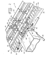
- Skid shoes 100 ( Figs. 5-8 ) are mounted at the forward end to flexible substrate 74, and thus extend rearwardly from cutterbar assembly 22.
- Skid plates 102 are detachably mounted to skid shoes 100 using fasteners 104, such as rivets, bolts or screws.
- Skid shoes 100 and skid plates 102 act in a conventional manner as a skid shoe below cutterbar assembly 22, but in addition also include an integral belt support 106 for supporting the leading edge 88 of the return run of endless belt 32.
- each skid shoe 100 includes an upper surface 108 defining belt support 106.
- Belt support 106 has a generally L-shaped cross-sectional configuration with a belt carrying surface 110 which is oriented generally parallel to the return run of the endless belt 32 when the leading edge of cutting platform 12 is in a lowered, working position.
- Skid shoes 100 are movable relative to each other and are made as a bent metal part, preferably formed as a stamped metal part from sheet metal to reduce manufacturing costs. Configured as such, each skid shoe 100 includes a hollow cavity 112 at a lower surface 114 thereof. Each skid plate 102 is mounted to the lower surface 114 of a respective skid shoe 100, and covers hollow cavity 112. During use it is possible (and in fact likely) that skid plates 102 will impinge upon various ground projections, such as rocks, sticks, hard dirt clods, etc. To inhibit deformation upon impact with such objects, each skid plate 102 includes one or more reinforcing ribs 116 which extend into hollow cavity 112 and terminate adjacent lower surface 114 of hollow cavity 112.
- each skid plate 102 includes a plurality of interconnected reinforcing ribs 116 which extend into hollow cavity 112 and terminate adjacent lower surface 114 of hollow cavity 112. Reinforcing ribs 116 allow skid plate 102 to be formed from plastic, such as with a casting process.
- Each skid shoe 100 also includes an integral and laterally extending shield 118.
- Shield 118 has a lower end 120 which is positioned below the belt carrying surface 108 of belt support 106 so as to prevent crop and other material from impinging upon or accumulating at the leading edge of endless belt 32.
- Shield 118 has a lateral end with an overlap 122 which is configured to overlap but allow movement relative to an adjacent skid shoe 100.
- Overlap 122 includes a bent lip (not numbered) which overlaps with an adjacent skid shoe 100.
- float arms 28 are placed in a float state allowing free upward and downward movement as combine 10 traverses over the ground surface.
- Cutterbar assembly 22 moves up and down with float arms 28 on a localized basis, and crop ramps 76 and belt guides 80 move relative to each other to allow the flexibility at the leading edge of each platform section 16, 18 and 20.
- Belt guides 80 also cause each belt 32 to follow the cutterbar assembly by holding down on the upper surface of the belt as cutterbar assembly 22 locally dips downward. This prevents crop material from entering beneath belt 32.
- Skid shoes 100, with attached skid plates 102 move up and down on a localized basis depending upon the ground terrain, and also concurrently carry the leading edge of the return run of endless belt 32.
- Shields 118 extending from skid shoes 100 are positioned in front of the leading edge of endless belt 32, and prevent material from impinging upon or accumulating at the leading edge of the return run of endless belt 32.
- the present invention therefore provides a cutting platform which flexes to a high degree, effciently moves crop material to the feeder housing, and maximizes harvest yield by better following the ground contour.
Landscapes
- Life Sciences & Earth Sciences (AREA)
- Environmental Sciences (AREA)
- Harvester Elements (AREA)
- Harvesting Machines For Specific Crops (AREA)
Applications Claiming Priority (1)
| Application Number | Priority Date | Filing Date | Title |
|---|---|---|---|
| US12/109,758 US20090266044A1 (en) | 2008-04-25 | 2008-04-25 | Integrated draper belt support and skid shoe in an agricultural harvesting machine |
Publications (2)
| Publication Number | Publication Date |
|---|---|
| EP2111741A1 EP2111741A1 (en) | 2009-10-28 |
| EP2111741B1 true EP2111741B1 (en) | 2011-11-23 |
Family
ID=40796280
Family Applications (1)
| Application Number | Title | Priority Date | Filing Date |
|---|---|---|---|
| EP09158306A Active EP2111741B1 (en) | 2008-04-25 | 2009-04-21 | Integrated draper belt support and skid shoe in an agricultural harvesting machine |
Country Status (7)
| Country | Link |
|---|---|
| US (5) | US20090266044A1 (pt) |
| EP (1) | EP2111741B1 (pt) |
| AR (1) | AR071407A1 (pt) |
| AT (1) | ATE534283T1 (pt) |
| BR (1) | BRPI0900950A2 (pt) |
| RU (1) | RU2493686C2 (pt) |
| UA (1) | UA104124C2 (pt) |
Families Citing this family (42)
| Publication number | Priority date | Publication date | Assignee | Title |
|---|---|---|---|---|
| US20070193243A1 (en) * | 2006-02-10 | 2007-08-23 | Schmidt James R | Combine Harvester Draper Header Having Flexible Cutterbar |
| US20080276590A1 (en) * | 2006-02-10 | 2008-11-13 | Agco Corporation | Flexible draper and cutter bar with tilt arm for cutterbar drive |
| US20080271426A1 (en) * | 2006-02-10 | 2008-11-06 | Agco Corporation | Draper belt with crop-retaining rib |
| US20090266044A1 (en) * | 2008-04-25 | 2009-10-29 | Coers Bruce A | Integrated draper belt support and skid shoe in an agricultural harvesting machine |
| US7886511B2 (en) * | 2008-05-09 | 2011-02-15 | Agco Corporation | Draper head with flexible cutterbar having rigid center section |
| EP2315514B1 (en) | 2008-05-09 | 2012-04-25 | Agco Corporation | Adjustable cutterbar travel range for a flexible cutterbar header |
| US20090277144A1 (en) * | 2008-05-09 | 2009-11-12 | Agco Corporation | Spring flotation for center deck of draper header |
| US20090277148A1 (en) | 2008-05-09 | 2009-11-12 | Agco Corporation | Flexible draper and cutter bar having shiftable crop divider with deflector |
| US7640720B1 (en) * | 2008-06-11 | 2010-01-05 | Deere & Company | Draper belt construction to control translation |
| US7975462B1 (en) * | 2010-05-13 | 2011-07-12 | Cnh America Llc | Modular floor assembly for a combine header |
| US8205421B2 (en) * | 2010-06-16 | 2012-06-26 | Agco Corporation | Belt guard crop dam for flexible draper header |
| US8402728B2 (en) * | 2010-06-25 | 2013-03-26 | Macdon Industries Ltd. | Guide arrangement for the draper of a combine harvester pick-up |
| US8322520B2 (en) * | 2010-08-17 | 2012-12-04 | Deere & Company | Tongue-in-groove belt hold down for a draper platform |
| US8479483B1 (en) * | 2011-12-27 | 2013-07-09 | Agco Corporation | Flexible draper head providing reduced crop residue accumulation |
| EP2797403B1 (en) * | 2011-12-28 | 2016-11-30 | Agco Corporation | Skid plate for crop header having flexible cutterbar |
| DE102012011912A1 (de) | 2012-06-15 | 2013-12-19 | Biso Schrattenecker Gmbh | Erntevorsatz für eine Erntemaschine |
| US8511050B1 (en) * | 2012-08-31 | 2013-08-20 | Macdon Industries Ltd. | Draper support of a crop harvesting header |
| US8752359B2 (en) * | 2012-08-31 | 2014-06-17 | Macdon Industries Ltd. | Draper support of a crop harvesting header |
| US8484939B1 (en) * | 2012-08-31 | 2013-07-16 | Macdon Industries Ltd. | Draper seal for crop harvesting header |
| DE102012108708B4 (de) * | 2012-09-17 | 2015-02-05 | Thomas Reiter | Erntegutaufnehmer |
| CA2799093A1 (en) * | 2012-12-18 | 2014-06-18 | Honey Bee Manufacturing Ltd. | Draper seal for crop header |
| US9198349B2 (en) * | 2013-07-12 | 2015-12-01 | Deere & Company | Articulated harvesting head ground force control circuit |
| US9861036B2 (en) | 2014-07-15 | 2018-01-09 | Cnh Industrial America Llc | Skid shoe for a header of an agricultural harvester |
| US9591802B2 (en) * | 2015-04-28 | 2017-03-14 | Jose Luis Allochis | Belt sealing crop deflector for a flexible draper platform |
| US10575462B2 (en) * | 2016-10-14 | 2020-03-03 | Deere & Company | Sickle bar drive mount |
| WO2018091958A1 (en) * | 2016-11-17 | 2018-05-24 | Agco Corporation | Header float and skin plate adjustment |
| US10477768B2 (en) * | 2017-05-23 | 2019-11-19 | Cnh Industrial America Llc | Extendable draper belt |
| US11589512B2 (en) * | 2017-07-25 | 2023-02-28 | Cnh Industrial America Llc | Draper support for a draper belt assembly of an agricultural harvester |
| JP2019103404A (ja) * | 2017-12-08 | 2019-06-27 | 株式会社クボタ | コンバイン |
| JP2019103406A (ja) * | 2017-12-08 | 2019-06-27 | 株式会社クボタ | コンバイン |
| US10568263B2 (en) | 2017-12-14 | 2020-02-25 | Cnh Industrial America Llc | Linkage assembly for header height control |
| US10813290B2 (en) * | 2018-06-11 | 2020-10-27 | Deere & Company | Component and method for crop ramp and belt support |
| US10918017B2 (en) * | 2018-07-10 | 2021-02-16 | Macdon Industries Ltd | Draper canvas seal |
| US10999965B2 (en) | 2018-08-06 | 2021-05-11 | Clark Adam Garner | Hydraulically actuated litter level |
| US10945374B2 (en) * | 2018-10-15 | 2021-03-16 | Deere & Company | Combine head skid plate with optimized shape |
| WO2020101993A1 (en) * | 2018-11-16 | 2020-05-22 | Cnh Industrial America Llc | Harvester header with lateral belt roller mount |
| CA3130151A1 (en) * | 2019-03-21 | 2020-09-24 | Bradley J. Wenger | Floating floor assembly of a header |
| US11324166B2 (en) * | 2019-10-16 | 2022-05-10 | Deere & Company | Harvester row head |
| US11617305B2 (en) | 2020-05-21 | 2023-04-04 | Cnh Industrial America Llc | Crop ramps for combine headers |
| DE102021107187A1 (de) * | 2021-03-23 | 2022-09-29 | Claas Selbstfahrende Erntemaschinen Gmbh | Bandschneidwerk |
| US12550823B2 (en) * | 2022-06-15 | 2026-02-17 | Cnh Industrial America Llc | Agricultural header with a draper belt including a seed saver disposed behind one or more crop ramps |
| USD1058615S1 (en) * | 2023-07-18 | 2025-01-21 | Macdon Industries Ltd. | Skid shoe |
Family Cites Families (245)
| Publication number | Priority date | Publication date | Assignee | Title |
|---|---|---|---|---|
| US515549A (en) | 1894-02-27 | Half to benjamin j | ||
| US98220A (en) * | 1869-12-28 | of canton | ||
| US391383A (en) | 1888-10-16 | myeick | ||
| CA887374A (en) | 1971-12-07 | Massey-Ferguson G.M.B.H. | Telescopic table with detachable knife sections | |
| US663318A (en) * | 1900-04-30 | 1900-12-04 | James Porteous | Finger-guard bar for headers or harvesters. |
| US923084A (en) | 1908-10-05 | 1909-05-25 | David H Simmons | Apparatus for straightening grain upon harvesters. |
| US1678549A (en) * | 1925-04-10 | 1928-07-24 | Peter H Bergen | Pick-up grain guard |
| US1580646A (en) | 1925-05-01 | 1926-04-13 | John C Brattly | Guard for grain-binder conveyers |
| US1914837A (en) | 1927-01-26 | 1933-06-20 | Caterpillar Tbactor Co | Windrow header |
| US1990054A (en) | 1927-11-02 | 1935-02-05 | Caterpillar Tractor Co | Header pick-up |
| GB314315A (en) | 1928-03-19 | 1929-06-19 | Western Harvester Company | Improvements in or relating to harvesters |
| US1928236A (en) | 1931-03-23 | 1933-09-26 | Caterpillar Tractor Co | Harvester |
| US1917604A (en) * | 1931-04-30 | 1933-07-11 | Avery Power Machinery Co | Sickle guard and shield |
| US1862101A (en) | 1931-05-02 | 1932-06-07 | Jacob G Pax | Harvester |
| US1881411A (en) | 1931-07-13 | 1932-10-04 | James E Love | Pea harvester |
| US1996294A (en) * | 1934-02-27 | 1935-04-02 | Horace D Hume | Harvester |
| US2054161A (en) * | 1935-04-08 | 1936-09-15 | John L Leonard | Soy bean or like harvesting adapter for binders |
| US2102710A (en) * | 1935-11-18 | 1937-12-21 | Hume Love Company | Harvester |
| US2099471A (en) | 1937-03-05 | 1937-11-16 | Cheney Weeder Company | Harvester attachment |
| US2240066A (en) | 1939-10-10 | 1941-04-29 | John W Bingham | Bean harvester and windrower |
| US2237517A (en) | 1940-01-02 | 1941-04-08 | Deere & Co | Harvester platform |
| US2347365A (en) | 1941-10-18 | 1944-04-25 | Deere & Co | Harvesting mechanism |
| US2389193A (en) | 1944-08-18 | 1945-11-20 | Earl C Graves | Supplemental feed for drapers |
| US2438065A (en) | 1944-10-02 | 1948-03-16 | James E Love | Harvesting mechanism |
| US2599438A (en) | 1948-10-28 | 1952-06-03 | Int Harvester Co | Floating cutter bar for harvesters |
| US2795922A (en) | 1953-07-27 | 1957-06-18 | Horace D Hume | Floating cutter bar for harvesters |
| GB746108A (en) | 1954-01-28 | 1956-03-07 | Julius Ommodt | Improvements in or relating to reaping machines |
| GB773685A (en) | 1954-02-05 | 1957-05-01 | Harold Cecil John Jackson | Combine harvester |
| GB777590A (en) | 1954-09-27 | 1957-06-26 | Gordon Eric Debenham | An improved agricultural crop-cutting machine |
| GB825842A (en) | 1955-01-27 | 1959-12-23 | Massey Ferguson Inc | Improved swather |
| US2912814A (en) | 1957-06-18 | 1959-11-17 | Ford Motor Co | Cutter bar drive |
| US2915870A (en) * | 1958-03-27 | 1959-12-08 | Horace D Hume | Floating cutter bar support mounting |
| US2999348A (en) | 1959-04-20 | 1961-09-12 | Cunningham & Sons | Windrower mechanism |
| US3021660A (en) * | 1959-05-29 | 1962-02-20 | Huseman Martin | Gauge attachment for combines |
| US3092116A (en) | 1961-08-14 | 1963-06-04 | Clark E Stroburg | Grain deflector and leveler for combines |
| US3168800A (en) * | 1962-11-09 | 1965-02-09 | Owatonna Mfg Company Inc | Adjustable skid shoe for swathers and the like |
| BE658489A (pt) | 1964-02-12 | 1965-05-17 | ||
| US3216184A (en) * | 1964-03-05 | 1965-11-09 | Harold W Grimm | Sickle bar outer shoe |
| US3283485A (en) | 1964-05-25 | 1966-11-08 | Sperry Rand Corp | Drive system for agricultural machine |
| US3324639A (en) * | 1964-07-23 | 1967-06-13 | Sperry Rand Corp | Auger header and crop conditioner |
| US3304699A (en) | 1964-08-11 | 1967-02-21 | Sperry Rand Corp | Harvester header construction |
| US3597907A (en) * | 1965-02-15 | 1971-08-10 | Love Co J E | Header elevational control system for crop-harvesting machine |
| US3412735A (en) | 1965-10-20 | 1968-11-26 | Deere & Co | Dividers for a combine separator |
| US3656286A (en) * | 1970-10-30 | 1972-04-18 | Joseph Glunk | Mowing machine |
| CH579194A5 (pt) | 1971-06-14 | 1976-08-31 | Mannesmann Leichtbau Gmbh | |
| US3763637A (en) | 1972-01-17 | 1973-10-09 | H Schmitt | Reversible chassis for self-propelling combines |
| US3851451A (en) | 1972-03-23 | 1974-12-03 | Deere & Co | Automatic height control system for a crop harvester |
| US3808783A (en) * | 1972-06-07 | 1974-05-07 | Deere & Co | Soybean harvesting header |
| SU445392A1 (ru) | 1972-06-30 | 1974-10-05 | Жатка | |
| US3783594A (en) | 1972-09-18 | 1974-01-08 | Int Harvester Co | Harvester platform suspension and linkage system |
| US3813859A (en) | 1972-10-13 | 1974-06-04 | Love J Co | Cutterbar improvements in a harvesting machine |
| GB1459684A (en) | 1973-06-14 | 1976-12-22 | Clayson Nv | Agricultural machines |
| US3866400A (en) | 1974-01-21 | 1975-02-18 | Love Co J E | Feeder panel for a harvesting machine |
| US3885377A (en) | 1974-03-08 | 1975-05-27 | Nor Lo Engineering Co | Crop divider for harvester |
| US3886718A (en) | 1974-05-17 | 1975-06-03 | John M Talbot | Automatic header height control system for combines and the like |
| US3941003A (en) | 1974-07-09 | 1976-03-02 | Hesston Corporation | Balanced sickle drive |
| US4011709A (en) * | 1974-11-13 | 1977-03-15 | Deere & Company | Harvesting platform |
| US3982383A (en) * | 1974-11-13 | 1976-09-28 | Deere & Company | Harvesting platform with a floating cutter bar |
| US3958399A (en) * | 1975-02-18 | 1976-05-25 | Sperry Rand Corporation | Header attachment structure |
| US3982384A (en) * | 1975-02-21 | 1976-09-28 | Deere & Company | Row crop harvesting header |
| US3967437A (en) | 1975-06-13 | 1976-07-06 | Deere & Company | Indicator for a harvesting platform |
| US3967439A (en) | 1975-07-24 | 1976-07-06 | Deere & Company | Crop divider for a harvester |
| DE2638685C2 (de) | 1975-09-18 | 1982-06-24 | Avco Corp., 06830 Greenwich, Conn. | Vorrichtung zum freitragenden Befestigen einer Schneidstangenanordnung |
| US4008556A (en) | 1976-02-19 | 1977-02-22 | Deere & Company | Isolated harvester cutter bar |
| CA1056162A (en) | 1976-08-13 | 1979-06-12 | Graeme R. Quick | Cutterbar for a crop harvesting machine |
| US4195467A (en) | 1976-12-20 | 1980-04-01 | Robert George Frean | Harvesting machines |
| CA1079984A (en) | 1977-02-07 | 1980-06-24 | Graeme R. Quick | Crop harvesting machine |
| US4124970A (en) | 1977-06-03 | 1978-11-14 | Sperry Rand Corporation | Automatic reel height control for a harvester header having a flexible cutterbar |
| US4211057A (en) | 1978-03-20 | 1980-07-08 | Massey-Ferguson Industries Limited | Combine harvester automatic table height control |
| US4191006A (en) | 1978-05-08 | 1980-03-04 | International Harvester Company | Floating cutterbar knife drive |
| US4171606A (en) | 1978-06-30 | 1979-10-23 | Deere & Company | Attitude control for a harvester pickup |
| US4206583A (en) | 1978-09-01 | 1980-06-10 | International Harvester Company | Cutterbar floatation system |
| US4206584A (en) | 1978-09-01 | 1980-06-10 | International Harvester Company | Floating cutterbar header |
| US4227363A (en) | 1978-09-01 | 1980-10-14 | International Harvester Company | Floating cutterbar header and height control |
| US4246742A (en) | 1978-12-11 | 1981-01-27 | Hesston Corporation | Double sickle mechanism |
| US4206582A (en) | 1979-02-12 | 1980-06-10 | International Harvester Company | Header lift arrangement for windrowers |
| US4216641A (en) | 1979-06-13 | 1980-08-12 | Sperry Corporation | Crop harvesting machine |
| US4266391A (en) | 1979-11-05 | 1981-05-12 | Sperry Corporation | Header attachment mechanism for combines |
| US4266392A (en) | 1979-11-05 | 1981-05-12 | Sperry Corporation | Header cutting angle adjustment mechanism |
| US4253295A (en) | 1979-11-05 | 1981-03-03 | Sperry Corporation | Lateral float mechanism for combines |
| NZ195877A (en) | 1980-01-10 | 1984-07-31 | Massey Ferguson Services Nv | Crop collecting table or platform for combine harvester and height control thereof |
| US4332126A (en) | 1980-09-11 | 1982-06-01 | Deere & Company | Automatic height control for a harvester header |
| US4330984A (en) | 1980-10-03 | 1982-05-25 | Hillmann De Lloyd F | Crop divider assembly |
| US4296592A (en) | 1980-11-03 | 1981-10-27 | Sperry Corporation | Auger floatation limit |
| US4372103A (en) | 1980-11-24 | 1983-02-08 | Sperry Corporation | Combine drive belt shielding |
| US4307560A (en) | 1980-11-28 | 1981-12-29 | International Harvester Company | Header height position control for a cotton harvester |
| US4330983A (en) | 1980-12-01 | 1982-05-25 | J. E. Love Company | Floating divider for a harvester |
| GB2105963A (en) | 1981-09-24 | 1983-04-07 | Nat Res Dev | Unmanned two row root crop harvester |
| US4414793A (en) | 1981-09-28 | 1983-11-15 | Sperry Corporation | Flexible crop harvesting header |
| US4407110A (en) | 1981-09-28 | 1983-10-04 | Sperry Corporation | Frame for crop harvesting header |
| US4429517A (en) | 1981-10-06 | 1984-02-07 | Hesston Corporation | Harvesting header with adjustable draper for left, right or center delivery |
| US4409780A (en) | 1982-03-11 | 1983-10-18 | Kansas State University Research Foundation | Folding header assembly |
| DE3213542A1 (de) | 1982-04-10 | 1983-10-20 | Klemens 4730 Ahlen Kalverkamp | Verfahren und geraet zum ernten von mais oder anderen koernerfruechten |
| CA1204599A (en) | 1982-08-30 | 1986-05-20 | Michael H. Enzmann | Harvester header with floating cutter bar |
| US4446683A (en) | 1982-09-29 | 1984-05-08 | Canadian Cooperative Implements Limited | Knife drive |
| US4473993A (en) | 1983-05-26 | 1984-10-02 | Sperry Corporation | Cutting angle adjustment mechanism for crop harvesting machines |
| US4541229A (en) | 1983-06-27 | 1985-09-17 | Elijah Jerry D | Control system for combine header |
| US4538404A (en) | 1983-08-16 | 1985-09-03 | General Dryer Corporation | Adjustable crop divider apparatus |
| US4441307A (en) * | 1983-08-30 | 1984-04-10 | Allis-Chalmers Corporation | Harvester header with floating cutter bar |
| US4674626A (en) | 1983-12-15 | 1987-06-23 | M. L. Eakes Co. | Leakproof endless belt conveyor |
| NL8402348A (nl) | 1983-12-22 | 1985-07-16 | Multinorm Bv | Voertuig, in het bijzonder landbouwmachine, met tenminste twee verend aan het gestel opgehangen loopwielen. |
| GB8403017D0 (en) | 1984-02-04 | 1984-03-07 | Sperry Nv | Crop gathering attachment |
| US4573308A (en) | 1984-04-02 | 1986-03-04 | Deere & Company | Harvesting platform with a floating cutterbar |
| US4493181A (en) | 1984-05-14 | 1985-01-15 | Farmer's Factory Co. | Attachment for the snouts of combines and the like |
| DE3441209A1 (de) | 1984-11-10 | 1986-05-15 | Claas Ohg, 4834 Harsewinkel | Schneidwerksmulde fuer erntemaschinen mit flexiblem schneidwerk |
| US4722172A (en) | 1985-02-04 | 1988-02-02 | Pearce Charles E | Harvesters |
| DE3512619A1 (de) | 1985-04-06 | 1986-10-09 | Claas Ohg, 4834 Harsewinkel | Schneidwerksmulde fuer einen selbstfahrenden maehdrescher |
| US4845931A (en) * | 1985-07-22 | 1989-07-11 | Rippelton, N.V. | Apparatus for a harvesting machine |
| US4599852A (en) * | 1985-07-24 | 1986-07-15 | J. I. Case Company | Adjustable leaf spring suspension for flexible cutterbar |
| EP0215142B1 (de) | 1985-09-14 | 1990-06-06 | Deere & Company | Halmteiler für landwirtschaftliche Maschinen |
| US4660360A (en) * | 1985-10-15 | 1987-04-28 | J. I. Case Company | Flexible cutterbar assembly |
| US4776153A (en) | 1986-02-27 | 1988-10-11 | Deere & Company | Automatic height control for a laterally pivoted harvester header |
| DE3673519D1 (de) | 1986-05-02 | 1990-09-20 | Ford New Holland Inc | Maehtisch-querschwingungsvorrichtung fuer landwirtschaftliche maschine. |
| DE3674404D1 (de) * | 1986-06-24 | 1990-10-25 | Ford New Holland Inc | Schneidtisch fuer erntemaschine. |
| US4757673A (en) | 1986-07-29 | 1988-07-19 | Charles Gayman | Adjustment of crop dividers |
| US4724661A (en) | 1986-09-04 | 1988-02-16 | New Holland Inc. | Two piece crop harvesting header and flotation mechanism therefor |
| US4729212A (en) * | 1986-09-18 | 1988-03-08 | Rabitsch Thermon D | Protective cover for combine skid plates |
| DE3722143C2 (de) * | 1987-07-04 | 1996-03-28 | Claas Ohg | Gutaufnahmevorrichtung für Erntemaschinen, insbesondere für selbstfahrende Mähdrescher |
| US4815265A (en) | 1987-07-14 | 1989-03-28 | Hay & Forage Industries | Harvesting header having timed double sickle toothed belt drive |
| US4813296A (en) | 1987-08-10 | 1989-03-21 | Hesston Corporation | Flywheel sickle drive mechanism |
| DD271010A3 (de) | 1987-08-14 | 1989-08-23 | Fortschritt Veb K | Messerantrieb fuer feldfutterschneidwerke |
| GB2208581B (en) | 1987-08-14 | 1991-07-10 | Agricultural Plant Hire Limite | Crop lifters |
| DE3733619A1 (de) | 1987-10-05 | 1989-04-13 | Deere & Co | Verfahren zum gleichmaessigen verteilen eines zu trennenden guts in einer trenneinrichtung und mittel zu seiner ausfuehrung |
| IT1213910B (it) | 1987-10-09 | 1990-01-05 | F I R I E Di Giorgio Sansone S | Nastro trasportatore e o accompagnatore a bordi nervati per la guida su cilindri di rinvio e trascinamento |
| EP0312655B1 (en) | 1987-10-22 | 1993-12-22 | New Holland Belgium N.V. | Combine harvester cleaning apparatus |
| US4835954A (en) | 1988-02-03 | 1989-06-06 | Deutz-Allis Corporation | Combine header with skid plates |
| DE3807610A1 (de) | 1988-03-09 | 1989-09-21 | Claas Ohg | Vorrichtung und verfahren zur lageregelung eines maehwerkes |
| US4938010A (en) * | 1988-05-20 | 1990-07-03 | Hay & Forage Industries | Harvesting header having adjustable width, draper belt discharge opening |
| US4896486A (en) | 1988-06-07 | 1990-01-30 | Lundahl Research, Inc. | Crop harvester having height control |
| RU1828389C (ru) | 1988-06-22 | 1993-07-15 | Макдон Индастриз Лтд | Жатка зерноуборочного комбайна |
| US5005343A (en) * | 1988-06-22 | 1991-04-09 | Macdon Industries Ltd. | Header for a combine harvesting machine |
| US4956966A (en) * | 1988-06-22 | 1990-09-18 | Macdon Industries Ltd. | Header for a combine harvesting machine |
| US4891932A (en) | 1989-06-19 | 1990-01-09 | Johnson William A | Grain-saver dam for combine cutter bar |
| US5005342A (en) | 1990-02-13 | 1991-04-09 | Ezra C. Lundahl, Inc. | Crop processor |
| US5105610A (en) | 1991-04-25 | 1992-04-21 | Britten Ethan F | Crop stalk guide cutterbar attachment |
| US5157905A (en) | 1991-04-29 | 1992-10-27 | Macdon Industries Ltd. | Support linkage for mounting a header on a support frame |
| US5243810A (en) | 1991-10-28 | 1993-09-14 | Macdon Industries | Header transport system |
| US5174101A (en) * | 1991-11-14 | 1992-12-29 | Rabitsch Thermon D | Protective cover for combine skid plates |
| US5282771A (en) | 1992-05-29 | 1994-02-01 | Probe Adventures, Inc. | Combine sieve levelling apparatus |
| US5338257A (en) | 1992-05-29 | 1994-08-16 | Probe Adventures, Inc. | Combine sieve distributor apparatus |
| CA2110775C (en) | 1993-12-06 | 1999-03-02 | Gregory J. Honey | A feeder adapter for mounting a combine header to a feeder housing of a combine |
| CA2138939C (en) | 1994-12-22 | 2003-04-15 | Francois Talbot | Draper header with canvas to cutter bar seal |
| US5459986A (en) * | 1994-12-27 | 1995-10-24 | Macdon Industries Ltd. | Draper header with canvas to cutter bar seal |
| DE19504244C2 (de) | 1995-02-09 | 1996-12-12 | Claas Ohg | Selbstfahrender Mähdrescher mit zweigeteiltem Schneidtisch |
| DE19523255A1 (de) | 1995-06-27 | 1997-01-02 | Claas Saulgau Gmbh | Erntevorsatz an landwirtschaftlichen Arbeitsmaschinen zum Aufnehmen und Weiterführen von Halmfrüchten, beispielsweise Maispflanzen |
| US5661964A (en) | 1995-10-11 | 1997-09-02 | Pixall Limited Partnership | Fresh market sweet corn harvester |
| US5924270A (en) * | 1995-11-16 | 1999-07-20 | May-Wes Manufacturing, Inc. | Skid shoe |
| CA2180627C (en) | 1996-07-05 | 2003-10-21 | Douglas Keith Rogalsky | Reversible hydraulic drive apparatus |
| US5865019A (en) | 1996-12-17 | 1999-02-02 | New Holland North America, Inc. | Plastic divider assembly with frame for a corn head |
| US6029429A (en) * | 1997-02-27 | 2000-02-29 | Macdon Industries Ltd. | Header for a crop harvesting machine with adjustment of a longitudinal shape of the cutter bar |
| USD423522S (en) * | 1998-05-28 | 2000-04-25 | Global Polymer Industries, Inc. | Combine head skid shoe |
| US6070401A (en) | 1998-08-28 | 2000-06-06 | Johnson; William A. | Grain saver dam |
| US6305154B1 (en) | 1999-03-30 | 2001-10-23 | Alamo Group Inc. | High speed sickle cutting system |
| US6510681B2 (en) | 1999-03-30 | 2003-01-28 | Alamo Group Inc. | High speed sickle cutting system |
| US6202397B1 (en) * | 1999-05-27 | 2001-03-20 | Deere & Company | Draper belt tensioning mechanism for a harvesting platform |
| AU2003204399B8 (en) | 1999-05-28 | 2005-11-17 | Deere & Company | Header for a harvester having an integral transport system |
| US6116010A (en) | 1999-05-28 | 2000-09-12 | Deere & Company | Knife guard for a cutterbar assembly |
| US6247297B1 (en) | 1999-08-20 | 2001-06-19 | Case Corporation | Jackknife support system for a combine cornhead |
| US6396721B1 (en) | 2000-02-03 | 2002-05-28 | Kabushiki Kaisha Toshiba | Power converter control device and power converter thereof |
| USD446222S1 (en) * | 2000-04-03 | 2001-08-07 | Mark W. Bruns | Skid shoe |
| CA2307176A1 (en) | 2000-04-27 | 2001-10-27 | Thomas Russell Fox | Header with flexible crop cutting knife |
| US6530197B1 (en) | 2000-05-16 | 2003-03-11 | Deere & Company | Ground contact height sensor |
| US6351931B1 (en) * | 2000-06-09 | 2002-03-05 | Macdon Industries Ltd. | Crop header with draper canvas |
| EP1298979B1 (en) | 2000-07-04 | 2008-03-12 | Robert John Eyre | Harvesting machine |
| AU2006207881A1 (en) | 2000-09-01 | 2006-10-05 | Schutt, Craig James | Combine harvesters |
| FR2813492B1 (fr) | 2000-09-06 | 2006-09-01 | Hydrotronic | Barre de coupe pour moissonneuse-batteuse ou engin similaire |
| USD454576S1 (en) * | 2000-10-23 | 2002-03-19 | Global Polymer Industries, Inc. | Combine head skid shoe |
| DE10108516A1 (de) | 2001-02-22 | 2002-08-29 | Kemper Gmbh Maschf | Maschine zum Mähen von stängelartigem Erntegut |
| US20020129591A1 (en) | 2001-03-19 | 2002-09-19 | Patterson Roger L. | Crop stripper for the crop transport draper of a header |
| US6588187B2 (en) | 2001-06-05 | 2003-07-08 | Deere & Company | Harvester row unit height control with electrohydraulic proportional valve structure |
| CA2387898C (en) * | 2001-06-18 | 2005-01-11 | Macdon Industries Ltd. | Multi-section header with flexible crop cutting knife |
| US6615570B2 (en) | 2001-06-28 | 2003-09-09 | Deere & Company | Header position control with forward contour prediction |
| DE10133105A1 (de) * | 2001-07-12 | 2003-02-06 | Claas Selbstfahr Erntemasch | Schneidwerk für Erntemaschinen |
| US6666007B2 (en) | 2001-12-12 | 2003-12-23 | Case Corporation | Hydro-mechanical variable speed feeder/header drive for an agricultural combine |
| CA2369862C (en) | 2002-01-31 | 2009-10-27 | Norbert Beaujot | Header height control apparatus |
| DE10221983A1 (de) | 2002-05-17 | 2003-11-27 | Kemper Gmbh Maschf | Erntevorsatz |
| DE10227484A1 (de) | 2002-06-19 | 2004-02-26 | Claas Selbstfahrende Erntemaschinen Gmbh | Vorrichtung und Verfahren zur Lagesteuerung eines Erntegutaufnahmegerätes landwirtschaftlicher Erntemaschinen |
| US6705067B2 (en) | 2002-07-16 | 2004-03-16 | Case Corporation | Feed conveyor/rock trap and header drive for an agricultural combine |
| US6663525B1 (en) | 2002-07-17 | 2003-12-16 | Case Corporation | Hydro-mechanical transmission with automatic braking capability and method of operation |
| GB2392600A (en) | 2002-09-04 | 2004-03-10 | Cnh Belgium Nv | Cutting platform for a combine harvester |
| US20040065069A1 (en) | 2002-10-02 | 2004-04-08 | Dunn James Thomas | Crop harvesting machine with recoil action on impact with an obstacle |
| DE10302694A1 (de) | 2003-01-24 | 2004-07-29 | Maschinenfabrik Kemper Gmbh & Co. Kg | Antriebssystem für einen Erntevorsatz einer Erntemaschine |
| DE10302692B4 (de) | 2003-01-24 | 2019-03-07 | Maschinenfabrik Kemper Gmbh & Co. Kg | Antriebssystem für einen Erntevorsatz einer Erntemaschine |
| CA2461790C (en) * | 2003-05-01 | 2011-05-10 | Macdon Industries Ltd. | Sickle knife with double overlapping out of phase sickles |
| CA2434981C (en) | 2003-07-11 | 2006-05-02 | Macdon Industries Ltd. | Crop feed draper for a header |
| US6865871B2 (en) | 2003-07-14 | 2005-03-15 | Macdon Industries Ltd. | Crop feed arrangement for the header of a combine harvester |
| US6883299B1 (en) | 2003-08-05 | 2005-04-26 | Richard Gramm | Height sensor arrangement for agricultural applications |
| US6843719B1 (en) | 2003-10-30 | 2005-01-18 | David Sacquitne | Floating combine sieve assembly |
| US6983583B2 (en) | 2003-11-21 | 2006-01-10 | Ariens Company | Lawnmower tilt sensor apparatus and method |
| US6889492B1 (en) | 2003-11-25 | 2005-05-10 | Cnh America Llc | Reversing transfer drive for sickle cutting knives on a header of an agricultural combine |
| DE102004042437A1 (de) | 2004-08-31 | 2006-03-16 | Claas Selbstfahrende Erntemaschinen Gmbh | Vorsatzgerät für Erntemaschinen |
| CA2494034C (en) | 2005-01-25 | 2009-12-08 | Macdon Industries Ltd. | Wear shield for the cutter bar of a crop cutting machine |
| KR100632953B1 (ko) * | 2005-03-07 | 2006-10-12 | 삼성전자주식회사 | 메모리 소자, 상기 메모리 소자를 위한 메모리 배열 및 상기 메모리 배열의 구동 방법 |
| US7222474B2 (en) | 2005-04-29 | 2007-05-29 | Cnh America Llc | Ground sensing apparatus for a header of an agricultural harvesting machine |
| US7430846B2 (en) | 2005-05-10 | 2008-10-07 | Deere & Company | Floating header with integrated float system for use with an agricultural windrower or combine |
| US7222475B2 (en) | 2005-05-10 | 2007-05-29 | Deere & Company | Header hydraulic float system |
| US7207164B2 (en) * | 2005-05-10 | 2007-04-24 | Deere & Company | Header hydraulic float suspension |
| US7191582B2 (en) | 2005-05-10 | 2007-03-20 | Deere & Company | Header terrain following system |
| EP1726202B1 (en) | 2005-05-25 | 2008-01-23 | CNH Belgium N.V. | Guard for a header of a harvester. |
| US7121074B1 (en) | 2005-05-31 | 2006-10-17 | Acco Corporation | Balanced epicyclic sickle drive |
| AU2006255149A1 (en) | 2005-06-08 | 2006-12-14 | Legg Company Inc. | Draper belt having improved durability |
| DE202005016401U1 (de) | 2005-10-19 | 2007-02-22 | Alois Pöttinger Maschinenfabrik Gmbh | Erntemaschine |
| US7306513B2 (en) | 2005-11-30 | 2007-12-11 | Deere & Company | Leveling by over-compensation |
| US7197865B1 (en) | 2005-12-22 | 2007-04-03 | Macdon Industries Ltd. | Self contained transport for crop harvesting header |
| US20070193243A1 (en) | 2006-02-10 | 2007-08-23 | Schmidt James R | Combine Harvester Draper Header Having Flexible Cutterbar |
| US20080276590A1 (en) | 2006-02-10 | 2008-11-13 | Agco Corporation | Flexible draper and cutter bar with tilt arm for cutterbar drive |
| US20080271426A1 (en) | 2006-02-10 | 2008-11-06 | Agco Corporation | Draper belt with crop-retaining rib |
| BRPI0700408B1 (pt) | 2006-02-17 | 2016-04-19 | Deere & Co | conjunto de ponta e tampa para um cabeçote de colheita de fileira |
| KR101178122B1 (ko) * | 2006-02-22 | 2012-08-29 | 삼성전자주식회사 | 플래시 메모리 장치, 플래시 메모리 장치를 소거하는 방법,그리고 그 장치를 포함한 메모리 시스템 |
| US20070204586A1 (en) | 2006-03-02 | 2007-09-06 | Deere & Company, A Delaware Corporation | Knife drive for multiple cutterbars in an agricultural machine |
| US7600364B2 (en) | 2006-03-02 | 2009-10-13 | Deere & Company | Sectionalized belt guide for draper belt in an agricultural harvesting machine |
| US7478521B2 (en) * | 2006-03-02 | 2009-01-20 | Deere & Company | Flexible cutting platform to follow ground contour in an agricultural harvesting machine |
| US7412816B2 (en) * | 2006-03-02 | 2008-08-19 | Deere & Company | Sectionalized belt guide for draper belt in an agricultural harvesting machine |
| US7467506B2 (en) | 2006-03-02 | 2008-12-23 | Deere & Company | Lockout for float arms in a cutting platform of an agricultural harvesting machine |
| US7549280B2 (en) | 2006-03-02 | 2009-06-23 | Deere & Company | Sectionalized belt guide for draper belt in an agricultural harvesting machine |
| US7540130B2 (en) | 2006-03-02 | 2009-06-02 | Deere & Company | Height control for a multi-section cutting platform in an agricultural harvesting machine |
| US7426817B2 (en) | 2006-03-02 | 2008-09-23 | Deere & Company | Independent center reel position adjustment for an agricultural harvesting machine |
| US20070251202A1 (en) | 2006-04-26 | 2007-11-01 | Deere & Company, A Delaware Corporation | Dual belt drive for an agricultural header |
| US7937919B2 (en) | 2006-06-09 | 2011-05-10 | Deere & Company | Flexible cutting platform with passive float arm stop in an agricultural harvesting machine |
| US7805921B2 (en) | 2006-06-14 | 2010-10-05 | Deere & Company | Reel height control for flexible cutting platform in an agricultural harvesting machine |
| AU2007203263A1 (en) | 2006-07-14 | 2008-01-31 | Macdon Industries Ltd. | Crop feed arrangement for the header of a combine harvester |
| US7444798B2 (en) | 2006-07-26 | 2008-11-04 | Macdon Industries Ltd. | Crop feed arrangement for the header of a combine harvester |
| US7520115B2 (en) | 2006-09-15 | 2009-04-21 | Deere & Company | Header float arm load compensation |
| US7918076B2 (en) | 2006-09-25 | 2011-04-05 | Macdon Industries Ltd. | Device for maintaining wing balance on a multi-section header |
| KR100830575B1 (ko) * | 2006-09-26 | 2008-05-21 | 삼성전자주식회사 | 플래시 메모리 장치 및 그것의 멀티-블록 소거 방법 |
| CA2564777C (en) * | 2006-10-20 | 2010-08-03 | Macdon Industries Ltd. | Crop header with draper canvas and a seal with an element of the cutter bar |
| US20080098705A1 (en) | 2006-10-26 | 2008-05-01 | Deere & Company | Combine header with feed drum |
| US7401458B2 (en) | 2006-12-22 | 2008-07-22 | Cnh America Llc | Compact sickle drive for a header of an agricultural plant cutting machine |
| CA2572274C (en) | 2006-12-29 | 2014-05-27 | Honey Bee Manufacturing Ltd. | Rock trap for combine header |
| US7478522B1 (en) * | 2007-08-09 | 2009-01-20 | Deere & Company | Reciprocating knife cutter system |
| US7520118B1 (en) | 2007-10-24 | 2009-04-21 | Cnh America Llc | Header with high speed sickle drives for a plant cutting machine |
| US20090107094A1 (en) | 2007-10-29 | 2009-04-30 | Bich Gary L | Automatic control system for a header of an agricultural harvesting machine and method of operation of the same |
| US20090266044A1 (en) * | 2008-04-25 | 2009-10-29 | Coers Bruce A | Integrated draper belt support and skid shoe in an agricultural harvesting machine |
| US7921627B2 (en) | 2008-05-09 | 2011-04-12 | Agco Corporation | Interlocking belt guards for a draper header |
| EP2315514B1 (en) | 2008-05-09 | 2012-04-25 | Agco Corporation | Adjustable cutterbar travel range for a flexible cutterbar header |
| US20090277144A1 (en) | 2008-05-09 | 2009-11-12 | Agco Corporation | Spring flotation for center deck of draper header |
| EP2312927B1 (en) | 2008-05-09 | 2011-12-28 | Agco Corporation | Center crop deflector for draper header |
| US20090277145A1 (en) | 2008-05-09 | 2009-11-12 | Agco Corporation | Header height control system with multiple potentiometer input |
| US20090277148A1 (en) | 2008-05-09 | 2009-11-12 | Agco Corporation | Flexible draper and cutter bar having shiftable crop divider with deflector |
| US7886511B2 (en) | 2008-05-09 | 2011-02-15 | Agco Corporation | Draper head with flexible cutterbar having rigid center section |
| US7640720B1 (en) * | 2008-06-11 | 2010-01-05 | Deere & Company | Draper belt construction to control translation |
| US7543428B1 (en) | 2008-06-30 | 2009-06-09 | Deere & Company | Seamless draper belt |
| US8205421B2 (en) * | 2010-06-16 | 2012-06-26 | Agco Corporation | Belt guard crop dam for flexible draper header |
| US8322520B2 (en) * | 2010-08-17 | 2012-12-04 | Deere & Company | Tongue-in-groove belt hold down for a draper platform |
| KR101710089B1 (ko) * | 2010-08-26 | 2017-02-24 | 삼성전자주식회사 | 불휘발성 메모리 장치, 그것의 동작 방법, 그리고 그것을 포함하는 메모리 시스템 |
-
2008
- 2008-04-25 US US12/109,758 patent/US20090266044A1/en not_active Abandoned
-
2009
- 2009-04-10 RU RU2009113637/13A patent/RU2493686C2/ru not_active IP Right Cessation
- 2009-04-17 UA UAA200903757A patent/UA104124C2/ru unknown
- 2009-04-21 EP EP09158306A patent/EP2111741B1/en active Active
- 2009-04-21 AT AT09158306T patent/ATE534283T1/de active
- 2009-04-22 BR BRPI0900950-7A patent/BRPI0900950A2/pt not_active Application Discontinuation
- 2009-04-24 AR ARP090101461A patent/AR071407A1/es active IP Right Grant
-
2011
- 2011-03-08 US US13/043,256 patent/US20110154794A1/en not_active Abandoned
-
2012
- 2012-10-11 US US13/649,285 patent/US8555607B2/en active Active
-
2013
- 2013-09-20 US US14/032,746 patent/US8776487B2/en active Active
-
2014
- 2014-02-05 US US14/173,345 patent/US20140150395A1/en not_active Abandoned
Also Published As
| Publication number | Publication date |
|---|---|
| ATE534283T1 (de) | 2011-12-15 |
| US20110154794A1 (en) | 2011-06-30 |
| RU2009113637A (ru) | 2010-10-20 |
| EP2111741A1 (en) | 2009-10-28 |
| RU2493686C2 (ru) | 2013-09-27 |
| US20130239537A1 (en) | 2013-09-19 |
| BRPI0900950A2 (pt) | 2010-01-26 |
| UA104124C2 (ru) | 2014-01-10 |
| US8555607B2 (en) | 2013-10-15 |
| US20140020356A1 (en) | 2014-01-23 |
| AR071407A1 (es) | 2010-06-16 |
| US20140150395A1 (en) | 2014-06-05 |
| US8776487B2 (en) | 2014-07-15 |
| US20090266044A1 (en) | 2009-10-29 |
Similar Documents
| Publication | Publication Date | Title |
|---|---|---|
| US8555607B2 (en) | Integrated draper belt support and skid shoe in an agricultural harvesting machine | |
| EP2111742B1 (en) | Sectionalized belt guide for draper belt in an agricultural harvesting machine | |
| CA2642782C (en) | Sectionalized belt guide for draper belt in an agricultural harvesting machine | |
| EP2145525B1 (en) | Sectionalized belt guide for draper belt in an agricultural harvesting machine | |
| EP1993344B1 (en) | Flexible cutting platform to follow ground contour in an agricultural harvesting machine | |
| EP2138029B1 (en) | Endless belt mounting configuration for an agricultural harvester | |
| EP1993342B1 (en) | Height control for a multi-section cutting platform in an agricultural harvesting machine | |
| EP1993340B1 (en) | Independent center reel position adjustment for an agricultural harvesting machine |
Legal Events
| Date | Code | Title | Description |
|---|---|---|---|
| PUAI | Public reference made under article 153(3) epc to a published international application that has entered the european phase |
Free format text: ORIGINAL CODE: 0009012 |
|
| AK | Designated contracting states |
Kind code of ref document: A1 Designated state(s): AT BE BG CH CY CZ DE DK EE ES FI FR GB GR HR HU IE IS IT LI LT LU LV MC MK MT NL NO PL PT RO SE SI SK TR |
|
| 17P | Request for examination filed |
Effective date: 20100428 |
|
| 17Q | First examination report despatched |
Effective date: 20100610 |
|
| GRAP | Despatch of communication of intention to grant a patent |
Free format text: ORIGINAL CODE: EPIDOSNIGR1 |
|
| RIN1 | Information on inventor provided before grant (corrected) |
Inventor name: PIERCE, JOHANN H. Inventor name: TURIGLIATTI, JEFFREY A. Inventor name: VAN HAL, TODD E. Inventor name: ADAMSON, JAMES K. Inventor name: MARVIN, PAUL D. Inventor name: KENYON, PETER E. |
|
| GRAS | Grant fee paid |
Free format text: ORIGINAL CODE: EPIDOSNIGR3 |
|
| GRAA | (expected) grant |
Free format text: ORIGINAL CODE: 0009210 |
|
| AK | Designated contracting states |
Kind code of ref document: B1 Designated state(s): AT BE BG CH CY CZ DE DK EE ES FI FR GB GR HR HU IE IS IT LI LT LU LV MC MK MT NL NO PL PT RO SE SI SK TR |
|
| REG | Reference to a national code |
Ref country code: GB Ref legal event code: FG4D |
|
| REG | Reference to a national code |
Ref country code: CH Ref legal event code: EP |
|
| REG | Reference to a national code |
Ref country code: IE Ref legal event code: FG4D |
|
| REG | Reference to a national code |
Ref country code: DE Ref legal event code: R096 Ref document number: 602009003803 Country of ref document: DE Effective date: 20120119 |
|
| REG | Reference to a national code |
Ref country code: NL Ref legal event code: VDEP Effective date: 20111123 |
|
| LTIE | Lt: invalidation of european patent or patent extension |
Effective date: 20111123 |
|
| PG25 | Lapsed in a contracting state [announced via postgrant information from national office to epo] |
Ref country code: NO Free format text: LAPSE BECAUSE OF FAILURE TO SUBMIT A TRANSLATION OF THE DESCRIPTION OR TO PAY THE FEE WITHIN THE PRESCRIBED TIME-LIMIT Effective date: 20120223 Ref country code: LT Free format text: LAPSE BECAUSE OF FAILURE TO SUBMIT A TRANSLATION OF THE DESCRIPTION OR TO PAY THE FEE WITHIN THE PRESCRIBED TIME-LIMIT Effective date: 20111123 Ref country code: IS Free format text: LAPSE BECAUSE OF FAILURE TO SUBMIT A TRANSLATION OF THE DESCRIPTION OR TO PAY THE FEE WITHIN THE PRESCRIBED TIME-LIMIT Effective date: 20120323 |
|
| PG25 | Lapsed in a contracting state [announced via postgrant information from national office to epo] |
Ref country code: PT Free format text: LAPSE BECAUSE OF FAILURE TO SUBMIT A TRANSLATION OF THE DESCRIPTION OR TO PAY THE FEE WITHIN THE PRESCRIBED TIME-LIMIT Effective date: 20120323 Ref country code: SE Free format text: LAPSE BECAUSE OF FAILURE TO SUBMIT A TRANSLATION OF THE DESCRIPTION OR TO PAY THE FEE WITHIN THE PRESCRIBED TIME-LIMIT Effective date: 20111123 Ref country code: LV Free format text: LAPSE BECAUSE OF FAILURE TO SUBMIT A TRANSLATION OF THE DESCRIPTION OR TO PAY THE FEE WITHIN THE PRESCRIBED TIME-LIMIT Effective date: 20111123 Ref country code: HR Free format text: LAPSE BECAUSE OF FAILURE TO SUBMIT A TRANSLATION OF THE DESCRIPTION OR TO PAY THE FEE WITHIN THE PRESCRIBED TIME-LIMIT Effective date: 20111123 Ref country code: SI Free format text: LAPSE BECAUSE OF FAILURE TO SUBMIT A TRANSLATION OF THE DESCRIPTION OR TO PAY THE FEE WITHIN THE PRESCRIBED TIME-LIMIT Effective date: 20111123 Ref country code: GR Free format text: LAPSE BECAUSE OF FAILURE TO SUBMIT A TRANSLATION OF THE DESCRIPTION OR TO PAY THE FEE WITHIN THE PRESCRIBED TIME-LIMIT Effective date: 20120224 Ref country code: NL Free format text: LAPSE BECAUSE OF FAILURE TO SUBMIT A TRANSLATION OF THE DESCRIPTION OR TO PAY THE FEE WITHIN THE PRESCRIBED TIME-LIMIT Effective date: 20111123 |
|
| PG25 | Lapsed in a contracting state [announced via postgrant information from national office to epo] |
Ref country code: CY Free format text: LAPSE BECAUSE OF FAILURE TO SUBMIT A TRANSLATION OF THE DESCRIPTION OR TO PAY THE FEE WITHIN THE PRESCRIBED TIME-LIMIT Effective date: 20111123 |
|
| PG25 | Lapsed in a contracting state [announced via postgrant information from national office to epo] |
Ref country code: CZ Free format text: LAPSE BECAUSE OF FAILURE TO SUBMIT A TRANSLATION OF THE DESCRIPTION OR TO PAY THE FEE WITHIN THE PRESCRIBED TIME-LIMIT Effective date: 20111123 Ref country code: DK Free format text: LAPSE BECAUSE OF FAILURE TO SUBMIT A TRANSLATION OF THE DESCRIPTION OR TO PAY THE FEE WITHIN THE PRESCRIBED TIME-LIMIT Effective date: 20111123 Ref country code: SK Free format text: LAPSE BECAUSE OF FAILURE TO SUBMIT A TRANSLATION OF THE DESCRIPTION OR TO PAY THE FEE WITHIN THE PRESCRIBED TIME-LIMIT Effective date: 20111123 Ref country code: BG Free format text: LAPSE BECAUSE OF FAILURE TO SUBMIT A TRANSLATION OF THE DESCRIPTION OR TO PAY THE FEE WITHIN THE PRESCRIBED TIME-LIMIT Effective date: 20120223 Ref country code: EE Free format text: LAPSE BECAUSE OF FAILURE TO SUBMIT A TRANSLATION OF THE DESCRIPTION OR TO PAY THE FEE WITHIN THE PRESCRIBED TIME-LIMIT Effective date: 20111123 |
|
| PG25 | Lapsed in a contracting state [announced via postgrant information from national office to epo] |
Ref country code: PL Free format text: LAPSE BECAUSE OF FAILURE TO SUBMIT A TRANSLATION OF THE DESCRIPTION OR TO PAY THE FEE WITHIN THE PRESCRIBED TIME-LIMIT Effective date: 20111123 Ref country code: RO Free format text: LAPSE BECAUSE OF FAILURE TO SUBMIT A TRANSLATION OF THE DESCRIPTION OR TO PAY THE FEE WITHIN THE PRESCRIBED TIME-LIMIT Effective date: 20111123 |
|
| REG | Reference to a national code |
Ref country code: AT Ref legal event code: MK05 Ref document number: 534283 Country of ref document: AT Kind code of ref document: T Effective date: 20111123 |
|
| PLBE | No opposition filed within time limit |
Free format text: ORIGINAL CODE: 0009261 |
|
| STAA | Information on the status of an ep patent application or granted ep patent |
Free format text: STATUS: NO OPPOSITION FILED WITHIN TIME LIMIT |
|
| 26N | No opposition filed |
Effective date: 20120824 |
|
| PG25 | Lapsed in a contracting state [announced via postgrant information from national office to epo] |
Ref country code: MC Free format text: LAPSE BECAUSE OF NON-PAYMENT OF DUE FEES Effective date: 20120430 |
|
| REG | Reference to a national code |
Ref country code: DE Ref legal event code: R097 Ref document number: 602009003803 Country of ref document: DE Effective date: 20120824 |
|
| REG | Reference to a national code |
Ref country code: IE Ref legal event code: MM4A |
|
| REG | Reference to a national code |
Ref country code: FR Ref legal event code: ST Effective date: 20121228 |
|
| PG25 | Lapsed in a contracting state [announced via postgrant information from national office to epo] |
Ref country code: AT Free format text: LAPSE BECAUSE OF FAILURE TO SUBMIT A TRANSLATION OF THE DESCRIPTION OR TO PAY THE FEE WITHIN THE PRESCRIBED TIME-LIMIT Effective date: 20111123 Ref country code: IE Free format text: LAPSE BECAUSE OF NON-PAYMENT OF DUE FEES Effective date: 20120421 |
|
| PG25 | Lapsed in a contracting state [announced via postgrant information from national office to epo] |
Ref country code: MK Free format text: LAPSE BECAUSE OF FAILURE TO SUBMIT A TRANSLATION OF THE DESCRIPTION OR TO PAY THE FEE WITHIN THE PRESCRIBED TIME-LIMIT Effective date: 20111123 Ref country code: FR Free format text: LAPSE BECAUSE OF NON-PAYMENT OF DUE FEES Effective date: 20120430 |
|
| PG25 | Lapsed in a contracting state [announced via postgrant information from national office to epo] |
Ref country code: ES Free format text: LAPSE BECAUSE OF FAILURE TO SUBMIT A TRANSLATION OF THE DESCRIPTION OR TO PAY THE FEE WITHIN THE PRESCRIBED TIME-LIMIT Effective date: 20120305 |
|
| PG25 | Lapsed in a contracting state [announced via postgrant information from national office to epo] |
Ref country code: FI Free format text: LAPSE BECAUSE OF FAILURE TO SUBMIT A TRANSLATION OF THE DESCRIPTION OR TO PAY THE FEE WITHIN THE PRESCRIBED TIME-LIMIT Effective date: 20111123 |
|
| PG25 | Lapsed in a contracting state [announced via postgrant information from national office to epo] |
Ref country code: MT Free format text: LAPSE BECAUSE OF FAILURE TO SUBMIT A TRANSLATION OF THE DESCRIPTION OR TO PAY THE FEE WITHIN THE PRESCRIBED TIME-LIMIT Effective date: 20111123 |
|
| REG | Reference to a national code |
Ref country code: CH Ref legal event code: PL |
|
| GBPC | Gb: european patent ceased through non-payment of renewal fee |
Effective date: 20130421 |
|
| PG25 | Lapsed in a contracting state [announced via postgrant information from national office to epo] |
Ref country code: CH Free format text: LAPSE BECAUSE OF NON-PAYMENT OF DUE FEES Effective date: 20130430 Ref country code: GB Free format text: LAPSE BECAUSE OF NON-PAYMENT OF DUE FEES Effective date: 20130421 Ref country code: LI Free format text: LAPSE BECAUSE OF NON-PAYMENT OF DUE FEES Effective date: 20130430 |
|
| PG25 | Lapsed in a contracting state [announced via postgrant information from national office to epo] |
Ref country code: TR Free format text: LAPSE BECAUSE OF FAILURE TO SUBMIT A TRANSLATION OF THE DESCRIPTION OR TO PAY THE FEE WITHIN THE PRESCRIBED TIME-LIMIT Effective date: 20111123 |
|
| PG25 | Lapsed in a contracting state [announced via postgrant information from national office to epo] |
Ref country code: LU Free format text: LAPSE BECAUSE OF NON-PAYMENT OF DUE FEES Effective date: 20120421 |
|
| PG25 | Lapsed in a contracting state [announced via postgrant information from national office to epo] |
Ref country code: HU Free format text: LAPSE BECAUSE OF FAILURE TO SUBMIT A TRANSLATION OF THE DESCRIPTION OR TO PAY THE FEE WITHIN THE PRESCRIBED TIME-LIMIT Effective date: 20090421 |
|
| PGFP | Annual fee paid to national office [announced via postgrant information from national office to epo] |
Ref country code: IT Payment date: 20140424 Year of fee payment: 6 |
|
| PG25 | Lapsed in a contracting state [announced via postgrant information from national office to epo] |
Ref country code: IT Free format text: LAPSE BECAUSE OF NON-PAYMENT OF DUE FEES Effective date: 20150421 |
|
| PGFP | Annual fee paid to national office [announced via postgrant information from national office to epo] |
Ref country code: BE Payment date: 20240429 Year of fee payment: 16 |
|
| PGFP | Annual fee paid to national office [announced via postgrant information from national office to epo] |
Ref country code: DE Payment date: 20250319 Year of fee payment: 17 |
|
| REG | Reference to a national code |
Ref country code: BE Ref legal event code: MM Effective date: 20250430 |
|
| PG25 | Lapsed in a contracting state [announced via postgrant information from national office to epo] |
Ref country code: BE Free format text: LAPSE BECAUSE OF NON-PAYMENT OF DUE FEES Effective date: 20250430 |