EP2111892A2 - Stimulateur cardiaque contre la tachychardie - Google Patents
Stimulateur cardiaque contre la tachychardie Download PDFInfo
- Publication number
- EP2111892A2 EP2111892A2 EP09156052A EP09156052A EP2111892A2 EP 2111892 A2 EP2111892 A2 EP 2111892A2 EP 09156052 A EP09156052 A EP 09156052A EP 09156052 A EP09156052 A EP 09156052A EP 2111892 A2 EP2111892 A2 EP 2111892A2
- Authority
- EP
- European Patent Office
- Prior art keywords
- ventricular
- atrial
- atp
- therapy
- unit
- Prior art date
- Legal status (The legal status is an assumption and is not a legal conclusion. Google has not performed a legal analysis and makes no representation as to the accuracy of the status listed.)
- Granted
Links
- 230000002861 ventricular Effects 0.000 claims abstract description 72
- 230000001746 atrial effect Effects 0.000 claims abstract description 50
- 230000000638 stimulation Effects 0.000 claims abstract description 48
- 230000004044 response Effects 0.000 claims abstract description 40
- 206010003130 Arrhythmia supraventricular Diseases 0.000 claims abstract description 24
- 230000008602 contraction Effects 0.000 claims abstract description 21
- 238000002560 therapeutic procedure Methods 0.000 claims description 62
- 230000035939 shock Effects 0.000 claims description 27
- 208000001871 Tachycardia Diseases 0.000 claims description 26
- 230000006794 tachycardia Effects 0.000 claims description 19
- 230000000747 cardiac effect Effects 0.000 claims description 18
- 206010047302 ventricular tachycardia Diseases 0.000 claims description 15
- 238000011156 evaluation Methods 0.000 claims description 14
- 238000001514 detection method Methods 0.000 claims description 13
- 206010047281 Ventricular arrhythmia Diseases 0.000 claims description 4
- 210000005242 cardiac chamber Anatomy 0.000 claims description 4
- 210000005245 right atrium Anatomy 0.000 claims description 4
- 208000003734 Supraventricular Tachycardia Diseases 0.000 description 18
- 210000005241 right ventricle Anatomy 0.000 description 9
- 230000033764 rhythmic process Effects 0.000 description 8
- 238000002633 shock therapy Methods 0.000 description 6
- 210000002837 heart atrium Anatomy 0.000 description 5
- 230000006870 function Effects 0.000 description 4
- 210000005240 left ventricle Anatomy 0.000 description 4
- 210000004165 myocardium Anatomy 0.000 description 4
- 206010049447 Tachyarrhythmia Diseases 0.000 description 3
- 206010061592 cardiac fibrillation Diseases 0.000 description 3
- 230000002600 fibrillogenic effect Effects 0.000 description 3
- 206010003658 Atrial Fibrillation Diseases 0.000 description 2
- 230000001133 acceleration Effects 0.000 description 2
- 206010003119 arrhythmia Diseases 0.000 description 2
- 230000005284 excitation Effects 0.000 description 2
- 230000037081 physical activity Effects 0.000 description 2
- 238000013459 approach Methods 0.000 description 1
- 230000008901 benefit Effects 0.000 description 1
- 230000002457 bidirectional effect Effects 0.000 description 1
- 210000004413 cardiac myocyte Anatomy 0.000 description 1
- 238000013194 cardioversion Methods 0.000 description 1
- 230000008859 change Effects 0.000 description 1
- 210000003748 coronary sinus Anatomy 0.000 description 1
- 230000003111 delayed effect Effects 0.000 description 1
- 230000001419 dependent effect Effects 0.000 description 1
- 238000010586 diagram Methods 0.000 description 1
- 210000005003 heart tissue Anatomy 0.000 description 1
- 230000000004 hemodynamic effect Effects 0.000 description 1
- 239000007943 implant Substances 0.000 description 1
- 230000006872 improvement Effects 0.000 description 1
- 230000000977 initiatory effect Effects 0.000 description 1
- 238000007914 intraventricular administration Methods 0.000 description 1
- 230000001788 irregular Effects 0.000 description 1
- 238000000034 method Methods 0.000 description 1
- 230000002107 myocardial effect Effects 0.000 description 1
- 230000007935 neutral effect Effects 0.000 description 1
- 230000008447 perception Effects 0.000 description 1
- 230000000737 periodic effect Effects 0.000 description 1
- 230000001536 pro-arrhythmogenic effect Effects 0.000 description 1
- 230000002035 prolonged effect Effects 0.000 description 1
- 238000005086 pumping Methods 0.000 description 1
- 230000009467 reduction Effects 0.000 description 1
- 230000001629 suppression Effects 0.000 description 1
- 230000001360 synchronised effect Effects 0.000 description 1
- 230000000213 tachycardiac effect Effects 0.000 description 1
- 210000001519 tissue Anatomy 0.000 description 1
- 210000002620 vena cava superior Anatomy 0.000 description 1
- 208000003663 ventricular fibrillation Diseases 0.000 description 1
Images




Classifications
-
- A—HUMAN NECESSITIES
- A61—MEDICAL OR VETERINARY SCIENCE; HYGIENE
- A61N—ELECTROTHERAPY; MAGNETOTHERAPY; RADIATION THERAPY; ULTRASOUND THERAPY
- A61N1/00—Electrotherapy; Circuits therefor
- A61N1/18—Applying electric currents by contact electrodes
- A61N1/32—Applying electric currents by contact electrodes alternating or intermittent currents
- A61N1/36—Applying electric currents by contact electrodes alternating or intermittent currents for stimulation
- A61N1/362—Heart stimulators
- A61N1/3621—Heart stimulators for treating or preventing abnormally high heart rate
- A61N1/3622—Heart stimulators for treating or preventing abnormally high heart rate comprising two or more electrodes co-operating with different heart regions
Definitions
- the invention relates to an implantable cardiac stimulator for the therapy of tachycardia cardiac arrhythmias.
- a heart stimulator is also known as an implantable cardioverter / defibrillator (ICD) and usually also fulfills the function of an implantable cardiac pacemaker.
- ICD implantable cardioverter / defibrillator
- Stimulation and sensing electrodes can be identical to each other and serve alternately to deliver stimulation pulses and to receive myocardial potentials.
- Tachyarrhythmia is a cardiac arrhythmia that results in a higher heart rate than is physiologically appropriate.
- myocardium tissue myocardium
- ventricular tachycardias are differentiated from supra-ventricular tachycardias (SVT), which are both tachyarrhythmias of one or both of the ventricles (right and / or left ventricle). Whilst ventricular tachycardias originate in the atrium and are transmitted by atrioventricular conduction to the respective ventricle, ventricular tachycardias originate in the respective ventricle itself.
- SVT supra-ventricular tachycardias
- ICDs implantable cardioverter defibrillators
- SVT supraventricular therapy
- VT and supraventricular tachycardia are, for example, to assign irregular, fast atrial and ventricular rhythms to a VT, and regular fast rhythms, however, to an SVT, see e.g. B. US 5,686,793 . US 5,891,170 . US 6,748,269 . US 6,889,080 . US 7,174,209 and US 2004/0093037 , In this way, a discrimination (distinction) between VT and SVT occurs before initiating a corresponding therapy.
- the object of the invention is to provide inadequate shock therapies in the case of cardiac rhythms associated with ventricular tachycardia, i. fall into a pre-established VT zone.
- a necessary (adequate) ventricular therapy should not be delayed as much as possible compared to the current algorithms.
- an implantable cardiac stimulator of the type mentioned above which additionally has an evaluation unit, which is connected to the atrial sensing unit and the therapy control unit and designed by the sensing unit before, during and after a delivery of antitachycardic stimulation (ATP) detected Evaluate atrial rhythm pattern events during ventricular ATP with the atrial rhythm pattern immediately prior to ATP, and target the therapy control unit to select subsequent antitachycardia therapy, depending on the outcome of the comparison.
- ATP antitachycardic stimulation
- US 7,149,577 A similar concept, but not based on the analysis of atrial rhythm patterns, is out US 7,149,577 known.
- US 7,149,577 is the analysis of the rhythm before and after a stimulation in the channel described, in which the stimulation itself takes place.
- the analysis of the rhythm is basically done in a different channel than the stimulated one (especially in the atrium with ventricular ATP).
- the underlying hypothesis is that with simultaneous rapid rhythm in the atrium and ventricle, the atrial rhythm in an SVT is not due to a ventricular rhythm Stimulation is influenced in its rhythm pattern, but in a "true" VT it is modulated by ventricular stimulation.
- current VT / SVT discrimination algorithms do not differentiate between subsequent therapy (ATP-painless / shock-painful) and do not include the information available during therapy delivery in the treatment decision.
- the evaluation unit thus constitutes a type of second tachycardia discrimination unit.
- the heart stimulator is preferably an antitachycardic stimulator with at least one VT and one VF zone, ie, tachycardiac heart rates up to a marginal rate representing an upper bound of the VT zone are associated with tachycardia and heart rates above that marginal rate, which is simultaneously lower Boundary of the VF zone is assigned to a ventricular fibrillation.
- zone is meant areas of heart rates which in the case of the VT zone are associated with tachycardia and in the case of the VF zone with fibrillation.
- the concept of different zones is known in the art, for example US 5,144,947 or US 2004/0093037 , basically known.
- the heart stimulator is preferably an antitachycardic stimulator with a device for delivering at least one defibrillation shock, i. with a defibrillation shock generator connected to or connected to a defibrillation shock electrode and configured to generate and output a defibrillation shock for defibrillation of at least one ventricle.
- the therapy control unit can hereby be designed to inhibit a defibrillation shock as a function of the ATP response signal, preferably only when the ventricular heart rate is in the VT zone, but not in a VF zone.
- the evaluation unit may be designed to evaluate the atrial rhythm immediately after an ATP and in comparison with the atrial rhythm immediately before the ATP.
- the solution according to the invention has the advantage that the specificity of the VT / SVT discrimination can be further increased and thus the number of inadequate shock therapies is reduced. This reduction leads to an increased acceptance of the ICD therapy. This improvement in discrimination leads to no extension of the detection time for the VT detection.
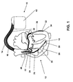
- Fig. 1 shows an implant 10 in the form of a biventricular three-chamber pacemaker and cardioverter / defibrillator (ICD).
- ICD cardioverter / defibrillator
- the right atrial electrode lead 14 has a right atrial tip electrode 22 at its distal end and a right atrial ring electrode 24 a short distance away.
- the right ventricular lead 16 carries a right ventricular tip electrode 18 at its distal end and a right ventricular lead a little further away Ring electrode 20.
- a left ventricular tip electrode 34 and a little away from a left ventricular ring electrode 32 is attached. These electrodes are used to record electrical potentials in the respective heart chamber and the delivery of stimulation pulses to the respective heart chamber in normal pacemaker operation. This need not be explained at this point.
- the right-ventricular electrode lead 16 also carries a right ventricular right-ventricular shock coil 38 in the implanted state as a defibrillation electrode and a second shock coil 40 in the implanted state in the superior vena cava.
- a left-ventricular shock coil 36 is also attached to the left ventricular electrode lead 30. If needed, the shock coils serve as defibrillation electrodes for delivery of defibrillation shocks. Again, this need not be explained in detail here.
- FIG. 2 the main components of the heart stimulator 10 are shown.
- the electrical connections for the various electrodes 18, 20, 24, 22, 32, 34, 36, 38 and 40 are shown.
- Shock electrodes 38 and 40 and 36 are each connected to a right ventricular shock pulse generator 50 and SVC shock generator 52, respectively.
- Both shock generators 50 and 52 are connected to a pacing control unit 54 that drives the two shock pulse generators 50 and 52 as needed to generate and deliver a defibrillation shock.
- connection for the right-ventricular tip electrode RV tip and the connection for the right-ventricular ring electrode RV ring are each connected both to a right-ventricular stimulation unit 56 and to a right-ventricular sensing unit 58. Both the right ventricular pacing unit 56 and the right ventricular sensing unit 58 are each connected to the pacing control unit 54.
- the right-ventricular stimulation unit 56 is designed to generate a right-ventricular stimulation pulse in response to a control signal of the stimulation control unit 54, and subsequently to deliver the right-ventricular tip electrode RV tip for the right-ventricular ring electrode RV ring.
- the housing 42 of the heart stimulator 10 it is also possible for the housing 42 of the heart stimulator 10 to form a neutral electrode and the right-ventricular stimulation unit 56 to form the connection for the right-ventricular ring electrode RV Tip and the housing 42 is connected as another electrode for delivering a stimulation pulse.
- a right ventricular stimulation pulse differs from a defibrillation shock in that the stimulation pulse has a much lower pulse strength so that it does not excite the full heart tissue (myocardium) of a ventricle like a defibrillation shock at one go, but only the heart muscle cells in the immediate vicinity of the right ventricular tip electrode RV Tip 18. This excitation then spreads through natural conduction across the entire right ventricle 28, thus providing a stimulated contraction of the right ventricle 28.
- the right-ventricular sensing unit 58 is designed to initially amplify and filter electrical potential applied to the terminal for the right-ventricular ring electrode RV ring and the right-ventricular tip electrode RV Tip by means of an input amplifier. Furthermore, the right-ventricular sensing unit 58 is designed to evaluate the course of the electrical signals applied to its inputs in such a way that the right-ventricular sensing unit 58 automatically generates a natural (intrinsic), ie. H. automatic contraction of the right ventricle 28 detected. This can be done, for example, by comparing the course of the signal present at the inputs of the right-ventricular sensing unit 58 with a threshold value.
- the largest amplitude of the signal in the form of the so-called R-wave is indicative of a natural contraction of the right ventricle 28, which can be detected by threshold comparison.
- the right ventricular sensing unit 58 then outputs a corresponding output signal indicative of natural contraction of the right ventricle 28 to the pacing control unit 54.
- connection for the right atrial tip electrode RA Tip and the connection for the right atrial ring electrode RA ring are connected both to a right atrial stimulation unit 60 and to a right atrial sensing unit 62, each of which in turn is connected to the stimulation control unit 54.
- the right atrial stimulation unit 60 is designed to generate stimulation pulses whose strength is sufficient to excite the right atrial myocardium.
- the right-atrial stimulation pulses may have a different pulse strength than the right-ventricular stimulation pulses.
- the right-atrial sensing unit 62 is designed to detect a so-called P-wave from the profile of the differential signal applied to its inputs, which characterizes a natural (intrinsic) contraction of the right atrium 26. If the right atrial sensing unit 62 detects a corresponding P-wave, it generates an output signal and passes it on to the stimulation control unit 54, which identifies a natural contraction of the right atrium 26.
- left ventricle tip LV terminal LV Tip and the left ventricular ring LV ring terminal LV are also connected to a left ventricular pacing unit 64 and a left ventricular sensing unit 66.
- the left ventricular pacing unit 64 and the left ventricular sensing unit 66 are also connected to the pacing control unit 54. Both function similarly to the previously described stimulation units 56 and 60 and sensing units 58 and 62.
- an acceleration sensor 72 is connected to the stimulation control unit 54 and integrated into the housing 42 of the heart stimulator 10.
- the acceleration sensor 72 is designed to detect a movement signal dependent on the physical activity of a patient and to output a corresponding first accelerometer output signal, which indicates the physical activity of the patient, to the stimulation control unit 54. This allows the pacing control unit 54 to adjust the timing of the pacing pulses to the needs of the patient (hemodynamic needs).
- the heart stimulator 10 comprises a memory unit 80, which is connected to the stimulation control unit 54 and allows signals generated or evaluated by the stimulation control unit 54 to be stored.
- the memory unit 80 allows control programs for the stimulation control unit 54 to be stored in changeable form.
- the stimulation control unit 54 is connected to a timer 82.
- the memory unit 80 is connected to a telemetry unit 84 which allows data stored in the memory unit 80 to be wirelessly transmitted to an external device or to transmit programming commands from the external device to the heart stimulator 10 and stored in the memory unit 80.
- FIG. 3 shows the relevant to the invention components of the heart stimulator 10, namely the right atrial sensing unit 62, the right ventricular sensing unit 58 and the Stimulation control unit 54 in a detailed representation, this unit, in particular the stimulation control unit 54, even more components than those in FIG. 3 have shown or may have.
- the right-atrial sensing unit 62 and the right ventricle sensing unit 54 are each connected to a connection 110 for an atrial and a ventricular electrode and each have a blanking stage 120 and an amplifier 130 each, which are respectively connected in series to the respective electrode terminal 110.
- the respective blanking stage 120 serves in a known manner for the suppression of stimulation artifacts after delivery of a stimulation pulse.
- the intracardiac signals derived by means of the atrial or ventricular electrode are first amplified.
- the respective amplifier 130 is followed in each case by an A / D converter and filter stage 140, which digitizes and filters the signal.
- the A / D converter and filter stage 140 is followed in each case by a comparator 150, which compares the digitized and filtered signal with a threshold value in each case in order to detect P-waves by threshold value comparison in the case of the intra-atrial signal and by threshold value comparisons in the case of the intraventricular signal To detect R-waves.
- the right atrial sensing unit 62 and the right ventricular sensing unit 58 are each capable of producing a right atrial and a right ventricular sense signal, respectively, if there is a contraction of the respective ventricle.
- the P and R-wave synchronous events (sense signals) thus obtained are supplied to the stimulation control unit 54 and evaluated there by an interval measuring unit 160 with regard to the intervals occurring between them.
- These PP, PR, RP and RR intervals thus obtained are applied to a pacing timer 180 for controlling the antibradycardic pacing. Further, this interval information is compared in an interval evaluation unit 170 for discriminating between VT and SVT in terms of their atrial and ventricular rhythm relationships and made available in evaluated form to a detection and therapy control unit 190 for antitachycardiac therapy (ATP, shock).
- ATP antitachycardiac therapy
- the heart stimulator as part of the stimulation control unit 54 additionally has an evaluation unit 200 for tachycardia discrimination, which is connected to the interval measuring unit 160 and the detection and therapy control unit 190 and which is designed to generate an ATP response signal.
- the evaluation unit 200 evaluates the intervals determined in the interval measuring unit 160 immediately before and during an ATP. For this purpose, there is a bidirectional connection between the evaluation unit 200 and the therapy control unit 190.
- the evaluation unit 200 is informed by the therapy control unit 190 about the impending release of ATP and, in turn, influences the therapy control unit 190 with the respectively obtained ATP response signal.
- the evaluation is designed such that by interpolation those atrial intervals are replaced, which were possibly hidden by a cross-blank during ventricular ATP.
- the following illustrations show possible sequences for the therapy drain control by the therapy control unit 190 as a function of the ATP response signal.
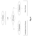
- the Figure 4 shows a simple extension of the therapy procedure control by means of the ATP response signal:
- the programmed antitachycardic stimulation is initially delivered and at the same time determines the ATP response signal. If the atrial rhythm is modulated by the ventricular ATP, the ATP follows a programmed ventricular shock therapy after fulfilled VT redetection, otherwise no shock therapy is released despite satisfied redetection since in this case the initial VT classification is in favor of an SVT due to the ATP response signal was corrected.
- FIG. 5 An alternative implementation is in Figure 5 shown here: After initial VT detection, an ATP and simultaneous analysis of the ATP response signal is performed. If a new VT redetection is fulfilled after the ATP, either a ventricular shock therapy is given off depending on the ATP response signal or the VT / SVT discrimination is restarted. Thus, it is possible to ensure a short redetection time between ATP and shock therapy and only in case of "doubtful" VT classification to start a prolonged redetection with extended discrimination criteria (eg extended detection counter).
- extended discrimination criteria eg extended detection counter
- FIG. 6 Another variant of the implementation shows FIG. 6 :
- an ATP response signal representing an SVT it is decided after redetection whether the atrial arrhythmia is stable or unstable and initiates atrial therapy (RF burst or cardioversion shock) in the case of atrial fibrillation (unstable). On the other hand, if the atrial rhythm is stable, no therapy is delivered (load-induced increase in frequency).
Landscapes
- Health & Medical Sciences (AREA)
- Cardiology (AREA)
- Heart & Thoracic Surgery (AREA)
- Engineering & Computer Science (AREA)
- Biomedical Technology (AREA)
- Nuclear Medicine, Radiotherapy & Molecular Imaging (AREA)
- Radiology & Medical Imaging (AREA)
- Life Sciences & Earth Sciences (AREA)
- Animal Behavior & Ethology (AREA)
- General Health & Medical Sciences (AREA)
- Public Health (AREA)
- Veterinary Medicine (AREA)
- Electrotherapy Devices (AREA)
Applications Claiming Priority (1)
| Application Number | Priority Date | Filing Date | Title |
|---|---|---|---|
| DE102008020022A DE102008020022A1 (de) | 2008-04-22 | 2008-04-22 | Antitachykarder Herzstimulator |
Publications (3)
| Publication Number | Publication Date |
|---|---|
| EP2111892A2 true EP2111892A2 (fr) | 2009-10-28 |
| EP2111892A3 EP2111892A3 (fr) | 2012-01-11 |
| EP2111892B1 EP2111892B1 (fr) | 2014-04-16 |
Family
ID=40937595
Family Applications (1)
| Application Number | Title | Priority Date | Filing Date |
|---|---|---|---|
| EP09156052.4A Not-in-force EP2111892B1 (fr) | 2008-04-22 | 2009-03-24 | Stimulateur cardiaque contre la tachychardie |
Country Status (3)
| Country | Link |
|---|---|
| US (1) | US7983752B2 (fr) |
| EP (1) | EP2111892B1 (fr) |
| DE (1) | DE102008020022A1 (fr) |
Families Citing this family (6)
| Publication number | Priority date | Publication date | Assignee | Title |
|---|---|---|---|---|
| US8903490B2 (en) * | 2010-03-03 | 2014-12-02 | Cardiac Pacemakers, Inc. | Methods and systems for recognizing arrhythmias using neural stimulation |
| EP2510975A1 (fr) | 2011-04-14 | 2012-10-17 | BIOTRONIK SE & Co. KG | Stimulateur cardiaque |
| US9238143B2 (en) | 2011-05-10 | 2016-01-19 | Biotronik Se & Co. Kg | Implantable medical device with electrode fault detection |
| US8670825B2 (en) | 2012-07-31 | 2014-03-11 | Pacesetter, Inc. | Method and system for discrimination of VT and SVT arrhythmias |
| EP2826523B1 (fr) * | 2013-07-17 | 2015-08-19 | BIOTRONIK SE & Co. KG | Appareil thérapeutique cardiaque implantable |
| DE102019110286A1 (de) * | 2019-04-18 | 2020-10-22 | Biotronik Se & Co. Kg | Implantierbare Anordnung zur Stimulation eines menschlichen oder tierischen Herzens |
Citations (7)
| Publication number | Priority date | Publication date | Assignee | Title |
|---|---|---|---|---|
| US5144947A (en) | 1990-04-03 | 1992-09-08 | Telectronics Pacing Systems, Inc. | Apparatus and method for antitachycardia pacing in a arrhythmia control systems |
| US5686793A (en) | 1992-01-29 | 1997-11-11 | Fusion Uv Systems, Inc. | Excimer lamp with high pressure fill |
| US5891170A (en) | 1996-06-18 | 1999-04-06 | Ela Medical, S.A. | Method and apparatus for advanced tachyarrhythmia discrimination |
| US20040093037A1 (en) | 2002-09-04 | 2004-05-13 | Christine Henry | Discrimination between ventricular tachycardia and ventricular fibrillation in an active implantable medical device of the defibrillator, cardiovertor and/or antitachycardia pacemaker type |
| US6748269B2 (en) | 2001-10-17 | 2004-06-08 | Cardiac Pacemakers, Inc. | Algorithm for discrimination of 1:1 tachycardias |
| US6889080B2 (en) | 2000-11-27 | 2005-05-03 | Ela Medical S.A. | Discrimination of atrial fibrillations for an active implantable medical device, in particular a defibrillator/cardiovertor |
| US7149577B2 (en) | 2002-12-02 | 2006-12-12 | Medtronic, Inc. | Apparatus and method using ATP return cycle length for arrhythmia discrimination |
Family Cites Families (3)
| Publication number | Priority date | Publication date | Assignee | Title |
|---|---|---|---|---|
| US6978177B1 (en) * | 2000-11-14 | 2005-12-20 | Cardiac Pacemakers, Inc. | Method and apparatus for using atrial discrimination algorithms to determine optimal pacing therapy and therapy timing |
| US8010193B2 (en) * | 2002-11-20 | 2011-08-30 | University Of Pittsburgh-Of The Commonwealth System Of Higher Education | Device and method to discriminate between supraventricular tachycardias and ventricular arrhythmias |
| US7317942B2 (en) * | 2004-05-05 | 2008-01-08 | Medtronic, Inc. | Dynamic discrimination utilizing anti-tachy pacing therapy in an implantable medical device |
-
2008
- 2008-04-22 DE DE102008020022A patent/DE102008020022A1/de not_active Withdrawn
-
2009
- 2009-03-24 EP EP09156052.4A patent/EP2111892B1/fr not_active Not-in-force
- 2009-04-20 US US12/426,325 patent/US7983752B2/en not_active Expired - Fee Related
Patent Citations (8)
| Publication number | Priority date | Publication date | Assignee | Title |
|---|---|---|---|---|
| US5144947A (en) | 1990-04-03 | 1992-09-08 | Telectronics Pacing Systems, Inc. | Apparatus and method for antitachycardia pacing in a arrhythmia control systems |
| US5686793A (en) | 1992-01-29 | 1997-11-11 | Fusion Uv Systems, Inc. | Excimer lamp with high pressure fill |
| US5891170A (en) | 1996-06-18 | 1999-04-06 | Ela Medical, S.A. | Method and apparatus for advanced tachyarrhythmia discrimination |
| US6889080B2 (en) | 2000-11-27 | 2005-05-03 | Ela Medical S.A. | Discrimination of atrial fibrillations for an active implantable medical device, in particular a defibrillator/cardiovertor |
| US6748269B2 (en) | 2001-10-17 | 2004-06-08 | Cardiac Pacemakers, Inc. | Algorithm for discrimination of 1:1 tachycardias |
| US7174209B2 (en) | 2001-10-17 | 2007-02-06 | Cardiac Pacemakers, Inc. | Algorithm for discrimination of 1:1 tachycardias |
| US20040093037A1 (en) | 2002-09-04 | 2004-05-13 | Christine Henry | Discrimination between ventricular tachycardia and ventricular fibrillation in an active implantable medical device of the defibrillator, cardiovertor and/or antitachycardia pacemaker type |
| US7149577B2 (en) | 2002-12-02 | 2006-12-12 | Medtronic, Inc. | Apparatus and method using ATP return cycle length for arrhythmia discrimination |
Also Published As
| Publication number | Publication date |
|---|---|
| US20090264947A1 (en) | 2009-10-22 |
| EP2111892A3 (fr) | 2012-01-11 |
| DE102008020022A1 (de) | 2009-10-29 |
| US7983752B2 (en) | 2011-07-19 |
| EP2111892B1 (fr) | 2014-04-16 |
Similar Documents
| Publication | Publication Date | Title |
|---|---|---|
| EP1016434B1 (fr) | Stimulateur cardiaque | |
| DE69732553T2 (de) | Herzschrittmacher mit verbesserter Erfassung von atrialer Fibrillation | |
| DE69633957T2 (de) | Implantierbares Gerät zur Antitachykardierierung | |
| EP2353644B1 (fr) | Cardioverteur/défibrillateur et dispositif de traitement de signal pour la classification de signaux intra-cardiaux | |
| DE69324265T2 (de) | Apparat zur detektion und therapie von tachykardie und herzflimmern | |
| EP1510173B1 (fr) | Appareil de mesure d'impédances intracardiaques | |
| EP1106206B1 (fr) | Appareil de régulation de la fréquence et de l'action de pompage du coeur | |
| DE69326623T2 (de) | Apparat zur detektion und therapie von tachykardie und herzflimmern | |
| EP1762270B1 (fr) | Dispositif pour la détermination des paramètres cardiaques | |
| DE60020514T2 (de) | Verfahren zur Unterscheidung von im Herzen erfassten elektrischen Ereignissen und entsprechendes System | |
| DE60131041T2 (de) | Implantierbare Herzvorrichtung zur Überwachung der Verschlechterung oder Verbesserung von Herzerkrankungen | |
| EP2135640A1 (fr) | Dispositif d'électrothérapie destiné au traitement de défaillances du rythme tachycarde d'un cýur | |
| EP2540341B1 (fr) | Stimulateur cardiaque destiné à administrer un traitement de modulation de la contractilité cardiaque | |
| EP2111892B1 (fr) | Stimulateur cardiaque contre la tachychardie | |
| EP2676697B1 (fr) | Capteur de dislocation | |
| DE60031640T2 (de) | Vorrichtung zur Erkennung einer natürlichen elektrischen Kohärenz im Herz und zur Verabreichung einer darauf basierenden Therapie | |
| EP1302158B1 (fr) | Appareil de prédiction de tachyarythmie | |
| EP1774988A2 (fr) | Dispositif implantable pour la détermination des vecteurs cardiaques | |
| EP2422843B1 (fr) | Appareil de thérapie électronique implantable | |
| EP2111893A1 (fr) | Stimulateur cardiaque ventriculaire | |
| EP2140910B1 (fr) | Stimulateur cardiaque destiné au traitement des rythmes tachycardiques | |
| DE102008002293A1 (de) | Antitachykarder Herzstimulator | |
| EP2184009A2 (fr) | Stimulateur cardiaque à une chambre | |
| EP2826524B1 (fr) | Appareil de traitement cardiaque destiné à détecter des tachycardies ou fibrillations ventriculaires | |
| EP1812107B1 (fr) | Dispositif de prediction de tachyarythmies et/ou d'arythmies vestibulaires |
Legal Events
| Date | Code | Title | Description |
|---|---|---|---|
| PUAI | Public reference made under article 153(3) epc to a published international application that has entered the european phase |
Free format text: ORIGINAL CODE: 0009012 |
|
| AK | Designated contracting states |
Kind code of ref document: A2 Designated state(s): AT BE BG CH CY CZ DE DK EE ES FI FR GB GR HR HU IE IS IT LI LT LU LV MC MK MT NL NO PL PT RO SE SI SK TR |
|
| AX | Request for extension of the european patent |
Extension state: AL BA RS |
|
| PUAL | Search report despatched |
Free format text: ORIGINAL CODE: 0009013 |
|
| AK | Designated contracting states |
Kind code of ref document: A3 Designated state(s): AT BE BG CH CY CZ DE DK EE ES FI FR GB GR HR HU IE IS IT LI LT LU LV MC MK MT NL NO PL PT RO SE SI SK TR |
|
| AX | Request for extension of the european patent |
Extension state: AL BA RS |
|
| RIC1 | Information provided on ipc code assigned before grant |
Ipc: A61N 1/362 20060101AFI20111207BHEP |
|
| 17P | Request for examination filed |
Effective date: 20120620 |
|
| AKX | Designation fees paid |
Designated state(s): CH DE FR GB IE LI SE |
|
| GRAP | Despatch of communication of intention to grant a patent |
Free format text: ORIGINAL CODE: EPIDOSNIGR1 |
|
| INTG | Intention to grant announced |
Effective date: 20131121 |
|
| GRAP | Despatch of communication of intention to grant a patent |
Free format text: ORIGINAL CODE: EPIDOSNIGR1 |
|
| GRAS | Grant fee paid |
Free format text: ORIGINAL CODE: EPIDOSNIGR3 |
|
| INTG | Intention to grant announced |
Effective date: 20140211 |
|
| GRAA | (expected) grant |
Free format text: ORIGINAL CODE: 0009210 |
|
| AK | Designated contracting states |
Kind code of ref document: B1 Designated state(s): CH DE FR GB IE LI SE |
|
| REG | Reference to a national code |
Ref country code: GB Ref legal event code: FG4D Free format text: NOT ENGLISH |
|
| REG | Reference to a national code |
Ref country code: CH Ref legal event code: EP |
|
| REG | Reference to a national code |
Ref country code: IE Ref legal event code: FG4D Free format text: LANGUAGE OF EP DOCUMENT: GERMAN |
|
| REG | Reference to a national code |
Ref country code: DE Ref legal event code: R096 Ref document number: 502009009178 Country of ref document: DE Effective date: 20140605 |
|
| PG25 | Lapsed in a contracting state [announced via postgrant information from national office to epo] |
Ref country code: SE Free format text: LAPSE BECAUSE OF FAILURE TO SUBMIT A TRANSLATION OF THE DESCRIPTION OR TO PAY THE FEE WITHIN THE PRESCRIBED TIME-LIMIT Effective date: 20140416 |
|
| REG | Reference to a national code |
Ref country code: DE Ref legal event code: R097 Ref document number: 502009009178 Country of ref document: DE |
|
| PLBE | No opposition filed within time limit |
Free format text: ORIGINAL CODE: 0009261 |
|
| STAA | Information on the status of an ep patent application or granted ep patent |
Free format text: STATUS: NO OPPOSITION FILED WITHIN TIME LIMIT |
|
| 26N | No opposition filed |
Effective date: 20150119 |
|
| REG | Reference to a national code |
Ref country code: DE Ref legal event code: R097 Ref document number: 502009009178 Country of ref document: DE Effective date: 20150119 |
|
| REG | Reference to a national code |
Ref country code: DE Ref legal event code: R082 Ref document number: 502009009178 Country of ref document: DE Ref country code: DE Ref legal event code: R082 Ref document number: 502009009178 Country of ref document: DE Representative=s name: RANDOLL, SOEREN, DIPL.-CHEM. UNIV. DR. RER. NA, DE |
|
| GBPC | Gb: european patent ceased through non-payment of renewal fee |
Effective date: 20150324 |
|
| REG | Reference to a national code |
Ref country code: FR Ref legal event code: ST Effective date: 20151130 |
|
| PG25 | Lapsed in a contracting state [announced via postgrant information from national office to epo] |
Ref country code: GB Free format text: LAPSE BECAUSE OF NON-PAYMENT OF DUE FEES Effective date: 20150324 |
|
| PG25 | Lapsed in a contracting state [announced via postgrant information from national office to epo] |
Ref country code: FR Free format text: LAPSE BECAUSE OF NON-PAYMENT OF DUE FEES Effective date: 20150331 |
|
| REG | Reference to a national code |
Ref country code: DE Ref legal event code: R082 Ref document number: 502009009178 Country of ref document: DE Ref country code: DE Ref legal event code: R081 Ref document number: 502009009178 Country of ref document: DE Owner name: BIOTRONIK SE & CO. KG, DE Free format text: FORMER OWNER: BIOTRONIK CRM PATENT AG, BAAR, CH |
|
| PGFP | Annual fee paid to national office [announced via postgrant information from national office to epo] |
Ref country code: IE Payment date: 20220322 Year of fee payment: 14 Ref country code: DE Payment date: 20220317 Year of fee payment: 14 Ref country code: CH Payment date: 20220324 Year of fee payment: 14 |
|
| REG | Reference to a national code |
Ref country code: DE Ref legal event code: R119 Ref document number: 502009009178 Country of ref document: DE |
|
| REG | Reference to a national code |
Ref country code: CH Ref legal event code: PL |
|
| REG | Reference to a national code |
Ref country code: IE Ref legal event code: MM4A |
|
| PG25 | Lapsed in a contracting state [announced via postgrant information from national office to epo] |
Ref country code: LI Free format text: LAPSE BECAUSE OF NON-PAYMENT OF DUE FEES Effective date: 20230331 Ref country code: IE Free format text: LAPSE BECAUSE OF NON-PAYMENT OF DUE FEES Effective date: 20230324 Ref country code: DE Free format text: LAPSE BECAUSE OF NON-PAYMENT OF DUE FEES Effective date: 20231003 Ref country code: CH Free format text: LAPSE BECAUSE OF NON-PAYMENT OF DUE FEES Effective date: 20230331 |