EP2113053B1 - Compresseur et dispositif de séparation d'huile pour celui-ci - Google Patents
Compresseur et dispositif de séparation d'huile pour celui-ci Download PDFInfo
- Publication number
- EP2113053B1 EP2113053B1 EP07793785.2A EP07793785A EP2113053B1 EP 2113053 B1 EP2113053 B1 EP 2113053B1 EP 07793785 A EP07793785 A EP 07793785A EP 2113053 B1 EP2113053 B1 EP 2113053B1
- Authority
- EP
- European Patent Office
- Prior art keywords
- oil
- refrigerant
- compressor
- casing
- upper space
- Prior art date
- Legal status (The legal status is an assumption and is not a legal conclusion. Google has not performed a legal analysis and makes no representation as to the accuracy of the status listed.)
- Not-in-force
Links
- 239000003507 refrigerant Substances 0.000 claims description 68
- 230000006835 compression Effects 0.000 claims description 29
- 238000007906 compression Methods 0.000 claims description 29
- 238000000926 separation method Methods 0.000 claims description 7
- 230000005484 gravity Effects 0.000 claims 4
- 238000009434 installation Methods 0.000 description 4
- 239000012530 fluid Substances 0.000 description 3
- 238000004378 air conditioning Methods 0.000 description 2
- 230000000694 effects Effects 0.000 description 2
- 238000004519 manufacturing process Methods 0.000 description 2
- 238000012986 modification Methods 0.000 description 2
- 230000004048 modification Effects 0.000 description 2
- 230000003252 repetitive effect Effects 0.000 description 2
- 230000004888 barrier function Effects 0.000 description 1
- 238000010276 construction Methods 0.000 description 1
- 230000003247 decreasing effect Effects 0.000 description 1
- 230000007812 deficiency Effects 0.000 description 1
- 230000004907 flux Effects 0.000 description 1
- 230000006698 induction Effects 0.000 description 1
- 238000003780 insertion Methods 0.000 description 1
- 230000037431 insertion Effects 0.000 description 1
- 238000000034 method Methods 0.000 description 1
- 238000005057 refrigeration Methods 0.000 description 1
- 230000001360 synchronised effect Effects 0.000 description 1
Images



Classifications
-
- F—MECHANICAL ENGINEERING; LIGHTING; HEATING; WEAPONS; BLASTING
- F04—POSITIVE - DISPLACEMENT MACHINES FOR LIQUIDS; PUMPS FOR LIQUIDS OR ELASTIC FLUIDS
- F04C—ROTARY-PISTON, OR OSCILLATING-PISTON, POSITIVE-DISPLACEMENT MACHINES FOR LIQUIDS; ROTARY-PISTON, OR OSCILLATING-PISTON, POSITIVE-DISPLACEMENT PUMPS
- F04C18/00—Rotary-piston pumps specially adapted for elastic fluids
- F04C18/02—Rotary-piston pumps specially adapted for elastic fluids of arcuate-engagement type, i.e. with circular translatory movement of co-operating members, each member having the same number of teeth or tooth-equivalents
- F04C18/0207—Rotary-piston pumps specially adapted for elastic fluids of arcuate-engagement type, i.e. with circular translatory movement of co-operating members, each member having the same number of teeth or tooth-equivalents both members having co-operating elements in spiral form
- F04C18/0215—Rotary-piston pumps specially adapted for elastic fluids of arcuate-engagement type, i.e. with circular translatory movement of co-operating members, each member having the same number of teeth or tooth-equivalents both members having co-operating elements in spiral form where only one member is moving
-
- F—MECHANICAL ENGINEERING; LIGHTING; HEATING; WEAPONS; BLASTING
- F04—POSITIVE - DISPLACEMENT MACHINES FOR LIQUIDS; PUMPS FOR LIQUIDS OR ELASTIC FLUIDS
- F04C—ROTARY-PISTON, OR OSCILLATING-PISTON, POSITIVE-DISPLACEMENT MACHINES FOR LIQUIDS; ROTARY-PISTON, OR OSCILLATING-PISTON, POSITIVE-DISPLACEMENT PUMPS
- F04C23/00—Combinations of two or more pumps, each being of rotary-piston or oscillating-piston type, specially adapted for elastic fluids; Pumping installations specially adapted for elastic fluids; Multi-stage pumps specially adapted for elastic fluids
- F04C23/008—Hermetic pumps
-
- F—MECHANICAL ENGINEERING; LIGHTING; HEATING; WEAPONS; BLASTING
- F04—POSITIVE - DISPLACEMENT MACHINES FOR LIQUIDS; PUMPS FOR LIQUIDS OR ELASTIC FLUIDS
- F04C—ROTARY-PISTON, OR OSCILLATING-PISTON, POSITIVE-DISPLACEMENT MACHINES FOR LIQUIDS; ROTARY-PISTON, OR OSCILLATING-PISTON, POSITIVE-DISPLACEMENT PUMPS
- F04C29/00—Component parts, details or accessories of pumps or pumping installations, not provided for in groups F04C18/00 - F04C28/00
- F04C29/02—Lubrication; Lubricant separation
- F04C29/026—Lubricant separation
-
- F—MECHANICAL ENGINEERING; LIGHTING; HEATING; WEAPONS; BLASTING
- F04—POSITIVE - DISPLACEMENT MACHINES FOR LIQUIDS; PUMPS FOR LIQUIDS OR ELASTIC FLUIDS
- F04C—ROTARY-PISTON, OR OSCILLATING-PISTON, POSITIVE-DISPLACEMENT MACHINES FOR LIQUIDS; ROTARY-PISTON, OR OSCILLATING-PISTON, POSITIVE-DISPLACEMENT PUMPS
- F04C29/00—Component parts, details or accessories of pumps or pumping installations, not provided for in groups F04C18/00 - F04C28/00
- F04C29/04—Heating; Cooling; Heat insulation
- F04C29/045—Heating; Cooling; Heat insulation of the electric motor in hermetic pumps
-
- Y—GENERAL TAGGING OF NEW TECHNOLOGICAL DEVELOPMENTS; GENERAL TAGGING OF CROSS-SECTIONAL TECHNOLOGIES SPANNING OVER SEVERAL SECTIONS OF THE IPC; TECHNICAL SUBJECTS COVERED BY FORMER USPC CROSS-REFERENCE ART COLLECTIONS [XRACs] AND DIGESTS
- Y10—TECHNICAL SUBJECTS COVERED BY FORMER USPC
- Y10S—TECHNICAL SUBJECTS COVERED BY FORMER USPC CROSS-REFERENCE ART COLLECTIONS [XRACs] AND DIGESTS
- Y10S418/00—Rotary expansible chamber devices
- Y10S418/01—Non-working fluid separation
Definitions
- Compressors are known. However, they suffer from various disadvantages.
- a compressor is a device for converting mechanical energy into compression energy to compressor a fluid.
- Compressors are divided into several types including a reciprocating compressor, a rotary compressor, a vane compressor, and a scroll compressor according to the method of compressing the fluid.
- a scroll compressor may include a driving motor that generates a driving force in a hermetic casing, and a compression device that compresses a refrigerant by receiving the driving force generated by the driving motor.
- the compression device may include an orbiting scroll coupled to a driving shaft of the driving motor that performs an orbit motion with respect to a fixed scroll, thus forming a plurality of compression chambers. As the compression chambers move towards a center, a refrigerant is consecutively compressed and then discharged.
- a compressor having an oil separating device is provided which is capable of always maintaining a predetermined amount of oil in the compressor without additionally providing an oil separating device along the a refrigerating cycle system.
- a scroll compressor that includes the features of independent claim 1.
- a compressor and an oil separating device therefor are provided which are capable of always maintaining a predetermined amount of oil in the compressor without additionally providing an oil separating device along a refrigerating cycle system. This results in the refrigerating cycle system having simplified piping and the refrigerant discharged from the compressor having a constant pressure, thereby preventing a function of the refrigerating cycle system from being reduced.
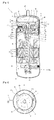
- FIGS. 1 to 5 are views showing a high pressure type scroll compressor having an oil separating device according an embodiment.
- a scroll compressor 1 may include a casing 10 containing a pre-determined amount of oil and hermetically maintained at a discharge pressure, a driving motor 20 disposed within the casing 10 that generates a rotational force, a compression device 30 disposed within the casing 10 that compresses a refrigerant by receiving the rotational force generated by the driving motor 20, and an oil separating device or unit 40 disposed at an outlet of the compression device 30 that separates a refrigerant and oil from each other.
- the casing 10 may include a body 11 having a cylindrical shape and having the driving motor 20 and the compression device 30 fixed at upper and lower portions of an inner circumferential surface thereof and an upper cap 12 and a lower cap 13 that seal upper and lower ends of the body 11.
- a refrigerant suction pipe SP may be coupled to an upper side of the body 11 so as to be directly coupled to an inlet 31c of a fixed scroll 31.
- a refrigerant discharge pipe DP may be connected to an upper center of the upper cap 12 so as to be connected to an upper space S1 of the casing 10.
- a main frame 14 and a sub frame 15 each having axial holes 14a and 15b that support the driving shaft 23 of the driving motor 20 may be fixed at inner upper and lower sides of the body 11.
- the axial hole 14a may be penetratingly formed at a center of the main frame 14, and an oil pocket 14b that collects oil sucked along the driving shaft 23 of the driving motor may be disposed at an upper end of the axial hole 14a.
- An oil collecting hole 14c that supplies oil stored in the oil pocket 14b to the casing 10 may be penetratingly formed on an outer circumferential surface of the oil pocket 14b.
- a first connection passage 14d through which a refrigerant and oil may be guided to a lower space S2 of the casing 10 by a guiding member 41 of the oil separating device 40 may be formed at one side at an outer circumferential surface of the main frame 14.
- a second connection passage 14e through which the refrigerant moved to the lower space S2 and oil not separated from the refrigerant may be moved to an upper space S 1 may be formed at another side at the outer circumferential surface of the main frame 14 that is not received by the guiding member 41.
- An oil collecting passage (not shown) through which oil separated from a refrigerant in the upper space S1 may be moved to the lower space S2 may be formed at one side at the outer circumferential surface of the main frame 14.
- the outer circumferential surface of the main frame 14 that is not covered by the guiding member 41 need not be sealed by the casing 10. Also, an oil collecting hole need not be additionally formed in the main frame 14.
- the oil separating device 40 may include separating member 42 in the form a pipe or tube that separates the refrigerant and oil coupled to one side of the outer circumferential surface of the main frame 14 not covered by the guiding member 41.
- the guiding member 41 may be disposed to cover an upper surface of a plate portion 31a of a fixed scroll 31 so as to hermetically cover a discharge port 31d of the fixed scroll 31 fixed to the casing 10 to form the compression device 30 together with an orbiting scroll 32.
- the guiding member 41 may have a fan shape so as to partially cover the casing 10 in a horizontal direction.
- An arc portion 41a may be adhered to an outer circumferential surface of the plate portion 31a of the fixed scroll 31, and a straight portion 41b opposite to the arc portion 41a may be adhered to an inner circumferential surface of the casing 10.
- the guiding member 41 may be hermetically coupled to an outer circumferential surface or an upper surface of the plate portion 31a of the fixed scroll 31 so that an inner space of the guiding member 41 may be sealed.
- An oil collecting through hole 41c that collects oil separated from a refrigerant at the upper space S1 of the casing 10 to the inner space of the guiding member 41 may be formed in an upper surface of the guiding member 41.
- the oil collecting through hole 41c may be formed to have a size small enough to be blocked by oil, thereby preventing refrigerant leakage.
- the separating member 42 may have a pipe shape with a constant diameter. As shown in FIG. 3 , the separating member 42 may have a pipe shape with a cross-sectional area A of an outlet being larger than a cross-sectional area B of an inlet so as to increase an orbiting speed of refrigerant and oil. As shown in FIG. 4 , the separating member 42 may have a pipe shape with a cross-sectional area A of the outlet being smaller than the cross-sectional area B of the inlet so as to decrease an orbiting speed of refrigerant and oil.
- the outlet of the separating member 42 may have a planar cross-sectional surface or an inclined cross-sectional surface.
- the inclined cross-sectional surface may be disposed to face an inner circumferential surface of the casing 10 so as to smoothly guide refrigerant and oil to the inner circumferential surface of the casing 10.
- the separating member 42 may be disposed along a plane and may be curved or bent on the plane so that refrigerant is directed to orbit in a clockwise direction or in a counterclockwise direction along the inner circumferential surface of the casing 10.
- the separating member 42 may be curved or bent on a second dimensional surface or plane or on a third dimensional surface or plane.
- a synchronous reluctance motor having a plurality of magnetic flux barriers at a rotor 22 may be used as the driving motor 20, as shown in FIG. 1 .
- an induction motor may be used also.
- the fixed scroll 31 may be formed so that a fixing wrap 31b forming a pair of compression chambers P may be formed at a lower surface of the plate portion 31a with an involute shape.
- a suction port 31c to which a refrigerant suction pipe SP may be directly connected may be formed at a side surface of the plate portion 31a.
- a discharge port 31d that discharges a compressed refrigerant to the upper space S1 of the casing 10 may be formed at a center of an upper surface of the plate portion 31a.
- a first connection hole 31e that guides discharged refrigerant and oil to the lower space S2 of the casing 10 may be formed in the plate portion 31a of the fixed scroll 31 that is covered by the guiding member 41.
- the first connection hole 31e may be connected to the first connection passage 14d of the main frame 14.
- a second connection hole 31f that guides a refrigerant having circulated through the lower space S2 of the casing 10 and oil not separated from the refrigerant to the upper space S1 is formed at the plate portion 31a of the fixed scroll 31 which is not covered by the guiding member 41.
- the second connection hole 31f may be connected to the second connection passage 14e of the main frame 14.
- the separating member 42 may be insertion-coupled to an outlet of the second connection hole 31f.
- a stepped surface that couples to the guiding member 41 may be formed on an outer circumferential surface of the plate portion 31a of the fixed scroll 31.
- the orbiting scroll 32 may be formed so that an orbiting wrap 32b forming a pair of compression chambers P together with the fixing wrap 31b of the fixed scroll 31 may be formed in an upper surface of a plate portion 32a with an involute shape.
- a boss portion 32c which may be coupled to the driving shaft 23 and which receives a driving force generated by the driving motor 20, may be formed at a center of a lower surface of the plate portion 32a.
- reference numeral 21 denotes a stator
- 23a denotes an oil passage
- 24 denotes an oil pump
- 33 denotes an Oldham's ring.
- the driving shaft 23 rotates together with the rotor 22 to transmit a rotational force to the orbiting scroll 32.
- the orbiting scroll 32 performs an orbiting motion on an upper surface of the main frame 14 due to the Oldham's ring 33.
- a pair of compression chambers P that consecutively move are formed between the fixing wrap 31b of the fixed scroll 31 and the orbiting wrap 32b of the orbiting scroll 32.
- the compression chambers P move towards the center to a decreased volume, thereby compressing a sucked refrigerant.
- An oil pump 24 disposed at a lower end of the driving shaft 23 pumps oil contained in the casing 10. The oil is sucked to an upper end of the driving shaft 23 through the oil passage 23a of the driving shaft 23. Some of the oil is supplied to the axial holes 14a and 15a of the main frame 14 and the sub frame 15, and some is dispersed from the upper end of the driving shaft 23 thus to be supplied to the compression chambers P via the oil pocket 14b of the main frame 14.
- the refrigerant and oil introduced into the compression chambers P move to the center of the compression chambers P, and are discharged through the discharge port 31d.
- the refrigerant and oil guided by the guiding member 41 move to the lower space S2 of the casing 10 through the first connection hole 31e of the fixed scroll 31 and the first connection passage 14d of the main frame 14.
- the refrigerant and oil circulate through the lower space S2 thus to cool the driving motor 20, and are discharged to the upper space S1 of the casing 10 through the second connection passage 14e of the main frame 14, the second connection hole 31f of the fixed scroll 31, and the separating member 42 coupled to the second connection hole 31f.
- the separating member 42 may be curved or bent along the inner circumferential surface of the casing 10, refrigerant and oil discharged from the separating member 42 performs an orbiting motion or circulates along the inner circumferential surface of the casing 10. In this way, the refrigerant and oil are separated from each other by a centrifugal force.
- the refrigerant moves to the refrigerating cycle system through the refrigerant discharge pipe DP, whereas the oil moves to the lower space S2 of the casing 10 via the oil collecting through hole 41c in the guiding member 41 or an oil collecting passage (not shown) of the main frame 14 to be collected.
- the oil separating device is provided in the compressor, a predetermined amount of oil is always maintained in the compressor without additionally installing an oil separating device along or in the refrigerating cycle system. Accordingly, the refrigerating cycle system has simplified piping and the refrigerant has constant pressure, thereby preventing a function of the refrigerating cycle system from being reduced.
- the scroll compressor may be constructed so that collected oil may be cooled outside the casing to lower a temperature of the oil. That is, shown in FIG. 6 , an oil collecting pipe 43 connected to the lower space S2 from the upper space S1 of the casing 10 may be disposed outside the casing 10. An inlet of the oil collecting pipe 43 may be connected to an upper side of the plate portion 31a of the fixed scroll 31, and an outlet of the oil collecting pipe 43 may be connected to a lower side of the sub frame 15. The outlet of the oil collecting pipe 43 may be connected between a lower side of the driving motor 20 and an upper side of the sub frame 15, or between a lower side of the main frame 14 and an upper side of the driving motor 20. A capillary tube or a capillary path 44 that lowers a temperature of collected oil may be disposed at a middle portion of the oil collecting pipe 43 outside the casing 10.
- refrigerant discharged from the compression chambers is guided to the driving motor by the guiding member.
- refrigerant discharged from the compression chamber is received in a guiding or receiving member having a cup shape, and then is guided to the upper space of the casing via a separating member in a pipe shape directly connected to the guiding or receiving member.
- the guiding or receiving member 41 that receives refrigerant discharged from the compression chambers may be formed at the plate portion 31a of the fixed scroll 31 by covering the discharge port 31d.
- the separating member 42 which discharges refrigerant discharged from the compression chambers P to the upper space of the casing, may be formed at the receiving member 41.
- an oil collecting passage F1 may be formed in the fixed scroll 31 and the main frame 14 so that oil separated from refrigerant by the oil separating device 40 may move to the lower space S2 of the casing 10. Further, an oil collecting pipe (not shown) may be installed to communicate with the oil collecting passage F1. As shown in FIG. 8 , when the refrigerant discharge pipe DP communicates with the lower space S2, refrigerant and oil separated from each other by the oil separating device 40 may be mixed with each other while moving to the lower space S2.
- a refrigerant circulating passage F2 may be relatively widely formed on outer circumferential surfaces of the fixed scroll 31 and the main frame 14.
- the oil collecting pipe 43 having the capillary tube or the capillary path 44 may be connected to outside of the casing 10 so that separated oil may move to the lower space S2 of the casing 10.
- the separating member may be formed to have a similar shape as those of FIGS. 2 to 4 .
- the separating member may be curved or bent so that oil may be separated from refrigerant by centrifugal force.
- the separating member 42 may be curved on the plane, as shown in FIG. 9 , or may be bent, as shown in FIG. 10 , so that refrigerant orbits or circulates in a clockwise direction or in a counterclockwise direction along the inner circumferential surface of the casing 10. Further, the separating member 42 may be curved or bent on a second dimensional surface or plane, or on a third dimensional surface or plane.
- the oil separating device 40 may include the cup-shaped guiding or receiving member 41 that receives the discharge port 31d of the fixed scroll 31, and the pipe-shaped separating member 42 and connected to the guiding or receiving member 41.
- the separating member 42 may be directly connected to the discharge port 31d of the fixed scroll 31.
- the separating member 42 may be formed so that an inlet and an outlet thereof may have the same diameter.
- the separating member 42 may be also formed so as to have a wide inlet and a narrow outlet and a backflow preventing valve (not shown) may be installed at the discharge port 31d of the fixed scroll 31.
- FIG. 11 shows an oil separating device according to another example not falling in the scope of the claims.
- the guiding member and separating member have been formed as one piece. That is, the separating member 42 may extend from the discharge part 31d of the fixed scroll 31.
- the separating member 42 may be shaped such that it directs refrigerant into the upper space S1 such that the refrigerant circulates in a spiral within the upper space S1. In this way, oil may be separated from refrigerant due to centrifugal force and may drain from the upper space S1 through oil collecting passage F1 formed in the fixed scroll 31.
- FIGS. 1 to 11 are applied to a high pressure type scroll compressor, an inner space of the casing of which is filled with a refrigerant at a discharge pressure.
- the embodiments and examples may be also applied to a lower pressure type scroll compressor, the inner space of the casing of which is divided into a suction space and a discharge space by a high/low pressure separating plate or a fixed scroll.
- an oil hole may be penetratingly formed in the high/low pressure separating plate or the fixed scroll, or oil separated from a refrigerant in the discharge space may be introduced into the suction space by an oil collecting pipe additionally installed to be connected to the discharge space and the suction space outside the casing.
- the low pressure type scroll compressor may have a similar construction to the high pressure type scroll compressor, and thus its details will be omitted.
- the compressor and oil separation device therefor has numerous applications in which compression of fluid is required, and in different types of compressors. Such applications may include, for example, air conditioning and refrigeration applications.
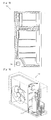
- FIG. 12 One such exemplary application is shown in FIG. 12 , in which a compressor 710 having an oil separation device according to embodiments disclosed herein is installed in a refrigerator/freezer 700. Installation and functionality of a compressor in a refrigerator is discussed in detail in U.S. Patent Nos. 7,082,776 , 6,955,064 , 7,114,345 , 7,055,338 , and 6,772,601 .
- FIG. 13 Another such exemplary application is shown in FIG. 13 , in which a compressor 810 having an oil separation device according to embodiments disclosed herein is installed in an outdoor unit of an air conditioner 800. Installation and functionality of a compressor in a refrigerator is discussed in detail in U.S. Patent Nos. 7,121,106 , 6,868,681 , 5,775,120 , 6,374,492 , 6,962,058 , 6,951,628 , and 5,947,373 .
- FIG. 14 Another such exemplary application is shown in FIG. 14 , in which a compressor 910 having an oil separation device according to embodiments disclosed herein is installed in a single, integrated air conditioning unit 900. Installation and functionality of a compressor in a refrigerator is discussed in detail in U.S. Patent Nos. 7,032,404 , 6,412,298 , 7,036,331 , 6,588,228 , 6,182,460 , and 5,775,123 .
- the scroll compressor according to the embodiments disclosed herein is provided with the oil separating device. Accordingly, a predetermined amount of oil is always maintained in the compressor without additionally installing the oil separating device in the refrigerating cycle system including the compressor. Accordingly, the refrigerating cycle system has simplified piping reducing fabrication costs, and the refrigerant has a constant pressure, preventing a function of the refrigerating cycle system from being lowered.
- any reference in this specification to "one embodiment,” “an embodiment,” “example embodiment,” etc. means that a particular feature, structure, or characteristic described in connection with the embodiment is included in at least one embodiment of the invention.
- the appearances of such phrases in various places in the specification are not necessarily all referring to the same embodiment.
Landscapes
- Engineering & Computer Science (AREA)
- Mechanical Engineering (AREA)
- General Engineering & Computer Science (AREA)
- Applications Or Details Of Rotary Compressors (AREA)
- Rotary Pumps (AREA)
Claims (13)
- Compresseur, comprenant :un carter (10) ;un dispositif de compression (30) pourvu d'une chambre de compression (P) disposée à l'intérieur du carter et prévue pour recevoir, comprimer et refouler un fluide frigorigène ; etun dispositif séparateur d'huile (40) disposé à l'intérieur d'un espace supérieur (S1) du carter, prévu pour faire circuler le fluide frigorigène et en séparer l'huile,caractérisé en ce que le dispositif séparateur d'huile comprend :un élément de guidage (41) prévu pour refouler le fluide frigorigène évacué du dispositif de compression ;un élément de séparation (42) prévu pour recevoir le fluide frigorigène de l'élément de guidage et refouler le fluide frigorigène dans une direction de circulation vers l'espace supérieur ; etun orifice de collecte d'huile (41c) en communication avec l'espace supérieur et prévu pour permettre à l'huile séparée par gravité du fluide frigorigène à l'intérieur de l'espace supérieur de s'écouler depuis l'espace supérieur par l'orifice de collecte d'huile,l'orifice de collecte d'huile étant ménagé dans une surface supérieure de l'élément de guidage.
- Compresseur selon la revendication 1, comprenant en outre un moteur d'entraînement (20) disposé à l'intérieur du carter et prévu pour entraîner le dispositif de compression, l'élément de guidage étant prévu pour refouler le fluide frigorigène évacué du dispositif de compression vers le moteur d'entraînement pour refroidir le moteur.
- Compresseur selon la revendication 2, où le dispositif séparateur d'huile comprend en outre un passage guidant le fluide frigorigène vers le moteur et/ou autour de celui-ci.
- Compresseur selon la revendication 1, où une sortie de l'élément de séparation est disposée au-dessus d'une surface supérieure de l'élément de guidage.
- Compresseur selon la revendication 1, où une entrée et une sortie de l'élément de séparation ont différentes surfaces de section transversale.
- Compresseur selon la revendication 1, où le dispositif séparateur d'huile est prévu pour faire circuler le fluide frigorigène évacué de la chambre de compression pour séparer par gravité l'huile du fluide frigorigène.
- Compresseur selon la revendication 1, où l'espace supérieur est disposé à l'intérieur du carter de manière adjacente à un conduit d'évacuation (DP) qui évacue le fluide frigorigène du carter.
- Compresseur selon la revendication 1, où l'élément de séparation comprend un tuyau qui reçoit le fluide frigorigène et refoule le fluide frigorigène vers l'espace supérieur.
- Compresseur selon la revendication 8, où le tuyau est cintré ou coudé.
- Compresseur selon la revendication 1, comprenant en outre un conduit collecteur d'huile (43), l'huile séparée par gravité du fluide frigorigène à l'intérieur de l'espace supérieur étant collectée pour être recyclée par l'orifice de collecte d'huile communiquant avec l'espace supérieur,
l'huile étant séparée par gravité du fluide frigorigène à l'intérieur de l'espace supérieur et s'écoulant de celui-ci par le conduit collecteur d'huile vers un espace inférieur (S2) du carter pour recyclage. - Compresseur selon la revendication 10, comprenant en outre un tuyau capillaire (44) monté sur le conduit collecteur d'huile.
- Compresseur selon la revendication 1, où l'élément de guidage et l'élément de séparation sont formés d'un seul tenant.
- Compresseur selon la revendication 1, où l'élément de séparation est prévu pour refouler le fluide frigorigène dans l'espace supérieur de manière à faire circuler le fluide frigorigène en spirale dans l'espace supérieur.
Applications Claiming Priority (3)
| Application Number | Priority Date | Filing Date | Title |
|---|---|---|---|
| KR1020070004553A KR100882480B1 (ko) | 2007-01-15 | 2007-01-15 | 스크롤 압축기 |
| KR1020070004554A KR100869928B1 (ko) | 2007-01-15 | 2007-01-15 | 스크롤 압축기 |
| PCT/KR2007/004215 WO2008088111A1 (fr) | 2007-01-15 | 2007-08-31 | Compresseur et dispositif de séparation d'huile pour celui-ci |
Publications (3)
| Publication Number | Publication Date |
|---|---|
| EP2113053A1 EP2113053A1 (fr) | 2009-11-04 |
| EP2113053A4 EP2113053A4 (fr) | 2011-11-23 |
| EP2113053B1 true EP2113053B1 (fr) | 2015-08-19 |
Family
ID=39617933
Family Applications (1)
| Application Number | Title | Priority Date | Filing Date |
|---|---|---|---|
| EP07793785.2A Not-in-force EP2113053B1 (fr) | 2007-01-15 | 2007-08-31 | Compresseur et dispositif de séparation d'huile pour celui-ci |
Country Status (3)
| Country | Link |
|---|---|
| US (1) | US7862313B2 (fr) |
| EP (1) | EP2113053B1 (fr) |
| WO (1) | WO2008088111A1 (fr) |
Families Citing this family (15)
| Publication number | Priority date | Publication date | Assignee | Title |
|---|---|---|---|---|
| DE102008036317A1 (de) * | 2008-07-29 | 2010-02-25 | Bitzer Kühlmaschinenbau Gmbh | Schraubenverdichter |
| US7980093B2 (en) * | 2009-09-25 | 2011-07-19 | Whirlpool Corporation | Combined refrigerant compressor and secondary liquid coolant pump |
| EP2530320B1 (fr) * | 2010-01-27 | 2019-09-04 | Daikin Industries, Ltd. | Compresseur et dispositif de réfrigération |
| US9109598B2 (en) * | 2011-03-18 | 2015-08-18 | Panasonic Intellectual Property Management Co., Ltd. | Compressor with oil separating mechanism |
| JP5039869B1 (ja) * | 2011-03-18 | 2012-10-03 | パナソニック株式会社 | 圧縮機 |
| CN103534487B (zh) * | 2011-05-16 | 2016-08-17 | 松下电器产业株式会社 | 压缩机 |
| JP5360258B2 (ja) * | 2012-04-04 | 2013-12-04 | パナソニック株式会社 | 圧縮機 |
| US9964122B2 (en) * | 2012-04-30 | 2018-05-08 | Emerson Climate Technologies, Inc. | Compressor staking arrangement and method |
| KR102226456B1 (ko) | 2014-08-07 | 2021-03-11 | 엘지전자 주식회사 | 압축기 |
| BE1022091B1 (nl) * | 2014-08-14 | 2016-02-15 | Atlas Copco Airpower Naamloze Vennootschap | Spiraalcompressor |
| KR101681590B1 (ko) | 2015-09-09 | 2016-12-01 | 엘지전자 주식회사 | 스크롤 압축기 |
| KR102481266B1 (ko) | 2016-04-26 | 2022-12-26 | 엘지전자 주식회사 | 스크롤 압축기 |
| CN110691911B (zh) * | 2017-06-06 | 2022-01-04 | 三菱电机株式会社 | 涡旋压缩机及制冷循环装置 |
| WO2020108224A1 (fr) * | 2018-11-29 | 2020-06-04 | 艾默生环境优化技术(苏州)有限公司 | Compresseur à spirale ayant une structure d'interception d'huile étanche |
| JP2021014812A (ja) * | 2019-07-11 | 2021-02-12 | ダイキン工業株式会社 | 圧縮機及び冷凍装置 |
Family Cites Families (82)
| Publication number | Priority date | Publication date | Assignee | Title |
|---|---|---|---|---|
| US3922114A (en) * | 1974-07-19 | 1975-11-25 | Dunham Bush Inc | Hermetic rotary helical screw compressor with improved oil management |
| JPS55107093A (en) * | 1979-02-13 | 1980-08-16 | Hitachi Ltd | Enclosed type scroll compressor |
| JPS62135693A (ja) * | 1985-12-09 | 1987-06-18 | Matsushita Refrig Co | 回転式圧縮機 |
| JPS62203992A (ja) * | 1986-03-03 | 1987-09-08 | Hitachi Ltd | 密閉形スクロ−ル圧縮機 |
| JPS62298679A (ja) | 1986-06-19 | 1987-12-25 | Toshiba Corp | スクロ−ル形圧縮機 |
| US5219281A (en) * | 1986-08-22 | 1993-06-15 | Copeland Corporation | Fluid compressor with liquid separating baffle overlying the inlet port |
| JPS63192985A (ja) | 1987-02-03 | 1988-08-10 | Matsushita Refrig Co | 回転式圧縮機 |
| JPH06100185B2 (ja) * | 1987-07-10 | 1994-12-12 | 株式会社日立製作所 | スクロ−ル圧縮機 |
| US4898520A (en) | 1988-07-18 | 1990-02-06 | United Technologies Corporation | Method of and arrangement for reducing bearing loads in scroll compressors |
| JPH06100186B2 (ja) | 1988-11-25 | 1994-12-12 | ダイキン工業株式会社 | スクロール型流体装置 |
| JP2782858B2 (ja) * | 1989-10-31 | 1998-08-06 | 松下電器産業株式会社 | スクロール気体圧縮機 |
| JP2558896B2 (ja) | 1989-11-17 | 1996-11-27 | 松下電器産業株式会社 | スクロール圧縮機 |
| KR920002931A (ko) * | 1990-07-31 | 1992-02-28 | 강진구 | 밀폐형 스크로울 압축기의 급유조절장치 |
| JPH05149274A (ja) | 1991-11-26 | 1993-06-15 | Toshiba Corp | スクロール式圧縮機 |
| JPH062680A (ja) * | 1992-06-17 | 1994-01-11 | Mitsubishi Heavy Ind Ltd | 密閉型電動圧縮機 |
| US5310326A (en) * | 1992-09-14 | 1994-05-10 | Mainstream Engineering Corporation | Rotary compressor with improved bore configuration and lubrication system |
| JP3257847B2 (ja) | 1993-02-10 | 2002-02-18 | 三菱電機株式会社 | 圧縮機の給油装置 |
| JPH0754788A (ja) * | 1993-08-09 | 1995-02-28 | Hitachi Ltd | 密閉形圧縮機 |
| US5370513A (en) * | 1993-11-03 | 1994-12-06 | Copeland Corporation | Scroll compressor oil circulation system |
| JP3391072B2 (ja) * | 1993-12-28 | 2003-03-31 | 松下電器産業株式会社 | 密閉型スクロール圧縮機 |
| US5591018A (en) * | 1993-12-28 | 1997-01-07 | Matsushita Electric Industrial Co., Ltd. | Hermetic scroll compressor having a pumped fluid motor cooling means and an oil collection pan |
| JPH07332265A (ja) | 1994-06-10 | 1995-12-22 | Hitachi Ltd | 密閉形スクロール圧縮機 |
| JPH08151990A (ja) * | 1994-11-30 | 1996-06-11 | Daikin Ind Ltd | スクロール型流体装置 |
| JP2718388B2 (ja) | 1995-02-07 | 1998-02-25 | 三菱電機株式会社 | スクロール型圧縮機 |
| US5533875A (en) * | 1995-04-07 | 1996-07-09 | American Standard Inc. | Scroll compressor having a frame and open sleeve for controlling gas and lubricant flow |
| JP3081955B2 (ja) * | 1995-08-23 | 2000-08-28 | 三洋電機株式会社 | 空気調和機 |
| US5775120A (en) * | 1995-09-14 | 1998-07-07 | Daikin Industries, Ltd. | Compact air conditioner outdoor unit having high heat exchanging ability |
| JPH09112474A (ja) * | 1995-10-17 | 1997-05-02 | Daikin Ind Ltd | 冷媒圧縮機 |
| JPH09170581A (ja) * | 1995-12-19 | 1997-06-30 | Daikin Ind Ltd | 圧縮機 |
| US5947373A (en) * | 1996-02-09 | 1999-09-07 | Sanyo Electric Co., Ltd. | Refrigerant circuit with fluid heated refrigerant |
| JPH10205466A (ja) | 1997-01-23 | 1998-08-04 | Mitsubishi Heavy Ind Ltd | スクロール型流体機械 |
| JP2984640B2 (ja) * | 1997-12-18 | 1999-11-29 | 三菱重工業株式会社 | 密閉型スクロール圧縮機 |
| US6301776B1 (en) * | 1998-05-15 | 2001-10-16 | Samsung Electronics Co., Ltd. | System and method for assembling an outdoor unit of a dual-unit type air conditioner |
| US6149413A (en) * | 1998-07-13 | 2000-11-21 | Carrier Corporation | Scroll compressor with lubrication of seals in back pressure chamber |
| US6182460B1 (en) * | 1998-08-26 | 2001-02-06 | Carrier Corporation | Window room air conditioner |
| KR20000026721A (ko) | 1998-10-22 | 2000-05-15 | 전주범 | 스크롤 압축기 |
| KR100332780B1 (ko) | 1999-10-01 | 2002-04-18 | 구자홍 | 저압식 스크롤 압축기의 과열 방지장치 |
| KR20010057497A (ko) | 1999-12-23 | 2001-07-04 | 구자홍 | 스크롤 압축기의 압축실 과열 방지장치 |
| KR100312780B1 (ko) | 1999-12-30 | 2001-11-03 | 신영주 | 압축기 내장형 오일분리기 |
| JP4637987B2 (ja) | 2000-01-25 | 2011-02-23 | 三菱重工業株式会社 | スクロール型圧縮機 |
| US6386840B1 (en) * | 2000-02-04 | 2002-05-14 | Scroll Technologies | Oil return for reduced height scroll compressor |
| US6309198B1 (en) * | 2000-02-24 | 2001-10-30 | Scroll Technologies | Scroll compressor with improved oil flow |
| US6412298B2 (en) * | 2000-04-29 | 2002-07-02 | Lg Electronics Inc. | Window type air conditioner |
| JP3750048B2 (ja) | 2000-05-22 | 2006-03-01 | 株式会社日立製作所 | スクロール圧縮機 |
| JP3760748B2 (ja) * | 2000-09-20 | 2006-03-29 | 株式会社日立製作所 | 密閉形電動圧縮機 |
| JP4502347B2 (ja) * | 2000-11-06 | 2010-07-14 | 日立アプライアンス株式会社 | スクリュー圧縮機 |
| JP2002138961A (ja) | 2000-11-06 | 2002-05-17 | Fujitsu General Ltd | 密閉型圧縮機 |
| US6527085B1 (en) * | 2000-11-14 | 2003-03-04 | Tecumseh Products Company | Lubricating system for compressor |
| US6422843B1 (en) * | 2001-02-13 | 2002-07-23 | Scroll Technologies | Oil supply cross-hole in orbiting scroll member |
| DE60230598D1 (de) * | 2001-04-07 | 2009-02-12 | Lg Electronics Inc | Vorrichtung und verfahren zur steuerung eines kaltluftkreislaufs in einer kühlvorrichtung |
| JP2003003974A (ja) | 2001-06-20 | 2003-01-08 | Fujitsu General Ltd | スクロール圧縮機 |
| JP2003021060A (ja) | 2001-07-10 | 2003-01-24 | Toyota Industries Corp | 圧縮機、圧縮機のバランス取り方法及び治具 |
| DE10147947C1 (de) * | 2001-09-28 | 2003-04-24 | Siemens Ag | Verfahren zur Herstellung eines Streustrahlenrasters oder Kollimators |
| FR2830292B1 (fr) * | 2001-09-28 | 2003-12-19 | Danfoss Maneurop S A | Circuit de gaz basse pression pour un compresseur |
| KR100441000B1 (ko) * | 2001-11-08 | 2004-07-21 | 삼성전자주식회사 | 팬케이싱을 갖춘 일체형 공기조화기 |
| JP3982238B2 (ja) * | 2001-11-08 | 2007-09-26 | 三菱電機株式会社 | 圧縮機 |
| KR100423970B1 (ko) * | 2001-11-24 | 2004-03-22 | 삼성전자주식회사 | 공기조화기 및 그 제어방법 |
| JP3832369B2 (ja) * | 2002-03-28 | 2006-10-11 | ダイキン工業株式会社 | 高低圧ドーム型圧縮機 |
| JP2003293955A (ja) | 2002-04-01 | 2003-10-15 | Daikin Ind Ltd | 圧縮機 |
| JP2003328963A (ja) * | 2002-05-16 | 2003-11-19 | Daikin Ind Ltd | スクロール型圧縮機 |
| KR20030089819A (ko) * | 2002-05-20 | 2003-11-28 | 엘지전자 주식회사 | 냉장고 기계실 커버 |
| JP4146693B2 (ja) | 2002-09-13 | 2008-09-10 | 日立アプライアンス株式会社 | スクロール圧縮機 |
| DE10248926B4 (de) * | 2002-10-15 | 2004-11-11 | Bitzer Kühlmaschinenbau Gmbh | Kompressor |
| EP1422483B1 (fr) * | 2002-11-21 | 2015-10-14 | LG Electronics Inc. | Appareil de conditionnement d'air |
| US7032404B2 (en) * | 2003-01-24 | 2006-04-25 | Lg Electronics Inc. | Air conditioner |
| KR100512677B1 (ko) * | 2003-02-21 | 2005-09-07 | 삼성전자주식회사 | 냉장고 |
| US7311501B2 (en) * | 2003-02-27 | 2007-12-25 | American Standard International Inc. | Scroll compressor with bifurcated flow pattern |
| US6772601B1 (en) * | 2003-03-12 | 2004-08-10 | Maytag Corporation | Temperature control system for a refrigerated compartment |
| KR20050019591A (ko) * | 2003-08-20 | 2005-03-03 | 삼성전자주식회사 | 응축기 케이싱을 구비한 일체형 공기조화기 |
| EP1524484A1 (fr) * | 2003-10-16 | 2005-04-20 | Whirlpool Corporation | Réfrigérateur |
| KR100548488B1 (ko) | 2003-12-19 | 2006-02-02 | 엘지전자 주식회사 | 스크롤압축기의 오일 공급구조 |
| JP4454318B2 (ja) | 2004-01-08 | 2010-04-21 | 三洋電機株式会社 | 圧縮機 |
| JP4067497B2 (ja) * | 2004-01-15 | 2008-03-26 | 株式会社デンソー | スクロール型圧縮機 |
| KR100547334B1 (ko) * | 2004-02-10 | 2006-01-26 | 엘지전자 주식회사 | 에어컨의 파이프 구조 |
| JP2005337142A (ja) * | 2004-05-27 | 2005-12-08 | Sanden Corp | 圧縮機 |
| US8300132B2 (en) * | 2004-07-23 | 2012-10-30 | Sony Corporation | Driving method of solid-state imaging device, solid-state imaging system, and camera system |
| KR100619741B1 (ko) * | 2004-09-13 | 2006-09-12 | 엘지전자 주식회사 | 오일토출 저감기능을 구비한 고압식 스크롤 압축기 |
| JP2006097495A (ja) * | 2004-09-28 | 2006-04-13 | Sanden Corp | 圧縮機 |
| KR100575815B1 (ko) * | 2004-12-10 | 2006-05-03 | 엘지전자 주식회사 | 스크롤 압축기의 유토출 저감 장치 |
| JP4192158B2 (ja) * | 2005-03-24 | 2008-12-03 | 日立アプライアンス株式会社 | 密閉形スクロール圧縮機及び冷凍空調装置 |
| KR100724387B1 (ko) * | 2005-09-28 | 2007-06-04 | 엘지전자 주식회사 | 밀폐형 압축기의 오일 펌핑 장치 |
| JP6100186B2 (ja) * | 2014-03-07 | 2017-03-22 | 悟 森下 | ガスメータ |
-
2007
- 2007-08-31 EP EP07793785.2A patent/EP2113053B1/fr not_active Not-in-force
- 2007-08-31 WO PCT/KR2007/004215 patent/WO2008088111A1/fr not_active Ceased
- 2007-11-01 US US11/933,534 patent/US7862313B2/en not_active Expired - Fee Related
Also Published As
| Publication number | Publication date |
|---|---|
| EP2113053A4 (fr) | 2011-11-23 |
| WO2008088111A1 (fr) | 2008-07-24 |
| EP2113053A1 (fr) | 2009-11-04 |
| US20080170957A1 (en) | 2008-07-17 |
| US7862313B2 (en) | 2011-01-04 |
Similar Documents
| Publication | Publication Date | Title |
|---|---|---|
| EP2113053B1 (fr) | Compresseur et dispositif de séparation d'huile pour celui-ci | |
| US7473083B2 (en) | Oil separating device for compressor | |
| EP2129917B1 (fr) | Compresseur et don dispositif de séparation d'huile | |
| EP2115302B1 (fr) | Compresseur et dispositif de blocage d'huile pour celui-ci | |
| US8992191B2 (en) | Scroll compressor with differential pressure hole | |
| US10890186B2 (en) | Compressor | |
| US10648471B2 (en) | Scroll compressor | |
| CN110118180B (zh) | 涡旋压缩机 | |
| EP2187059B1 (fr) | Compresseur hermétique et dispositif de cycle de réfrigération en disposant | |
| WO2018049057A1 (fr) | Compresseur | |
| US10605243B2 (en) | Scroll compressor with oil management system | |
| EP2187060B1 (fr) | Compresseur hermétique et dispositif de cycle de réfrigération en disposant | |
| US8221101B2 (en) | Scroll compressor with discharge guide | |
| US8734142B2 (en) | Rotation preventing member of a scroll compressor | |
| KR100882480B1 (ko) | 스크롤 압축기 | |
| JP2010196630A (ja) | 圧縮機 | |
| KR20080067262A (ko) | 스크롤 압축기 |
Legal Events
| Date | Code | Title | Description |
|---|---|---|---|
| PUAI | Public reference made under article 153(3) epc to a published international application that has entered the european phase |
Free format text: ORIGINAL CODE: 0009012 |
|
| 17P | Request for examination filed |
Effective date: 20090806 |
|
| AK | Designated contracting states |
Kind code of ref document: A1 Designated state(s): AT BE BG CH CY CZ DE DK EE ES FI FR GB GR HU IE IS IT LI LT LU LV MC MT NL PL PT RO SE SI SK TR |
|
| DAX | Request for extension of the european patent (deleted) | ||
| A4 | Supplementary search report drawn up and despatched |
Effective date: 20111024 |
|
| RIC1 | Information provided on ipc code assigned before grant |
Ipc: F04C 23/00 20060101ALI20111019BHEP Ipc: F04C 29/02 20060101ALI20111019BHEP Ipc: F04C 29/04 20060101ALI20111019BHEP Ipc: F04C 18/02 20060101AFI20111019BHEP |
|
| GRAP | Despatch of communication of intention to grant a patent |
Free format text: ORIGINAL CODE: EPIDOSNIGR1 |
|
| RIC1 | Information provided on ipc code assigned before grant |
Ipc: F04C 23/00 20060101ALI20150219BHEP Ipc: F04C 29/02 20060101ALI20150219BHEP Ipc: F04C 29/04 20060101ALI20150219BHEP Ipc: F04C 18/02 20060101AFI20150219BHEP |
|
| INTG | Intention to grant announced |
Effective date: 20150318 |
|
| GRAS | Grant fee paid |
Free format text: ORIGINAL CODE: EPIDOSNIGR3 |
|
| GRAA | (expected) grant |
Free format text: ORIGINAL CODE: 0009210 |
|
| AK | Designated contracting states |
Kind code of ref document: B1 Designated state(s): AT BE BG CH CY CZ DE DK EE ES FI FR GB GR HU IE IS IT LI LT LU LV MC MT NL PL PT RO SE SI SK TR |
|
| REG | Reference to a national code |
Ref country code: GB Ref legal event code: FG4D |
|
| REG | Reference to a national code |
Ref country code: CH Ref legal event code: EP |
|
| REG | Reference to a national code |
Ref country code: IE Ref legal event code: FG4D |
|
| REG | Reference to a national code |
Ref country code: AT Ref legal event code: REF Ref document number: 744032 Country of ref document: AT Kind code of ref document: T Effective date: 20150915 |
|
| REG | Reference to a national code |
Ref country code: DE Ref legal event code: R096 Ref document number: 602007042683 Country of ref document: DE |
|
| PGFP | Annual fee paid to national office [announced via postgrant information from national office to epo] |
Ref country code: DE Payment date: 20150828 Year of fee payment: 9 |
|
| REG | Reference to a national code |
Ref country code: AT Ref legal event code: MK05 Ref document number: 744032 Country of ref document: AT Kind code of ref document: T Effective date: 20150819 |
|
| REG | Reference to a national code |
Ref country code: LT Ref legal event code: MG4D |
|
| REG | Reference to a national code |
Ref country code: NL Ref legal event code: MP Effective date: 20150819 |
|
| PG25 | Lapsed in a contracting state [announced via postgrant information from national office to epo] |
Ref country code: LV Free format text: LAPSE BECAUSE OF FAILURE TO SUBMIT A TRANSLATION OF THE DESCRIPTION OR TO PAY THE FEE WITHIN THE PRESCRIBED TIME-LIMIT Effective date: 20150819 Ref country code: FI Free format text: LAPSE BECAUSE OF FAILURE TO SUBMIT A TRANSLATION OF THE DESCRIPTION OR TO PAY THE FEE WITHIN THE PRESCRIBED TIME-LIMIT Effective date: 20150819 Ref country code: GR Free format text: LAPSE BECAUSE OF FAILURE TO SUBMIT A TRANSLATION OF THE DESCRIPTION OR TO PAY THE FEE WITHIN THE PRESCRIBED TIME-LIMIT Effective date: 20151120 Ref country code: LT Free format text: LAPSE BECAUSE OF FAILURE TO SUBMIT A TRANSLATION OF THE DESCRIPTION OR TO PAY THE FEE WITHIN THE PRESCRIBED TIME-LIMIT Effective date: 20150819 |
|
| PG25 | Lapsed in a contracting state [announced via postgrant information from national office to epo] |
Ref country code: SE Free format text: LAPSE BECAUSE OF FAILURE TO SUBMIT A TRANSLATION OF THE DESCRIPTION OR TO PAY THE FEE WITHIN THE PRESCRIBED TIME-LIMIT Effective date: 20150819 Ref country code: PT Free format text: LAPSE BECAUSE OF FAILURE TO SUBMIT A TRANSLATION OF THE DESCRIPTION OR TO PAY THE FEE WITHIN THE PRESCRIBED TIME-LIMIT Effective date: 20151221 Ref country code: PL Free format text: LAPSE BECAUSE OF FAILURE TO SUBMIT A TRANSLATION OF THE DESCRIPTION OR TO PAY THE FEE WITHIN THE PRESCRIBED TIME-LIMIT Effective date: 20150819 Ref country code: IS Free format text: LAPSE BECAUSE OF FAILURE TO SUBMIT A TRANSLATION OF THE DESCRIPTION OR TO PAY THE FEE WITHIN THE PRESCRIBED TIME-LIMIT Effective date: 20151219 Ref country code: ES Free format text: LAPSE BECAUSE OF FAILURE TO SUBMIT A TRANSLATION OF THE DESCRIPTION OR TO PAY THE FEE WITHIN THE PRESCRIBED TIME-LIMIT Effective date: 20150819 Ref country code: AT Free format text: LAPSE BECAUSE OF FAILURE TO SUBMIT A TRANSLATION OF THE DESCRIPTION OR TO PAY THE FEE WITHIN THE PRESCRIBED TIME-LIMIT Effective date: 20150819 |
|
| PG25 | Lapsed in a contracting state [announced via postgrant information from national office to epo] |
Ref country code: NL Free format text: LAPSE BECAUSE OF FAILURE TO SUBMIT A TRANSLATION OF THE DESCRIPTION OR TO PAY THE FEE WITHIN THE PRESCRIBED TIME-LIMIT Effective date: 20150819 |
|
| REG | Reference to a national code |
Ref country code: CH Ref legal event code: PL |
|
| PG25 | Lapsed in a contracting state [announced via postgrant information from national office to epo] |
Ref country code: CH Free format text: LAPSE BECAUSE OF NON-PAYMENT OF DUE FEES Effective date: 20150831 Ref country code: EE Free format text: LAPSE BECAUSE OF FAILURE TO SUBMIT A TRANSLATION OF THE DESCRIPTION OR TO PAY THE FEE WITHIN THE PRESCRIBED TIME-LIMIT Effective date: 20150819 Ref country code: DK Free format text: LAPSE BECAUSE OF FAILURE TO SUBMIT A TRANSLATION OF THE DESCRIPTION OR TO PAY THE FEE WITHIN THE PRESCRIBED TIME-LIMIT Effective date: 20150819 Ref country code: SK Free format text: LAPSE BECAUSE OF FAILURE TO SUBMIT A TRANSLATION OF THE DESCRIPTION OR TO PAY THE FEE WITHIN THE PRESCRIBED TIME-LIMIT Effective date: 20150819 Ref country code: IT Free format text: LAPSE BECAUSE OF FAILURE TO SUBMIT A TRANSLATION OF THE DESCRIPTION OR TO PAY THE FEE WITHIN THE PRESCRIBED TIME-LIMIT Effective date: 20150819 Ref country code: CZ Free format text: LAPSE BECAUSE OF FAILURE TO SUBMIT A TRANSLATION OF THE DESCRIPTION OR TO PAY THE FEE WITHIN THE PRESCRIBED TIME-LIMIT Effective date: 20150819 Ref country code: LI Free format text: LAPSE BECAUSE OF NON-PAYMENT OF DUE FEES Effective date: 20150831 |
|
| REG | Reference to a national code |
Ref country code: DE Ref legal event code: R097 Ref document number: 602007042683 Country of ref document: DE |
|
| PG25 | Lapsed in a contracting state [announced via postgrant information from national office to epo] |
Ref country code: RO Free format text: LAPSE BECAUSE OF FAILURE TO SUBMIT A TRANSLATION OF THE DESCRIPTION OR TO PAY THE FEE WITHIN THE PRESCRIBED TIME-LIMIT Effective date: 20150819 Ref country code: MC Free format text: LAPSE BECAUSE OF FAILURE TO SUBMIT A TRANSLATION OF THE DESCRIPTION OR TO PAY THE FEE WITHIN THE PRESCRIBED TIME-LIMIT Effective date: 20150819 |
|
| REG | Reference to a national code |
Ref country code: IE Ref legal event code: MM4A |
|
| PLBE | No opposition filed within time limit |
Free format text: ORIGINAL CODE: 0009261 |
|
| STAA | Information on the status of an ep patent application or granted ep patent |
Free format text: STATUS: NO OPPOSITION FILED WITHIN TIME LIMIT |
|
| 26N | No opposition filed |
Effective date: 20160520 |
|
| GBPC | Gb: european patent ceased through non-payment of renewal fee |
Effective date: 20151119 |
|
| PG25 | Lapsed in a contracting state [announced via postgrant information from national office to epo] |
Ref country code: IE Free format text: LAPSE BECAUSE OF NON-PAYMENT OF DUE FEES Effective date: 20150831 |
|
| REG | Reference to a national code |
Ref country code: FR Ref legal event code: ST Effective date: 20160722 |
|
| PG25 | Lapsed in a contracting state [announced via postgrant information from national office to epo] |
Ref country code: SI Free format text: LAPSE BECAUSE OF FAILURE TO SUBMIT A TRANSLATION OF THE DESCRIPTION OR TO PAY THE FEE WITHIN THE PRESCRIBED TIME-LIMIT Effective date: 20150819 |
|
| PG25 | Lapsed in a contracting state [announced via postgrant information from national office to epo] |
Ref country code: GB Free format text: LAPSE BECAUSE OF NON-PAYMENT OF DUE FEES Effective date: 20151119 |
|
| PG25 | Lapsed in a contracting state [announced via postgrant information from national office to epo] |
Ref country code: FR Free format text: LAPSE BECAUSE OF NON-PAYMENT OF DUE FEES Effective date: 20151019 |
|
| REG | Reference to a national code |
Ref country code: DE Ref legal event code: R119 Ref document number: 602007042683 Country of ref document: DE |
|
| PG25 | Lapsed in a contracting state [announced via postgrant information from national office to epo] |
Ref country code: MT Free format text: LAPSE BECAUSE OF FAILURE TO SUBMIT A TRANSLATION OF THE DESCRIPTION OR TO PAY THE FEE WITHIN THE PRESCRIBED TIME-LIMIT Effective date: 20150819 |
|
| PG25 | Lapsed in a contracting state [announced via postgrant information from national office to epo] |
Ref country code: HU Free format text: LAPSE BECAUSE OF FAILURE TO SUBMIT A TRANSLATION OF THE DESCRIPTION OR TO PAY THE FEE WITHIN THE PRESCRIBED TIME-LIMIT; INVALID AB INITIO Effective date: 20070831 Ref country code: BG Free format text: LAPSE BECAUSE OF FAILURE TO SUBMIT A TRANSLATION OF THE DESCRIPTION OR TO PAY THE FEE WITHIN THE PRESCRIBED TIME-LIMIT Effective date: 20150819 |
|
| PG25 | Lapsed in a contracting state [announced via postgrant information from national office to epo] |
Ref country code: CY Free format text: LAPSE BECAUSE OF FAILURE TO SUBMIT A TRANSLATION OF THE DESCRIPTION OR TO PAY THE FEE WITHIN THE PRESCRIBED TIME-LIMIT Effective date: 20150819 |
|
| PG25 | Lapsed in a contracting state [announced via postgrant information from national office to epo] |
Ref country code: BE Free format text: LAPSE BECAUSE OF NON-PAYMENT OF DUE FEES Effective date: 20150831 Ref country code: DE Free format text: LAPSE BECAUSE OF NON-PAYMENT OF DUE FEES Effective date: 20170301 |
|
| PG25 | Lapsed in a contracting state [announced via postgrant information from national office to epo] |
Ref country code: TR Free format text: LAPSE BECAUSE OF FAILURE TO SUBMIT A TRANSLATION OF THE DESCRIPTION OR TO PAY THE FEE WITHIN THE PRESCRIBED TIME-LIMIT Effective date: 20150819 |
|
| PG25 | Lapsed in a contracting state [announced via postgrant information from national office to epo] |
Ref country code: LU Free format text: LAPSE BECAUSE OF NON-PAYMENT OF DUE FEES Effective date: 20150831 |