EP2113609A2 - Couvercle pour regard chaussée - Google Patents
Couvercle pour regard chaussée Download PDFInfo
- Publication number
- EP2113609A2 EP2113609A2 EP09005404A EP09005404A EP2113609A2 EP 2113609 A2 EP2113609 A2 EP 2113609A2 EP 09005404 A EP09005404 A EP 09005404A EP 09005404 A EP09005404 A EP 09005404A EP 2113609 A2 EP2113609 A2 EP 2113609A2
- Authority
- EP
- European Patent Office
- Prior art keywords
- cover plate
- manhole cover
- plate according
- frame
- plates
- Prior art date
- Legal status (The legal status is an assumption and is not a legal conclusion. Google has not performed a legal analysis and makes no representation as to the accuracy of the status listed.)
- Withdrawn
Links
Images

Classifications
-
- E—FIXED CONSTRUCTIONS
- E02—HYDRAULIC ENGINEERING; FOUNDATIONS; SOIL SHIFTING
- E02D—FOUNDATIONS; EXCAVATIONS; EMBANKMENTS; UNDERGROUND OR UNDERWATER STRUCTURES
- E02D29/00—Independent underground or underwater structures; Retaining walls
- E02D29/12—Manhole shafts; Other inspection or access chambers; Accessories therefor
- E02D29/14—Covers for manholes or the like; Frames for covers
- E02D29/1454—Non-circular covers, e.g. hexagonal, elliptic
Definitions
- the invention relates to a manhole cover plate for high loads for insertion or installation in a arranged at the shaft head bearing with the features of the preamble of claim 1.
- Manhole covers for burial pits, manhole shafts, sewage treatment plants and for longitudinal or transverse drainage channels have long been known. In particular on highly loaded traffic areas, z. As runways of airfields, the manhole cover plates are exposed to extreme static and dynamic loads. The static and dynamic forces are introduced from the manhole cover plate into the stationary support arranged at the shaft head. In particular, alternating loads or sudden force effects represent a high requirement for this composite.
- the known manhole cover plate from which the invention proceeds ( DE 197 03 406 A1 ), consists of an externally encircling frame or ring of steel and a framework of reinforced concrete in the frame.
- the frame In the installed condition, the frame has iw horizontally aligned bottom support surfaces with which the frame lies on iw horizontally oriented main support surfaces of the stationary support.
- This iw horizontal surface pairing serves to remove the main load up to about 900 kN.
- the equipment is made such that the frame also has inclined relative to the horizontal side support surfaces corresponding to corresponding to the horizontal inclined arranged auxiliary support surfaces on the support.
- This surface pairing serves on the one hand to support the removal of the main load, on the other hand for the removal of shear forces (shear forces) that occur when driving over the manhole cover plate and must be dissipated in the support.
- the known manhole cover plate is very heavy. Accordingly, the teaching of the invention is based on the problem, a manhole cover plate for a heavy-duty manhole cover of the subject in question To create type, which has a much lower weight at the same load capacity.
- the frame of circumferential side plates and the structure consists of upright, connected to the side plates stiffening plates and at least one of these over the entire surface covering the top plate. So you have a kind of honeycomb construction that realizes a full-surface heavy-duty manhole cover despite large open spaces.
- the structure additionally connected to the side plates and / or the stiffening plates i. w. having full-surface lower plate.
- the sheets are made of steel and are welded together. At crossover points, the sheets can also be simply plugged into each other.
- stiffening plates in the context of each other at right angles crossing preferably iw are arranged like a checkerboard.
- shaft cover plate results from the fact that stiffening plates in the frame iw are arranged in a star shape, possibly with a central connecting ring.
- the star-shaped arrangement of the stiffening plates in the interior of the structure has a very uniform load distribution on all bearing surfaces of the frame forming side plates result.
- the total weight of the manhole cover plate is again significantly lower than in a checkerboard-like arrangement of the stiffening plates. Due to the even load transfer at the periphery of the frame in the support into the load peaks introduced into the support are up to 50% lower than in the prior art. This also results in a much lower stress on the entire supporting structure at the shaft head. This is particularly important for elongated structures such as drainage channels in traffic areas of particular importance (see the descriptive problem description in the DE 197 03 406 A1 ).
- the manhole cover plate according to the invention can be circular in plan view.
- Schachtabdekkungsplatte is rectangular in plan view, in particular square executed.
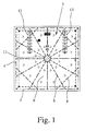
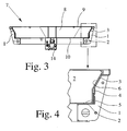
- Fig. 1 - 4th results in a manhole cover with a manhole cover plate for insertion or installation in a arranged at the shaft head of a shaft not shown support 1.
- Das in Fig. 4 illustrated in section support 1 is in concrete at the shaft head of a shaft and therefore fixed. It has horizontally arranged main bearing surfaces 2 for removing the main load of up to 900 kN. In the illustrated and preferred embodiment are adjacent thereto relative to the horizontal inclined arranged auxiliary support surfaces 3. These are normally arranged inclined relative to the horizontal by about 40 ° to about 80 °. In the illustrated embodiment, they are inclined at about 65 °.
- the manhole cover plate itself has, like the Fig. 1 - 4th show an outer peripheral frame 4 with the main bearing surfaces 2 of the support 1 corresponding bottom support surfaces 5 and here with the auxiliary support surfaces 3 of the support 1 corresponding side support surfaces 6.
- frame 4 a supporting structure 7 is attached.
- the manhole cover plate is designed as a self-supporting cassette construction.
- the frame 4 consists of circumferential side plates 4 and the structure 7 of upright, connected to the side plates 4 stiffening plates 8 and an i. w. full-surface upper sheet 9 is.
- the upper plate 9, which forms the continuous surface of the manhole cover plate, is connected to the side plates 4 and / or to the stiffening plates 8.
- Fig. 1 and 2 Let it be seen in conjunction that result in many free spaces by the construction according to the invention, so that regardless of the heavy load capacity of the manhole cover plate according to the invention their weight per unit area is substantially less than in the manhole cover plate of the prior art.
- the illustrated and preferred embodiment shows, in particular in Fig. 2 , further, that the cassette construction is optimized here by the fact that the supporting structure 7 additionally has an iw full-surface lower plate 10 connected to the side plates 4 and / or to the stiffening plates 8.
- the illustrated and preferred embodiment also shows that the sheets are made of steel and are welded together.
- the side plates 4 in the frame 4 crossing each other at right angles preferably i. w. are arranged like a checkerboard.
- stiffening plates 8 in the frame 4 i. w. star-shaped, in this case with a central connecting ring 11, are arranged.
- the star-shaped arrangement of the stiffening plates 8 creates a particularly uniform introduction of the load circumferentially in the support 1 at the shaft head.
- Manhole cover plates of the type in question are available in various cross sections, in particular round or rectangular or square.
- the illustrated embodiment shows a square manhole cover plate measuring 1200 mm x 1200 mm. Due to the cassette construction according to the invention, this manhole cover plate is comparatively easy for its size and for its carrying capacity (according to DIN 124). This is especially true because of the star-shaped arrangement of the stiffening plates 8 in the frame 4.
- the illustrated and preferred embodiment also shows that the star-shaped stiffening plates 8 are connected to the side plates 4 at a distance from the corners of the frame 4. It is important in this construction instruction that the stiffening plates 8 just do not end in the corners, but spaced from the corners. This results in heavy-duty welds at appropriate intervals.
- the illustrated and preferred embodiment shows a total of twelve star-shaped, arranged at equal angular intervals stiffening plates 8, which meet in the middle all on one extending between the upper plate 9 and lower plate 10 terminal ring 11. As a result, each side plate 4 is divided into four sections.
- stiffening plates 8 are arranged near the corners of the frame 4 extending transversely to the bisecting line and connected to the other stiffening plates 8. It is provided that the transverse in the corners stiffening plates 8 are arranged directly under the top plate 9, but do not extend over the full height of the side panels 4.
- Fig. 1 . 2 and 3 can be seen in connection that the manhole cover plate shown here is pivotally mounted on the support 1 of the shaft head.
- the invention provides that in the supporting structure 7, in particular on the lower plate 10, brackets 13 are integrated for pivot hinges and for a damper drive 14.
Landscapes
- Engineering & Computer Science (AREA)
- Environmental & Geological Engineering (AREA)
- Life Sciences & Earth Sciences (AREA)
- General Life Sciences & Earth Sciences (AREA)
- Mining & Mineral Resources (AREA)
- Paleontology (AREA)
- Civil Engineering (AREA)
- General Engineering & Computer Science (AREA)
- Structural Engineering (AREA)
- Underground Structures, Protecting, Testing And Restoring Foundations (AREA)
Applications Claiming Priority (1)
| Application Number | Priority Date | Filing Date | Title |
|---|---|---|---|
| DE202008006008U DE202008006008U1 (de) | 2008-04-30 | 2008-04-30 | Schachtabdeckungsplatte für hohe Lasten |
Publications (2)
| Publication Number | Publication Date |
|---|---|
| EP2113609A2 true EP2113609A2 (fr) | 2009-11-04 |
| EP2113609A3 EP2113609A3 (fr) | 2009-11-18 |
Family
ID=39646532
Family Applications (1)
| Application Number | Title | Priority Date | Filing Date |
|---|---|---|---|
| EP09005404A Withdrawn EP2113609A3 (fr) | 2008-04-30 | 2009-04-16 | Couvercle pour regard chaussée |
Country Status (2)
| Country | Link |
|---|---|
| EP (1) | EP2113609A3 (fr) |
| DE (1) | DE202008006008U1 (fr) |
Families Citing this family (1)
| Publication number | Priority date | Publication date | Assignee | Title |
|---|---|---|---|---|
| DE102011051545A1 (de) | 2011-07-04 | 2013-01-10 | Aco Severin Ahlmann Gmbh & Co. Kg | Schachtabdeckung mit einer Tragstrukturvorrichtung und Verfahren zum Herstellen einer Schachtabdeckung |
Citations (1)
| Publication number | Priority date | Publication date | Assignee | Title |
|---|---|---|---|---|
| DE19703406A1 (de) | 1997-01-30 | 1998-08-06 | Renauer Kanalbau Gmbh H | Rinnen- oder Sinkkastenabdeckung |
Family Cites Families (4)
| Publication number | Priority date | Publication date | Assignee | Title |
|---|---|---|---|---|
| FR2723384B1 (fr) * | 1994-08-08 | 1996-12-20 | Pont A Mousson | Trappe, notamment pour regard technique de bouche d'incendie et ses elements constitutifs |
| DE202005021736U1 (de) * | 2005-01-21 | 2009-09-10 | Aco Severin Ahlmann Gmbh & Co. Kg | Abdeckung für einen Hohlkörper |
| DE202005010323U1 (de) * | 2005-07-01 | 2005-09-15 | Heinrich Meier Eisengieserei G | Schachtabdeckung mit dämpfender Einlage |
| NZ548487A (en) * | 2006-07-12 | 2008-10-31 | Sika Technology Ltd | Access cover |
-
2008
- 2008-04-30 DE DE202008006008U patent/DE202008006008U1/de not_active Expired - Lifetime
-
2009
- 2009-04-16 EP EP09005404A patent/EP2113609A3/fr not_active Withdrawn
Patent Citations (1)
| Publication number | Priority date | Publication date | Assignee | Title |
|---|---|---|---|---|
| DE19703406A1 (de) | 1997-01-30 | 1998-08-06 | Renauer Kanalbau Gmbh H | Rinnen- oder Sinkkastenabdeckung |
Also Published As
| Publication number | Publication date |
|---|---|
| DE202008006008U1 (de) | 2008-07-24 |
| EP2113609A3 (fr) | 2009-11-18 |
Similar Documents
| Publication | Publication Date | Title |
|---|---|---|
| DE602005002760T2 (de) | Windkraftanlageturm, vorgefertigtes metallisches Wandteil zum Gebrauch in diesem Turm, und Verfahren zur Herstellung dieses Turms | |
| EP2798133B1 (fr) | Panneau pour un système de coffrage de plafond et système de coffrage de plafond | |
| EP3320161A1 (fr) | Tour d'une éolienne | |
| DE10002383A1 (de) | Querkraftbeanspruchtes Stahl- oder Spannbetonteil | |
| EP4339398A1 (fr) | Segment de transition d'une tour d'éolienne | |
| EP3436638B1 (fr) | Structure de transition servant au pontage d'un joint de construction | |
| DE3322019C2 (de) | Verfahren zum vorübergehenden Übertragen von außerhalb der Querschnittsfläche eines Bauwerks parallel zu dessen Außenfläche wirkenden Kräften sowie Vorrichtung zum Durchführen des Verfahrens | |
| EP2113609A2 (fr) | Couvercle pour regard chaussée | |
| DE3017196A1 (de) | Gegenueber aggressiven stoffen resistentes kunststoffgehaeuse | |
| EP2428626B1 (fr) | Paroi pour la séparation de produits en vrac | |
| EP0318712A1 (fr) | Dispositif de connexion pour raccorder un plancher en béton à une colonne, et bâtiment | |
| DE102005019034B4 (de) | Verbauvorrichtung | |
| DE3221051C2 (de) | Stahlstruktur mit miteinander verbindbaren Modulen | |
| EP2236704B1 (fr) | Elément de sol, système de sol et système de chapiteau | |
| DE3237467C1 (de) | Traggeruest zum Einruesten von Bauwerken | |
| DE2719490C2 (de) | Dachbinder eines Zelt-Traggerüstes | |
| EP1630315A1 (fr) | Élément de construction pour armature de cisaillement et de poinconnement | |
| EP1669505A1 (fr) | Poutre composite en acier-béton avec support ignifuge pour éléments de plafond | |
| AT18173U1 (de) | Schwimmbecken | |
| DE102005038996A1 (de) | Verbund-Bodenelement | |
| DE102006014809B4 (de) | Bauwerk aus Fertigteilen | |
| DE202017106469U1 (de) | Bedienbühne für Anlagen | |
| EP3427851A1 (fr) | Profilé de construction et combinaison de profilés comprenant au moins deux profilés de construction et un support de main courante | |
| DE102006033050B3 (de) | Gleitschalung | |
| DE2706112C3 (de) | Vorrichtung zum Versetzen einer Raumzelle aus Stahlbeton und mit dieser Vorrichtung versetzbare Raumzelle |
Legal Events
| Date | Code | Title | Description |
|---|---|---|---|
| PUAI | Public reference made under article 153(3) epc to a published international application that has entered the european phase |
Free format text: ORIGINAL CODE: 0009012 |
|
| PUAL | Search report despatched |
Free format text: ORIGINAL CODE: 0009013 |
|
| AK | Designated contracting states |
Kind code of ref document: A2 Designated state(s): AT BE BG CH CY CZ DE DK EE ES FI FR GB GR HR HU IE IS IT LI LT LU LV MC MK MT NL NO PL PT RO SE SI SK TR |
|
| AK | Designated contracting states |
Kind code of ref document: A3 Designated state(s): AT BE BG CH CY CZ DE DK EE ES FI FR GB GR HR HU IE IS IT LI LT LU LV MC MK MT NL NO PL PT RO SE SI SK TR |
|
| STAA | Information on the status of an ep patent application or granted ep patent |
Free format text: STATUS: THE APPLICATION IS DEEMED TO BE WITHDRAWN |
|
| 18D | Application deemed to be withdrawn |
Effective date: 20100519 |