EP2113648A1 - Zylinderkopf für einen verbrennungsmotor - Google Patents
Zylinderkopf für einen verbrennungsmotor Download PDFInfo
- Publication number
- EP2113648A1 EP2113648A1 EP08710944A EP08710944A EP2113648A1 EP 2113648 A1 EP2113648 A1 EP 2113648A1 EP 08710944 A EP08710944 A EP 08710944A EP 08710944 A EP08710944 A EP 08710944A EP 2113648 A1 EP2113648 A1 EP 2113648A1
- Authority
- EP
- European Patent Office
- Prior art keywords
- exhaust
- cylinder head
- path
- combustion engine
- internal
- Prior art date
- Legal status (The legal status is an assumption and is not a legal conclusion. Google has not performed a legal analysis and makes no representation as to the accuracy of the status listed.)
- Granted
Links
Images


Classifications
-
- F—MECHANICAL ENGINEERING; LIGHTING; HEATING; WEAPONS; BLASTING
- F02—COMBUSTION ENGINES; HOT-GAS OR COMBUSTION-PRODUCT ENGINE PLANTS
- F02F—CYLINDERS, PISTONS OR CASINGS, FOR COMBUSTION ENGINES; ARRANGEMENTS OF SEALINGS IN COMBUSTION ENGINES
- F02F1/00—Cylinders; Cylinder heads
- F02F1/24—Cylinder heads
- F02F1/42—Shape or arrangement of intake or exhaust channels in cylinder heads
- F02F1/4264—Shape or arrangement of intake or exhaust channels in cylinder heads of exhaust channels
-
- F—MECHANICAL ENGINEERING; LIGHTING; HEATING; WEAPONS; BLASTING
- F01—MACHINES OR ENGINES IN GENERAL; ENGINE PLANTS IN GENERAL; STEAM ENGINES
- F01N—GAS-FLOW SILENCERS OR EXHAUST APPARATUS FOR MACHINES OR ENGINES IN GENERAL; GAS-FLOW SILENCERS OR EXHAUST APPARATUS FOR INTERNAL-COMBUSTION ENGINES
- F01N13/00—Exhaust or silencing apparatus characterised by constructional features
- F01N13/08—Other arrangements or adaptations of exhaust conduits
- F01N13/10—Other arrangements or adaptations of exhaust conduits of exhaust manifolds
- F01N13/105—Other arrangements or adaptations of exhaust conduits of exhaust manifolds having the form of a chamber directly connected to the cylinder head, e.g. without having tubes connected between cylinder head and chamber
-
- F—MECHANICAL ENGINEERING; LIGHTING; HEATING; WEAPONS; BLASTING
- F01—MACHINES OR ENGINES IN GENERAL; ENGINE PLANTS IN GENERAL; STEAM ENGINES
- F01N—GAS-FLOW SILENCERS OR EXHAUST APPARATUS FOR MACHINES OR ENGINES IN GENERAL; GAS-FLOW SILENCERS OR EXHAUST APPARATUS FOR INTERNAL-COMBUSTION ENGINES
- F01N3/00—Exhaust or silencing apparatus having means for purifying, rendering innocuous, or otherwise treating exhaust
- F01N3/08—Exhaust or silencing apparatus having means for purifying, rendering innocuous, or otherwise treating exhaust for rendering innocuous
- F01N3/10—Exhaust or silencing apparatus having means for purifying, rendering innocuous, or otherwise treating exhaust for rendering innocuous by thermal or catalytic conversion of noxious components of exhaust
- F01N3/18—Exhaust or silencing apparatus having means for purifying, rendering innocuous, or otherwise treating exhaust for rendering innocuous by thermal or catalytic conversion of noxious components of exhaust characterised by methods of operation; Control
- F01N3/20—Exhaust or silencing apparatus having means for purifying, rendering innocuous, or otherwise treating exhaust for rendering innocuous by thermal or catalytic conversion of noxious components of exhaust characterised by methods of operation; Control specially adapted for catalytic conversion
- F01N3/2006—Periodically heating or cooling catalytic reactors, e.g. at cold starting or overheating
-
- F—MECHANICAL ENGINEERING; LIGHTING; HEATING; WEAPONS; BLASTING
- F02—COMBUSTION ENGINES; HOT-GAS OR COMBUSTION-PRODUCT ENGINE PLANTS
- F02B—INTERNAL-COMBUSTION PISTON ENGINES; COMBUSTION ENGINES IN GENERAL
- F02B37/00—Engines characterised by provision of pumps driven at least for part of the time by exhaust
- F02B37/02—Gas passages between engine outlet and pump drive, e.g. reservoirs
- F02B37/025—Multiple scrolls or multiple gas passages guiding the gas to the pump drive
-
- F—MECHANICAL ENGINEERING; LIGHTING; HEATING; WEAPONS; BLASTING
- F02—COMBUSTION ENGINES; HOT-GAS OR COMBUSTION-PRODUCT ENGINE PLANTS
- F02B—INTERNAL-COMBUSTION PISTON ENGINES; COMBUSTION ENGINES IN GENERAL
- F02B37/00—Engines characterised by provision of pumps driven at least for part of the time by exhaust
- F02B37/12—Control of the pumps
- F02B37/18—Control of the pumps by bypassing exhaust from the inlet to the outlet of turbine or to the atmosphere
-
- F—MECHANICAL ENGINEERING; LIGHTING; HEATING; WEAPONS; BLASTING
- F02—COMBUSTION ENGINES; HOT-GAS OR COMBUSTION-PRODUCT ENGINE PLANTS
- F02F—CYLINDERS, PISTONS OR CASINGS, FOR COMBUSTION ENGINES; ARRANGEMENTS OF SEALINGS IN COMBUSTION ENGINES
- F02F1/00—Cylinders; Cylinder heads
- F02F1/24—Cylinder heads
- F02F1/243—Cylinder heads and inlet or exhaust manifolds integrally cast together
-
- Y—GENERAL TAGGING OF NEW TECHNOLOGICAL DEVELOPMENTS; GENERAL TAGGING OF CROSS-SECTIONAL TECHNOLOGIES SPANNING OVER SEVERAL SECTIONS OF THE IPC; TECHNICAL SUBJECTS COVERED BY FORMER USPC CROSS-REFERENCE ART COLLECTIONS [XRACs] AND DIGESTS
- Y02—TECHNOLOGIES OR APPLICATIONS FOR MITIGATION OR ADAPTATION AGAINST CLIMATE CHANGE
- Y02T—CLIMATE CHANGE MITIGATION TECHNOLOGIES RELATED TO TRANSPORTATION
- Y02T10/00—Road transport of goods or passengers
- Y02T10/10—Internal combustion engine [ICE] based vehicles
- Y02T10/12—Improving ICE efficiencies
Definitions
- the present invention relates to a cylinder head of an internal-combustion engine including a combustion chamber configured by being fastened to an upper portion of a cylinder block, in which an intake path and an exhaust path are provided to the combustion chamber.
- the cylinder head is assembled to the upper portion of the cylinder block and is fastened by a plurality of fastening bolts, and a plurality of combustion chambers are arranged in a linear fashion.
- An intake port and an exhaust port are formed for each of the combustion chambers, respectively, so as to oppose to each other, in which an intake path communicates with each intake port, on the other hand, an exhaust path communicates with each exhaust port, and they may be opened and closed by an intake valve and an exhaust valve, respectively.
- an injector for injecting fuel into each intake path or each combustion chamber is mounted, and an ignition plug for igniting mixed air in the combustion chamber is mounted.
- An intake tube is connected to each intake path through an intake manifold, on the other hand, an exhaust tube is connected to each exhaust path through an exhaust manifold.
- an internal-combustion engine there is one, which is made smaller by integrally providing an exhaust assembling section in the cylinder head, without fixing a separate exhaust manifold to the cylinder head.
- the conventional cylinder head with the exhaust assembling section integrally formed is configured such that the exhaust ports communicate with a plurality of combustion chambers, the exhaust ports are assembled to open on a side surface, the exhaust tube is connected to the assembling section, and a turbo supercharger is mounted on the exhaust tube.
- Patent Document 1 JP-A-01-182560
- An exhaust purification catalyst is mounted together with the turbo supercharger on an exhaust system of the internal-combustion engine. At the time of a cold start of the internal-combustion engine, by delaying ignition timing to introduce high-temperature exhaust gas to the purification catalyst through the exhaust pipe, the exhaust purification catalyst is warmed up for quick activation.
- the warm-up of the exhaust purification catalyst can be promoted by reducing a cross-sectional area of the exhaust path to inhibit lowering of an exhaust gas temperature.
- the exhaust gas passes through the turbine of the turbo supercharger even at the time of the cold start, so that the heat of the exhaust gas is herein taken away and there is a problem that the catalyst warm-up performance is lowered.
- the present invention is to solve such a problem, and an object thereof is to provide the cylinder head of the internal-combustion engine in which the catalyst warm-up performance is improved and the device is made compact-sized.
- a cylinder head of an internal-combustion engine includes a plurality of combustion chambers; a plurality of intake paths communicating with each of the combustion chambers through intake ports, respectively; and an exhaust path having one ends communicating with each of the combustion chambers through exhaust ports, respectively, and an assembling section at which the other ends are assembled, wherein a supercharger and an exhaust purification catalyst are connected to the assembling section of the exhaust path, a bypass path communicating from the exhaust path to the exhaust purification catalyst by bypassing the supercharger is provided, and a control valve capable of opening and closing the bypass path is provided, and wherein a part of the bypass path is provided in the cylinder head of the internal-combustion engine.
- a bypass hole having one end communicating with the assembling section of the exhaust path and the other end opening on a side surface of the cylinder head is formed as the bypass path.
- the other end of the bypass hole is formed so as to open on a side portion on which the assembling section of the exhaust path opens.
- control valve is provided so as to be capable of opening and closing the other end of the bypass hole.
- the control valve is composed of a valve body capable of opening and closing the other end of the bypass hole, an actuator, and a link connecting the actuator and the valve body, as a unit, and the control valve unit is provided on the side surface of the cylinder head.
- a turbine housing of the supercharger has a scroll section, and the scroll section communicates with the assembling section of the exhaust path by being fixed to the side surface of the cylinder head.
- a turbine housing of the supercharger has an exhaust guiding section having one end opening to outside and a scroll section with which the other end of the exhaust guiding section communicates, and the exhaust guiding section is arranged in the assembling section of the exhaust path.
- a cooling path is provided on the turbine housing of the supercharger, and the cooling path communicates with a water jacket provided in the cylinder head.
- the cooling path is provided on an outer peripheral portion of the turbine housing, a cooling water inlet communicating with the water jacket is formed on an upper end of the turbine housing, and a cooling water outlet communicating with the water jacket is formed on a lower end of the turbine housing.
- one ends of the exhaust path communicate with a plurality of combustion chambers through the exhaust ports, respectively, the assembling section is provided on the other ends thereof, the supercharger and the exhaust purification catalyst are connected to the assembling section, the bypass path communicating from the exhaust path to the exhaust purification catalyst by bypassing the supercharger is provided, and the control valve capable of opening and closing the bypass path is provided, then a part of the bypass path is provided in the cylinder head, so that it is possible to inhibit the lowering of the exhaust gas temperature to improve the catalyst warm-up performance by reducing a path surface area from the combustion chamber to the exhaust purification catalyst, and there is an effect of making a device compact by simplifying tube arrangement for discharging the exhaust gas.
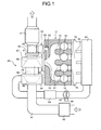
- Fig. 1 is a schematic diagram illustrating a cylinder head of an internal-combustion engine according to a first embodiment of the present invention
- Fig. 2 is a vertical cross-sectional view illustrating the internal-combustion engine of the first embodiment
- Fig. 3 is a vertical cross-sectional view illustrating the cylinder head of the internal-combustion engine of the first embodiment
- Fig. 4 is a cross-sectional view illustrating a waste gate valve in the internal-combustion engine of the first embodiment.
- the internal-combustion engine of the first embodiment is an in-line four-cylinder engine, and as shown in Figs. 1 and 2 , a cylinder block 12 is assembled to a lower portion of a cylinder head 11 and fastened by a plurality of fastening bolts not shown.
- a plurality of (four, in the present embodiment) cylinder bores 13 are formed on the cylinder block 12 so as to be arranged in a linear fashion, and a piston 14 fits each cylinder bore 13 so as to be movable in an axial direction thereof.
- a crankshaft not shown is rotatably supported on a lower portion of the cylinder block 12, and each piston 14 is connected to the crankshaft through a connecting rod 15.
- the cylinder head 11 has combustion chambers 16 formed thereon, one above each cylinder bore 13, respectively, so as to correspond thereto.
- the combustion chamber 16 is enclosed by an inner wall surface of the cylinder bore 13, a lower surface of the cylinder head 11 and a top surface of the piston 14, and is formed into a pent-roof shape in which a ceiling portion (the lower surface of the cylinder head 11) is inclined such that a central portion thereof is high.
- An intake port 17 and an exhaust port 18 are opened above each combustion chamber 16, that is to say, on the lower surface of the cylinder head 11, so as to be opposed to each other.
- each intake path 19 each having one end communicating with each intake port 17 and the other end opening on one side surface thereof are formed.
- one exhaust path 20 having one ends each communicating with each exhaust port 18, and other ends assembled and opening to the other side surface thereof is formed.
- the exhaust path 20 has four exhaust path sections 21 each communicating with each exhaust port 18 and an assembling section 22 at which the ends of the exhaust path sections 21 are assembled, in which each exhaust path section 21 communicates with the combustion chamber 16 through the exhaust port 18, and the assembling section 22 opens on the other side surface of the cylinder head 11.
- An intake valve 23 and an exhaust valve 24 are positioned so as to correspond to each intake port 17 and each exhaust port 18, respectively.
- the intake valve 23 and the exhaust valve 24 are supported by stem guides 25 and 26 fixed to the cylinder head 11, respectively, so as to be movable in an axial direction, and are biasingly supported by valve springs 27 and 28, respectively, in a direction to close the intake port 17 and the exhaust port 18.
- one ends of roller rocker arms 29 and 30 are connected to upper ends of the intake valve 23 and the exhaust valve 24, respectively, and the other ends of the roller rocker arms 29 and 30 are connected to lash adjusters 31 and 32 fixed to the cylinder head 11, respectively, and an intake cam 34 of an intake cam shaft 33 and an exhaust cam 36 of an exhaust cam shaft 35 contact the roller rocker arms 29 and 30, respectively.
- the intake cam 34 and the exhaust cam 36 activate the roller rocker arms 29 and 30, respectively, and the intake valve 23 and the exhaust valve 24 move up and down at predetermined timing to open and close the intake port 17 and the exhaust port 18, respectively, thereby allowing the intake path 19 and the combustion chamber 16, and the combustion chamber 16 and the exhaust path section 21 of the exhaust path 20 to communicate with each other.
- an injector 37 for directly injecting fuel into the combustion chamber 16 is mounted on a side portion of the combustion chamber 16, that is to say, on the lower surface of the cylinder head 11 on an intake path 19 side.
- an ignition plug 38 is mounted on the central portion of the ceiling portion of the combustion chamber 16, that is to say, on the lower surface of the cylinder head 11 between the intake path 19 and the exhaust path section 21.
- An electronic control unit (ECU) is mounted on a vehicle, and the ECU can control fuel injection timing of the injector 37 and ignition timing by the ignition plug 38 and determines a fuel injection amount, the injection timing, the ignition timing or the like based on an engine operating state such as detected intake air quantity, throttle opening (accelerator opening) and an engine rotational number.
- An intake manifold 39 communicating with each intake path 19 is fixed to one side surface of the cylinder head 11, and a surge tank 40 is connected to the intake manifold 39.
- An intake tube 41 has an air cleaner 42 attached to an air inlet on an upstream side thereof and a downstream side end connected to the surge tank 40, and is provided with an electronic throttle device 44 having a throttle valve 43 located on a downstream side of the air cleaner 42.
- a turbo supercharger 45 communicating with the assembling section 22 of the exhaust path 20 is fixed to the other side surface of the cylinder head 11, an exhaust tube 46 is connected to the turbo supercharger 45, and an exhaust purification catalyst (three-way catalyst) 47 is mounted on the exhaust tube 46.
- the turbo supercharger 45 is composed of a compressor 48 provided on an intake tube 41 side and a turbine 49 provided on an exhaust tube 46 side integrally connected to each other by a connecting shaft 50.
- An intercooler 51 for cooling intake air of which temperature is increased by compression by the compressor 48 is provided on the intake tube 41 on a downstream side of the compressor 48 in the turbo supercharger 45 and on an upstream side of the electronic throttle device 44 (throttle valve 43).
- a bypass path 52 communicating from the exhaust path 20 formed on the cylinder head 11 to the exhaust purification catalyst 47 by bypassing the turbo supercharger 45 is provided and an exhaust control valve 53 having a wastegate function capable of opening and closing the bypass path 52 is provided, and a part of the bypass path 52 is provided in the cylinder head 11.
- the intake path 19 having the one end communicating with the combustion chamber 16 is formed on the cylinder head 11, and the other end of the intake path 19 opens on one side surface of the cylinder head 11.
- the exhaust path 20 having the one ends communicating with the combustion chambers 16 is formed on the cylinder head 11, and the other ends of the exhaust path 20 open on the other side surface of the cylinder head 11 as the assembling section 22.
- water jackets 54a and 54b are formed so as to be located above and below the intake path 19, on the other hand, water jackets 55a and 55b are formed so as to be located above and below the exhaust path 20.
- Each of the water jackets 54a, 54b, 55a and 55b is filled with engine cooling water, which can be circulated by a water pump not shown.
- the turbo supercharger 45 is composed of the compressor 48 and the turbine 49 integrally connected to each other by the connecting shaft 50, in which the compressor 48 is accommodated in a compressor housing 56, the turbine 49 is accommodated in a turbine housing 57 and the connecting shaft 50 is accommodated in a connecting shaft housing 58, and the housings 56, 57 and 58 are integrally connected to one another.
- the turbine housing 57 is composed of an inner housing 57a having a scroll section 59 formed therein and an outer housing 57b covering the inner housing 57a and having a cooling path 60 formed therein.
- the inner housing 57a is produced by casting
- the outer housing 57b is produced by sheet metal processing
- the housings 57a and 57b are integrally adhered to each other.
- an exhaust introducing section 59a of the scroll section 59 adheres closely to the side surface of the cylinder head 11 so as to communicate with the assembling section 22 of the exhaust path 20, and a flange section 57c is fixed to the cylinder head 11 by a plurality of fastening bolts 61.
- a cooling water inlet 60a is formed on an upper end thereof and a cooling water outlet 60b is formed on a lower end thereof, and in a state in which this is fixed to the cylinder head 11, the cooling water inlet 60a communicates with the water jacket 55a and the cooling water outlet 60b communicates with the water jacket 55b.
- the above-described bypass path 52 is composed of a bypass hole 62 formed in the cylinder head 11 and a bypass tube 63 connecting the cylinder head 11 and the exhaust tube 46, and the exhaust control valve 53 is connected to the bypass tube 63.
- the bypass hole 62 is integrally formed in the cylinder head 11 and in an L-shape in plane view, in which one end thereof communicates with a side portion of the assembling section 22 in the exhaust path 20 and the other end thereof opens on the side surface of the cylinder head 11.
- the other end of the bypass hole 62 opens on a side on which the assembling section 22 of the exhaust path 20 opens. That is to say, on the side surface of the cylinder head 11, the opening of the bypass hole 62 and the opening of the assembling section 22 in the exhaust path 20 are formed so as to be aligned in a horizontal direction.
- a case 64 has a cylindrical box shape, in which one end thereof adheres closely to the side surface of the cylinder head 11 and the other end thereof adheres closely to one end of the bypass tube 63, and they are fixed by fastening bolts not shown.
- a base end of an arm 65 is rotatably supported on the case 64 by means of a support shaft 66, and a valve body 67 capable of opening and closing the other end (opening) of the bypass hole 62 is attached thereto.
- the valve body 67 can adhere closely to a valve sheet (seal member) 68 mounted on the side surface of the cylinder head 11 in the vicinity of the opening of the bypass hole 62 so as to close the opening of the bypass hole 62.
- an actuator 69 is mounted on the cylinder head 11, and a tip end of a drive rod 69a and the base end of the arm 65 are connected to each other by means of a link 70. Meanwhile, the other end of the bypass tube 63 is connected between the turbo supercharger 45 and the exhaust purification catalyst 47 in the exhaust tube 46.
- the exhaust control valve 53 is composed of the case 64, the arm 65, the support shaft 66, the valve body 67, the actuator 69 and the link 70, as a unit, and this exhaust control valve unit is provided on the side surface of the cylinder head 11. Therefore, by driving the actuator 69 to move the drive rod 69a in an axial direction, it is possible to rotate the arm 65 about the support shaft 66 through the link 70, and to open and close the bypass hole 62, that is to say, the bypass path 52, by the valve body 67.
- the exhaust valve 53 can control a supercharging pressure by the turbo supercharger 45 by opening and closing the bypass path 52, and when the supercharging pressure on an intake side reaches a predetermined pressure, this discharges the exhaust gas to inhibit rotation of the turbine 49 so as to prevent further pressurization by the compressor 48. Also, as described later, the exhaust control valve 53 intend to obtain quick activation by warming up the exhaust purification catalyst 47, by allowing the exhaust gas to directly flow into the exhaust purification catalyst 47 by bypassing the turbine 49, at the time of a cold start of the engine.
- the exhaust gas in each combustion chamber 16 flows through the exhaust port 18 to the exhaust path 20, assembled at the assembling section 22 to be discharged from the cylinder head 11.
- the exhaust gas discharged from the cylinder head 11 drives the turbine 49 of the turbo supercharger 45, and by driving the compressor 48 connected to the turbine 49 by the connecting shaft 50, the air introduced into the intake tube 41 can be compressed.
- the exhaust gas, which has driven the turbine 49 flows through the exhaust tube 46 into the exhaust purification catalyst 47, and harmful substances in the exhaust gas are herein purified and discharged to atmosphere.
- the exhaust purification catalyst 47 At the time of the cold start of the engine, the exhaust purification catalyst 47 is in a low-temperature state and the temperature does not reach an activation temperature of the exhaust gas, so that it is configured such that consumption of combustion energy of the fuel for driving the engine is reduced by largely delaying the ignition timing and igniting by the ignition plug 38, and the exhaust purification catalyst 47 is rapidly warmed up by the high-temperature exhaust gas. Therefore, at that time, the ECU drives the actuator 69 of the exhaust control valve 53 to open the bypass hole 62 (bypass path 52) by the valve body 67.
- the high-temperature exhaust gas discharged from the combustion chamber 16 through the exhaust port 18 to the exhaust path 20 flows from the assembling section 22 through the bypass path 52 to the exhaust tube 46, and directly flows into the exhaust purification catalyst 47 by bypassing the turbo supercharger 45. Therefore, it is possible to efficiently warm up the exhaust purification catalyst 47 by the high-pressure exhaust gas to activate the same.
- the engine cooling water flowing through the water jacket 55a of the cylinder head 11 is introduced from the cooling water inlet 60a of the turbine housing 57 to the cooling path 60, flows outside the scroll section 59, and discharged from the cooling water outlet 60b to the water jacket 55b. Therefore, the turbine 49 and the turbine housing 57 heated by the high-temperature exhaust gas are appropriately cooled.
- the one ends of the exhaust path 20 communicate with a plurality of combustion chambers 16 through the exhaust ports 18, respectively, the assembling section 22 is provided on the other ends of the exhaust path 20, and the turbo supercharger 45, the exhaust tube 46 and the exhaust purification catalyst 47 are connected to the assembling section 22, on the other hand, the bypass path 52 for communicating from the exhaust path 20 to the exhaust tube 46 and the exhaust purification catalyst 47 by bypassing the turbo supercharger 45 is provided and the exhaust control valve 53, which may open and close the bypass path 52, is provided, and a part of the bypass path 52 is provided in the cylinder head 11.
- the high-temperature exhaust gas 26 discharged from the combustion chamber 16 through the exhaust port 18 to the exhaust path 20 flows from the assembling section 22 through the bypass path 52 to the exhaust tube 46, and directly flows into the exhaust purification catalyst 47 by bypassing the turbo supercharger 45. Therefore, a path surface area from the combustion chamber 16 to the exhaust purification catalyst 47 is reduced, heat of the high-temperature exhaust gas is not taken away by the turbo supercharger 45 and lowering of the exhaust gas temperature is inhibited, so that it is possible to efficiently warm up the exhaust purification catalyst 47 by the exhaust gas to activate the same, and the catalyst warm-up performance can be improved.
- bypass hole 62 as a part of the bypass path 52 is formed in the cylinder head 11. Therefore, by forming the bypass hole 62 in the cylinder head 11 in a high-temperature state, it is possible to inhibit the lowering of the exhaust gas temperature, thereby improving catalyst warm-up performance, and by simplifying tube arrangement (bypass tube 63) exposed outside, the device can be made compact.
- the bypass hole 62 is formed in the cylinder head 11 as the bypass path 52, in which the one end of the bypass hole 62 communicates with the assembling section 22 of the exhaust path 20, and the other end thereof opens on the side surface of the cylinder head 11. Therefore, it is possible to shorten distance from the exhaust path 20 to the exhaust purification catalyst 47 to inhibit the lowering of the exhaust gas temperature, thereby improving the catalyst warm-up performance, and since the exhaust gas is taken out of the assembling section 22, variation in a back pressure among each cylinder disappears and the combustion can be improved.
- the bypass hole 62 is formed such that the other end thereof opens on the side portion on which the assembling section 22 of the exhaust path 20 opens, and the turbine housing 57 of the turbo supercharger 45, the exhaust tube 46 and the exhaust purification catalyst 47 can be easily mounted thereon, so that the device can be made simple.
- the exhaust control valve 53 is provided so as to be able to open and close a seaport of the other end of the bypass hole 62.
- the exhaust control valve 53 is composed of the case 64, the arm 65, the support shaft 66, the valve body 67, the actuator 69 and the link 70, as the unit, and the exhaust control valve unit is provided on the side surface of the cylinder head 11. Therefore, by providing the exhaust control valve 53 on the cylinder head 11 side, which is maintained in a low-temperature state than the exhaust tube 46, damage by heat can be prevented to improve reliability, and a heat resistant material can be reduced to realize a low cost.
- the scroll section 59 is provided on the turbine housing 57 of the turbo supercharger 45, and by fixing the turbine housing 57 to the side surface of the cylinder head 11, the scroll section 59 communicates with the assembling section 22 of the exhaust path 20. Therefore, the structure of the turbo supercharger 45 can be made compact and simple and low cost device can be obtained.
- the cooling path 60 is provided on the turbine housing 57 of the turbo supercharger 45, and the cooling path 60 communicates with the water jackets 55a and 55b provided in the cylinder head 11. Therefore, the engine cooling water flowing through the water jacket 55a of the cylinder head 11 can be introduced into the cooling path 60 of the turbine housing 57 for cooling, and the turbine 49 and the turbine housing 57 heated by the high-temperature exhaust gas are appropriately cooled, so that lowering cost of material can be realized.
- the cooling path 60 is provided on an outer peripheral portion of the turbine housing 57, in which the cooling water inlet 60a communicating with the water jacket 55a is formed on the upper end thereof and the cooling water outlet 60b communicating with the water jacket 55b is formed on the lower end thereof. Therefore, the engine cooling water flowing through the water jacket 55a of the cylinder head 11 is introduced from the cooling water inlet 60a of the turbine housing 57 to the cooling path 60, flows outside the scroll section 59, and is discharged from the cooling water outlet 60b to the water jacket 55b, so that the turbine 49 and the turbine housing 57 heated by the high-temperature exhaust gas can be efficiently cooled.
- the turbine housing 57 is composed of the inner housing 57a forming the scroll section 59 and the outer housing 57b covering the inner housing 57a and forming the cooling path 60, and the inner housing 57a is produced by casting and the outer housing 57b is produced by the sheet metal processing, and the housings 57a and 57b are integrally adhered to each other. Therefore, heat resistance and strength can be ensured by the inner housing 57a, and weight saving and low cost can be realized by the outer housing 57b.
- Fig. 5 is a schematic diagram illustrating the cylinder head of the internal-combustion engine according to a second embodiment of the present invention
- Fig. 6 is a vertical cross-sectional view illustrating the cylinder head of the internal-combustion engine of the second embodiment.
- the same reference numeral is given to the member having the function similar to that of the member described in the above-described embodiment, and the description thereof is not repeated.
- the cylinder block 12 is assembled to a lower portion of a cylinder head 71 and is fastened by a plurality of fastening bolts not shown.
- a plurality of combustion chambers 16 are formed, in which the intake port 17 and the exhaust port 18 open so as to oppose to each other, the intake path 19 communicates through the intake port 17 and the exhaust path 20 communicates through the exhaust port 18, and the exhaust path 20 has the four exhaust path sections 21 and one assembling section 22, in which the assembling section 22 opens on the other side surface of the cylinder head 71.
- the turbo supercharger 45 communicating with the assembling section 22 of the exhaust path 20 is fixed to the side surface of the cylinder head 71, the exhaust tube 46 is connected to the turbo supercharger 45, and the exhaust purification catalyst 47 is mounted on the exhaust tube 46.
- a bypass path 72 communicating from the exhaust path 20 formed on the cylinder head 71 to the exhaust purification catalyst 47 by bypassing the turbo supercharger 45 is provided and an exhaust control valve 73 having the wastegate function capable of opening and closing the bypass path 72 is provided, and a part of the bypass path 72 is provided in the cylinder head 71.
- the bypass path 72 is composed of a bypass hole 74 formed in the cylinder head 11 and a bypass tube 75 connecting the cylinder head 71 and the exhaust tube 46, and the exhaust control valve 73 is connected on a cylinder head 71 side. That is to say, the bypass hole 74 is integrally formed in the cylinder head 71 so as to incline, in which an upper end thereof communicates with a lower portion of the assembling section 22 in the exhaust path 20, and a lower end thereof opens on the side surface of the cylinder head 71. In this case, the lower end of the bypass hole 74 opens below a lower portion on which the assembling section 22 of the exhaust path 20 opens. That is to say, on the side surface of the cylinder head 71, the opening of the bypass hole 74 and the opening of the assembling section 22 in the exhaust path 20 are formed so as to be aligned in a vertical direction.
- the exhaust control valve 73 is mounted on the opening of the bypass hole 74 of the cylinder head 71, and the bypass tube 75 is connected thereto. Meanwhile, although not shown, the other end of the bypass tube 75 is connected between the turbo supercharger 45 and the exhaust purification catalyst 47 in the exhaust tube 46.
- the operation of the engine according to the present embodiment is substantially similar to that of the above-described first embodiment, so that the description thereof is omitted.
- one ends of the exhaust path 20 communicate with a plurality of combustion chambers 16 through the exhaust ports 18, respectively, the assembling section 22 is provided on the other ends of the exhaust path 20, and the turbo supercharger 45, the exhaust tube 46 and the exhaust purification catalyst 47 are connected to the assembling section 22, on the other hand, the bypass path 72 communicating from the exhaust path 20 to the exhaust tube 46 and the exhaust purification catalyst 47 by bypassing the turbo supercharger 45 is provided, and the exhaust control valve 73 capable of opening and closing the bypass path 72 is provided, and the bypass hole 74 as a part of the bypass path 72 is formed in the cylinder head 71.
- the high-temperature exhaust gas discharged from the combustion chamber 16 through the exhaust port 18 to the exhaust path 20 flows from the assembling section 22 through the bypass path 72 to the exhaust tube 46, and directly flows into the exhaust purification catalyst 47 by bypassing the turbo supercharger 45. Therefore, the path surface area from the combustion chamber 16 to the exhaust purification catalyst 47 is reduced, the heat of the high-temperature exhaust gas is not taken away by the turbo supercharger 45 and the lowering of the exhaust gas temperature is inhibited, so that it is possible to efficiently warm up the exhaust purification catalyst 47 by the exhaust gas to activate the same, and the catalyst warm-up performance can be improved.
- bypass hole 74 as a part of the bypass path 72 is formed in the cylinder head 71. Therefore, by forming the bypass hole 74 in the cylinder head 11 in the high-temperature state, it is possible to inhibit the lowering of the exhaust gas temperature to improve the catalyst warm-up performance, and by simplifying the tube arrangement (bypass tube 75) exposed to the outside, the device can be made compact.
- the bypass hole 74 is formed in the cylinder head 71, and the one end of the bypass hole 74 communicates with the assembling section 22 of the exhaust path 20 and the other end thereof opens on the side surface of the cylinder head 11. Therefore, it is possible to shorten the distance from the exhaust path 20 to the exhaust purification catalyst 47 to inhibit the lowering of the exhaust gas temperature, thereby improving the catalyst warm-up performance, and since the exhaust gas is taken out of the assembling section 22, the variation in the back pressure among each cylinder disappears and the combustion can be improved.
- Fig. 7 is a schematic diagram illustrating the cylinder head of the internal-combustion engine according to a third embodiment of the present invention
- Fig. 8 is a substantial part vertical cross-sectional view (cross-sectional view taken along line VIII-VIII of Fig. 7 ) illustrating the cylinder head of the internal-combustion engine of the third embodiment.
- the same reference numeral is given to the member having the function similar to that of the member described in the above-described embodiment, and the description thereof is not repeated.
- a plurality of combustion chambers 82a, 82b, 82c and 82d are formed on a cylinder head 81, in which intake ports 83a, 83b, 83c and 83d and exhaust ports 84a, 84b, 84c and 84d open so as to oppose to each other, respectively, four intake paths 85a, 85b, 85c and 85d communicate through the intake ports 83a, 83b, 83c and 83d and one exhaust path 86 communicates through the exhaust ports 84a, 84b, 84c and 84d, and the exhaust path 86 has four exhaust path sections 87a, 87b, 87c and 87d and two assembling sections 88a and 88b, and the assembling sections 88a and 88b communicate with a connecting hole 89 opening on the other side surface of the cylinder head 81.
- An intake manifold 90 communicating with each of the intake paths 85a, 85b, 85c and 85d is fixed to one side surface of the cylinder head 81, and a surge tank 91 is connected to the intake manifold 90.
- An intake tube 92 has an air cleaner 93 attached to an air inlet on an upstream side thereof, and a downstream side end connected to the surge tank 91, and is provided with an electronic throttle device 95 having a throttle valve 94 located on a downstream side of the air cleaner 93.
- a turbo supercharger 96 communicating with the assembling sections 88a and 88b of the exhaust path 86 is fixed to the connecting hole 89 on the other side surface of the cylinder head 81, the exhaust tube 97 is connected to the turbo supercharger 96, and the exhaust purification catalyst 98 is mounted on the exhaust tube 97.
- a bypass path communicating from the exhaust path 86 formed on the cylinder head 81 to the exhaust purification catalyst 98 by bypassing the turbo supercharger 96, and an exhaust control valve are provided.
- the turbo supercharger 96 is a twin-entry type turbo supercharger, and is formed of a compressor 101 and a turbine 102 integrally connected by a connecting shaft 103, in which the compressor 101 is accommodated in a compressor housing 104, the turbine 102 is accommodated in a turbine housing 105, and the connecting shaft 103 is accommodated in a connecting shaft housing 106, and the housings 104, 105 and 106 are integrally connected to one another.
- the turbine housing 105 has two scroll sections not shown formed therein.
- a connecting section 107 which can fit the connecting hole 89 of the cylinder head 81, is connected to the turbine housing 105 of the turbo supercharger 96.
- the connecting section 107 is composed of an inner cylinder 108 and an outer cylinder 109, and two exhaust guiding sections 110 and 111 are formed.
- the exhaust guiding sections 110 and 111 are configured such that one ends thereof communicate with each scroll section in the turbine housing 105, on the other hand, an opening 110a is formed on the other end of the exhaust guiding section 110 and the other end of the exhaust guiding section 111 changes speed and openings 111a are formed on right and left sides thereof.
- an internal thread 89a is formed on an entry of the connecting hole 89 of the cylinder head 81
- an external thread 107a which can be threadably mounted on the internal thread 89a, is formed on a base end side of the connecting section 107
- a rock nut 112 is threadably mounted on the external thread 107a.
- the turbine housing 105 is fixed to the cylinder head 81. Then, in such a state, the exhaust guiding sections 110 and 111 of the turbine housing 105 are arranged in the assembling sections 88a and 88b in an exhaust path 86 of the cylinder head 71.
- combustion chambers 82b and 82c communicate with the exhaust guiding section 110 through the exhaust path sections 87b and 87c and the assembling section 88a, and the combustion chambers 82a and 82d communicate with the exhaust guiding section 111 through the exhaust path sections 87a and 87d and the assembling section 88b.
- the exhaust gas in each of the combustion chambers 82b and 82c is introduced into the exhaust guiding section 110 through the exhaust path sections 87b and 87c and the assembling section 88a, and flows through the exhaust guiding section 110 into one scroll section in the turbo supercharger 96
- the exhaust gas in each of the combustion chambers 82a and 82d is introduced into the exhaust guiding section 111 through the exhaust path sections 87a and 87d and the assembling section 88b, and flows through the exhaust guiding section 111 into the other scroll section in the turbo supercharger 96. Therefore, by driving the turbine 102 by the exhaust gas flowing into each scroll sections to drive the compressor 101 connected to the turbine 102 by the connecting shaft 103, the air introduced into the intake tube 92 can be compressed. Then, the exhaust gas, which has driven the turbine 102, flows into the exhaust purification catalyst 98 through the exhaust tube 97, and herein, the harmful substances in the exhaust gas are purified and are discharged to atmosphere.
- one ends of the exhaust path 86 communicate with a plurality of combustion chambers 82a, 82b, 82c and 82d through the exhaust ports 84a, 84b, 84c and 84d, respectively, the assembling sections 88a and 88b are provided on the other ends of the exhaust path 86, the turbo supercharger 96, the exhaust tube 97 and the exhaust purification catalyst 98 are connected to the assembling sections 88a and 88b, the exhaust guiding sections 110 and 111 having one ends opening to the outside are provided on the connecting section 107 of the turbine housing 105, and the exhaust guiding sections 110 and 111 are arranged in the assembling sections 88a and 88b of the exhaust path 86.
- the exhaust guiding sections 110 and 111 are arranged in the cylinder head 81, it is possible to reduce the size of the turbo supercharger 96 itself, and the path surface area from the combustion chambers 82a, 82b, 82c and 82d to the exhaust purification catalyst 98 is reduced, the heat of the high-temperature exhaust gas is not taken away by the turbo supercharger 96 and the lowering of the exhaust gas temperature is inhibited, so that it is possible to efficiently warm up the exhaust purification catalyst 98 by the exhaust gas to activate the same, thereby improving the catalyst warm-up performance.
- the internal-combustion engine is described as the in-line four-cylinder engine in the above-described embodiments, the engine is not limited to this type. Also, although the internal-combustion engine is described as an in-cylinder injection type in which the fuel is directly injected into the combustion chamber in the above-described embodiment, the effect similar to that described above can be obtained by applying the invention to a port-injection type internal-combustion engine in which the fuel is injected into the intake port.
- the cylinder head of the internal-combustion engine according to the present invention is to improve the catalyst warm-up performance and realize the compact device by providing a part of the bypass path for bypassing the supercharger therein, and is preferably used in every type of the internal-combustion engine.
Landscapes
- Engineering & Computer Science (AREA)
- Chemical & Material Sciences (AREA)
- Combustion & Propulsion (AREA)
- Mechanical Engineering (AREA)
- General Engineering & Computer Science (AREA)
- Chemical Kinetics & Catalysis (AREA)
- Health & Medical Sciences (AREA)
- Toxicology (AREA)
- Supercharger (AREA)
- Cylinder Crankcases Of Internal Combustion Engines (AREA)
- Exhaust Gas After Treatment (AREA)
Applications Claiming Priority (2)
| Application Number | Priority Date | Filing Date | Title |
|---|---|---|---|
| JP2007028236A JP4803059B2 (ja) | 2007-02-07 | 2007-02-07 | 内燃機関のシリンダヘッド |
| PCT/JP2008/052065 WO2008099758A1 (ja) | 2007-02-07 | 2008-02-07 | 内燃機関のシリンダヘッド |
Publications (3)
| Publication Number | Publication Date |
|---|---|
| EP2113648A1 true EP2113648A1 (de) | 2009-11-04 |
| EP2113648A4 EP2113648A4 (de) | 2013-01-09 |
| EP2113648B1 EP2113648B1 (de) | 2018-05-30 |
Family
ID=39689994
Family Applications (1)
| Application Number | Title | Priority Date | Filing Date |
|---|---|---|---|
| EP08710944.3A Not-in-force EP2113648B1 (de) | 2007-02-07 | 2008-02-07 | Zylinderkopf für einen verbrennungsmotor |
Country Status (5)
| Country | Link |
|---|---|
| US (1) | US8209980B2 (de) |
| EP (1) | EP2113648B1 (de) |
| JP (1) | JP4803059B2 (de) |
| CN (3) | CN102889150A (de) |
| WO (1) | WO2008099758A1 (de) |
Cited By (7)
| Publication number | Priority date | Publication date | Assignee | Title |
|---|---|---|---|---|
| EP2143926A1 (de) * | 2008-07-11 | 2010-01-13 | Ford Global Technologies, LLC | Kombination mit Zylinderkopf und Turbine |
| EP2256314A1 (de) * | 2009-05-18 | 2010-12-01 | BorgWarner, Inc. | Verbrennungsmotor |
| FR2950933A1 (fr) * | 2009-10-07 | 2011-04-08 | Peugeot Citroen Automobiles Sa | Turbocompresseur muni d'une bride refroidie |
| WO2011091129A2 (en) | 2010-01-22 | 2011-07-28 | Borgwarner Inc. | Directly communicated turbocharger |
| CN102232141A (zh) * | 2010-02-26 | 2011-11-02 | 丰田自动车株式会社 | 内燃机的控制装置 |
| DE102014200572A1 (de) * | 2014-01-15 | 2015-07-16 | Ford Global Technologies, Llc | Aufgeladene Brennkraftmaschine mit mindestens einem Abgasturbolader und Verfahren zum Betreiben einer derartigen Brennkraftmaschine |
| WO2016062950A1 (fr) * | 2014-10-24 | 2016-04-28 | Renault S.A.S | Systeme d'echappement pour moteur a combustion interne |
Families Citing this family (32)
| Publication number | Priority date | Publication date | Assignee | Title |
|---|---|---|---|---|
| JP2008267257A (ja) * | 2007-04-19 | 2008-11-06 | Toyota Motor Corp | 過給機 |
| WO2010015654A1 (de) * | 2008-08-08 | 2010-02-11 | Ford Global Technologies, Llc | Motoranordnung mit integriertem abgaskrümmer |
| US8769948B2 (en) * | 2009-02-18 | 2014-07-08 | Ford Global Technologies, Llc | Exhaust gas system |
| DE112010002025T5 (de) * | 2009-05-18 | 2012-08-02 | Borgwarner Inc. | Verbrennungsmotor |
| EP2392794B1 (de) * | 2010-06-07 | 2019-02-27 | Ford Global Technologies, LLC | Separat gekühlter Turbolader zur Aufrechterhaltung einer No-Flow Strategie eines Zylinderblockkühlmittelmantels |
| US20110173972A1 (en) * | 2010-06-14 | 2011-07-21 | Robert Andrew Wade | Internal Combustion Engine Cylinder Head With Integral Exhaust Ducting And Turbocharger Housing |
| JP5757709B2 (ja) * | 2010-08-31 | 2015-07-29 | ダイハツ工業株式会社 | 内燃機関 |
| DE102010038055A1 (de) * | 2010-10-08 | 2012-04-12 | Ford Global Technologies, Llc | Brennkraftmaschine mit Flüssigkeitskühlung |
| US10316741B2 (en) * | 2010-10-14 | 2019-06-11 | Ford Global Technologies, Llc | Turbocharged combustion system |
| DE102011002554A1 (de) * | 2011-01-12 | 2012-07-12 | Ford Global Technologies, Llc | Brennkraftmaschine mit Zylinderkopf und Turbine |
| DE102011002759A1 (de) * | 2011-01-17 | 2012-07-19 | Ford Global Technologies, Llc | Brennkraftmaschine mit Abgasturboaufladung |
| GB2487747B (en) * | 2011-02-02 | 2016-05-18 | Ford Global Tech Llc | An engine system |
| EP2554820B1 (de) * | 2011-08-03 | 2016-12-14 | Ford Global Technologies, LLC | Aufgeladene Brennkraftmaschine mit zwei Turbinen und Verfahren zum Betreiben einer derartigen Brennkraftmaschine |
| DE102011116360A1 (de) * | 2011-10-19 | 2013-04-25 | GM Global Technology Operations LLC (n. d. Gesetzen des Staates Delaware) | Auslasssystem für einen Verbrennungsmotor, Verbrennungsmotor und Fahrzeug |
| US8978378B2 (en) * | 2011-10-20 | 2015-03-17 | Ford Global Technologies, Llc | Method and system for reducing turbocharger noise during cold start |
| DE102012200014A1 (de) | 2012-01-02 | 2013-07-04 | Ford Global Technologies, Llc | Mehrzylinder-Brennkraftmaschine undVerfahren zum Betreiben einer derartigen Mehrzylinder-Brennkraftmaschine |
| EP2657494A1 (de) * | 2012-04-23 | 2013-10-30 | Ford Global Technologies, LLC | Fremdgezündete Brennkraftmaschine mit die mindestens zwei Zylinder trennendem Wandabschnitt |
| DE102012016673B4 (de) * | 2012-08-23 | 2018-02-08 | Audi Ag | Antriebseinrichtung mit einer Brennkraftmaschine und einer Heizvorrichtung zum Beheizen eines Katalysators |
| EP3020939B1 (de) * | 2013-10-11 | 2019-12-04 | Mitsubishi Heavy Industries, Ltd. | Motorsystem mit einlass-bypassvorrichtung |
| WO2015096675A1 (zh) | 2013-12-23 | 2015-07-02 | 上海交通大学 | 摩擦焊接结构组件、水冷内燃机的缸盖、水冷内燃机以及装有水冷内燃机的机械装置 |
| JP6090208B2 (ja) | 2014-02-27 | 2017-03-08 | マツダ株式会社 | エンジンの排気装置 |
| JP6103253B2 (ja) * | 2014-07-07 | 2017-03-29 | トヨタ自動車株式会社 | ターボチャージャ |
| US10001057B2 (en) * | 2014-08-04 | 2018-06-19 | Achates Power, Inc. | Exhaust layout with accompanying firing sequence for two-stroke cycle, inline, opposed-piston engines |
| US9441534B2 (en) * | 2014-10-09 | 2016-09-13 | GM Global Technology Operations LLC | Cooled two-stage turbocharging system |
| US10006347B2 (en) | 2015-11-05 | 2018-06-26 | Ford Global Technologies, Llc | Engine system and method for controlling turbine operation |
| DE102017200184A1 (de) | 2016-01-28 | 2017-08-03 | Ford Global Technologies, Llc | Brennkraftmaschine mit mindestens einem Zylinderkopf umfassend mindestens zwei Zylinder |
| JP6332299B2 (ja) * | 2016-02-12 | 2018-05-30 | トヨタ自動車株式会社 | 車両の制御装置 |
| JP2018071411A (ja) * | 2016-10-28 | 2018-05-10 | ダイハツ工業株式会社 | 排気ターボ過給機 |
| JP6939682B2 (ja) * | 2018-04-06 | 2021-09-22 | トヨタ自動車株式会社 | 内燃機関 |
| JP2019183716A (ja) * | 2018-04-06 | 2019-10-24 | トヨタ自動車株式会社 | 内燃機関 |
| JP7442355B2 (ja) * | 2020-03-17 | 2024-03-04 | 本田技研工業株式会社 | 多気筒エンジンのシリンダヘッド |
| US20220235725A1 (en) * | 2021-01-26 | 2022-07-28 | Jeff Brand | Cylinder head with integrated catalyst |
Family Cites Families (32)
| Publication number | Priority date | Publication date | Assignee | Title |
|---|---|---|---|---|
| JPS5014681B1 (de) * | 1971-02-25 | 1975-05-29 | ||
| JPS528933B2 (de) * | 1972-09-27 | 1977-03-12 | ||
| US4813232A (en) * | 1986-05-30 | 1989-03-21 | Mazda Motor Corporation | Exhaust device for internal combustion engine |
| US5020319A (en) * | 1987-06-09 | 1991-06-04 | Ngk Spark Plug Co., Ltd. | Hollow heat-resisting body assembly for internal combustion engine |
| JP2527559B2 (ja) | 1987-06-16 | 1996-08-28 | ヤマハ発動機株式会社 | タ−ボ過給式エンジン |
| JP2709815B2 (ja) * | 1988-01-11 | 1998-02-04 | ヤマハ発動機株式会社 | 過給機付エンジンのシリンダヘッド構造 |
| JPH0519578A (ja) * | 1991-07-16 | 1993-01-29 | Sharp Corp | トナー濃度センサ |
| JP3090536B2 (ja) * | 1992-05-26 | 2000-09-25 | マツダ株式会社 | ターボ過給機付エンジンの排気装置 |
| DE4311904C2 (de) * | 1993-04-10 | 2000-06-29 | Audi Ag | Vorrichtung an einer Brennkraftmaschine |
| DE4342572C1 (de) * | 1993-12-14 | 1994-11-24 | Mtu Friedrichshafen Gmbh | Abgasanlage für eine aufgeladene Brennkraftmaschine |
| JP3714495B2 (ja) * | 1996-08-12 | 2005-11-09 | 株式会社デンソー | 内燃機関制御装置 |
| EP1722090B1 (de) * | 1998-12-01 | 2013-07-17 | Honda Giken Kogyo Kabushiki Kaisha | Mehrzylinderkopf |
| JP3680650B2 (ja) * | 1999-01-25 | 2005-08-10 | トヨタ自動車株式会社 | 内燃機関の排気浄化装置 |
| JP2001050038A (ja) | 1999-08-06 | 2001-02-23 | Fuji Heavy Ind Ltd | 過給機付エンジン |
| DE10025500B4 (de) * | 2000-05-23 | 2013-05-29 | Bosch Mahle Turbo Systems Gmbh & Co. Kg | Brennkraftmaschine mit Kühlkreislauf und einem an diesen angeschlossenen Heizungswärmetauscher |
| JP2002070551A (ja) | 2000-08-25 | 2002-03-08 | Honda Motor Co Ltd | 多気筒エンジンのシリンダヘッド |
| JP3579643B2 (ja) * | 2000-10-13 | 2004-10-20 | 本田技研工業株式会社 | エンジンのシリンダヘッド |
| DE10062377B4 (de) * | 2000-12-14 | 2005-10-20 | Siemens Ag | Vorrichtung und Verfahren zum Beheizen eines Abgaskatalysators für eine aufgeladene Brennkraftmaschine |
| JP2002276418A (ja) * | 2001-03-23 | 2002-09-25 | Hitachi Ltd | ターボ過給機付き筒内噴射エンジン及びその制御方法 |
| JP2002276346A (ja) * | 2001-03-23 | 2002-09-25 | Hitachi Ltd | ターボ過給機付き火花点火筒内噴射エンジンとその制御法 |
| JP2002303145A (ja) * | 2001-04-05 | 2002-10-18 | Toyota Motor Corp | ターボチャージャ付き内燃機関 |
| JP4032762B2 (ja) * | 2002-02-06 | 2008-01-16 | マツダ株式会社 | 火花点火式直噴エンジン |
| US20040083730A1 (en) * | 2002-07-26 | 2004-05-06 | Eberhard Wizgall | Cooling system for turbocharged internal combustion engine |
| WO2004042222A1 (de) * | 2002-11-08 | 2004-05-21 | Emitec Gesellschaft Für Emissionstechnologie Mbh | Abgasanlage und verfahren zu deren betrieb |
| JP2005036726A (ja) * | 2003-07-15 | 2005-02-10 | Hino Motors Ltd | 内燃機関の排気昇温装置 |
| JP4133685B2 (ja) * | 2003-08-26 | 2008-08-13 | 京セラミタ株式会社 | 磁性トナーおよびその製造方法 |
| JP4098712B2 (ja) * | 2003-12-25 | 2008-06-11 | 本田技研工業株式会社 | 排気マニホールド一体型エンジンの冷却構造 |
| JP4400320B2 (ja) * | 2004-06-08 | 2010-01-20 | 日産自動車株式会社 | 多気筒内燃機関の排気装置 |
| EP1605145B1 (de) | 2004-06-08 | 2011-08-24 | Nissan Motor Company Limited | Abgassystem einer mehrzylindrigen Brennkraftmaschine |
| JP2006063851A (ja) * | 2004-08-25 | 2006-03-09 | Toyota Motor Corp | ターボチャージャ組み込み型シリンダヘッド |
| JP4341706B2 (ja) * | 2007-07-18 | 2009-10-07 | トヨタ自動車株式会社 | 内燃機関の制御装置 |
| US8141357B2 (en) * | 2007-10-12 | 2012-03-27 | Mazda Motor Corporation | Supercharger for an engine |
-
2007
- 2007-02-07 JP JP2007028236A patent/JP4803059B2/ja not_active Expired - Fee Related
-
2008
- 2008-02-07 EP EP08710944.3A patent/EP2113648B1/de not_active Not-in-force
- 2008-02-07 CN CN2012103379364A patent/CN102889150A/zh active Pending
- 2008-02-07 CN CN2012103367579A patent/CN102865154A/zh active Pending
- 2008-02-07 US US12/449,223 patent/US8209980B2/en not_active Expired - Fee Related
- 2008-02-07 CN CN2008800036896A patent/CN101600876B/zh not_active Expired - Fee Related
- 2008-02-07 WO PCT/JP2008/052065 patent/WO2008099758A1/ja not_active Ceased
Cited By (11)
| Publication number | Priority date | Publication date | Assignee | Title |
|---|---|---|---|---|
| EP2143926A1 (de) * | 2008-07-11 | 2010-01-13 | Ford Global Technologies, LLC | Kombination mit Zylinderkopf und Turbine |
| EP2143923A1 (de) * | 2008-07-11 | 2010-01-13 | Ford Global Technologies, LLC | Aufgeladene Brennkraftmaschine |
| EP2256314A1 (de) * | 2009-05-18 | 2010-12-01 | BorgWarner, Inc. | Verbrennungsmotor |
| FR2950933A1 (fr) * | 2009-10-07 | 2011-04-08 | Peugeot Citroen Automobiles Sa | Turbocompresseur muni d'une bride refroidie |
| WO2011091129A2 (en) | 2010-01-22 | 2011-07-28 | Borgwarner Inc. | Directly communicated turbocharger |
| EP2526274A4 (de) * | 2010-01-22 | 2017-05-17 | BorgWarner Inc. | Turbolader mit direktkommunikation |
| CN102232141A (zh) * | 2010-02-26 | 2011-11-02 | 丰田自动车株式会社 | 内燃机的控制装置 |
| CN102232141B (zh) * | 2010-02-26 | 2013-07-24 | 丰田自动车株式会社 | 内燃机的控制装置 |
| DE102014200572A1 (de) * | 2014-01-15 | 2015-07-16 | Ford Global Technologies, Llc | Aufgeladene Brennkraftmaschine mit mindestens einem Abgasturbolader und Verfahren zum Betreiben einer derartigen Brennkraftmaschine |
| WO2016062950A1 (fr) * | 2014-10-24 | 2016-04-28 | Renault S.A.S | Systeme d'echappement pour moteur a combustion interne |
| FR3027626A1 (fr) * | 2014-10-24 | 2016-04-29 | Renault Sa | Systeme d'echappement pour moteur a combustion interne |
Also Published As
| Publication number | Publication date |
|---|---|
| US8209980B2 (en) | 2012-07-03 |
| WO2008099758A1 (ja) | 2008-08-21 |
| EP2113648B1 (de) | 2018-05-30 |
| CN101600876A (zh) | 2009-12-09 |
| EP2113648A4 (de) | 2013-01-09 |
| CN102865154A (zh) | 2013-01-09 |
| JP2008190503A (ja) | 2008-08-21 |
| US20100095671A1 (en) | 2010-04-22 |
| CN102889150A (zh) | 2013-01-23 |
| CN101600876B (zh) | 2013-01-30 |
| JP4803059B2 (ja) | 2011-10-26 |
Similar Documents
| Publication | Publication Date | Title |
|---|---|---|
| EP2113648A1 (de) | Zylinderkopf für einen verbrennungsmotor | |
| KR100879486B1 (ko) | 엔진 | |
| EP1179676A1 (de) | Brennkraftmaschine mit Direkteinspritzung | |
| US20070180824A1 (en) | Control of supercharged engine with variable geometry turbocharger and electric supercharger | |
| US7664594B2 (en) | Starting system and method of internal combustion engine | |
| EP3015685B1 (de) | Motorsteuerungsvorrichtung | |
| CN103016138A (zh) | 涡轮增压发动机 | |
| CN104948309B (zh) | 用于执行内燃发动机中的充气交换的方法 | |
| JP2017166456A (ja) | エンジン制御装置 | |
| JP2008303744A (ja) | 内燃機関の制御装置 | |
| US20020174853A1 (en) | Engine control system for an outboard motor | |
| JP5786468B2 (ja) | 内燃機関の制御装置 | |
| WO2009080086A1 (en) | Method and apparatus for regulating boost pressure | |
| EP3015686B1 (de) | Motorsteuerungsvorrichtung | |
| JP2014214638A (ja) | ターボ過給機付エンジン装置 | |
| US12571340B2 (en) | Exhaust system | |
| JP2013160182A (ja) | 内燃機関の制御装置 | |
| Korte et al. | The Mahle downsized engine as technology demonstrator concept, layout and design | |
| JP2008069738A (ja) | 内燃機関 | |
| JP6835655B2 (ja) | Egr装置 | |
| WO2025193794A1 (en) | An engine system | |
| JPH08312402A (ja) | 内燃機関の運転制御装置 | |
| JP2008069739A (ja) | 内燃機関 | |
| JPS6067768A (ja) | デイ−ゼル機関用空気始動装置 | |
| JP2006283654A (ja) | 内燃機関 |
Legal Events
| Date | Code | Title | Description |
|---|---|---|---|
| PUAI | Public reference made under article 153(3) epc to a published international application that has entered the european phase |
Free format text: ORIGINAL CODE: 0009012 |
|
| 17P | Request for examination filed |
Effective date: 20090806 |
|
| AK | Designated contracting states |
Kind code of ref document: A1 Designated state(s): AT BE BG CH CY CZ DE DK EE ES FI FR GB GR HR HU IE IS IT LI LT LU LV MC MT NL NO PL PT RO SE SI SK TR |
|
| DAX | Request for extension of the european patent (deleted) | ||
| A4 | Supplementary search report drawn up and despatched |
Effective date: 20121206 |
|
| RIC1 | Information provided on ipc code assigned before grant |
Ipc: F02B 37/18 20060101ALI20121130BHEP Ipc: F02F 7/00 20060101ALI20121130BHEP Ipc: F02F 1/42 20060101AFI20121130BHEP Ipc: F02B 39/00 20060101ALI20121130BHEP |
|
| RAP1 | Party data changed (applicant data changed or rights of an application transferred) |
Owner name: TOYOTA JIDOSHA KABUSHIKI KAISHA |
|
| STAA | Information on the status of an ep patent application or granted ep patent |
Free format text: STATUS: EXAMINATION IS IN PROGRESS |
|
| 17Q | First examination report despatched |
Effective date: 20170105 |
|
| GRAP | Despatch of communication of intention to grant a patent |
Free format text: ORIGINAL CODE: EPIDOSNIGR1 |
|
| STAA | Information on the status of an ep patent application or granted ep patent |
Free format text: STATUS: GRANT OF PATENT IS INTENDED |
|
| INTG | Intention to grant announced |
Effective date: 20171211 |
|
| GRAS | Grant fee paid |
Free format text: ORIGINAL CODE: EPIDOSNIGR3 |
|
| GRAA | (expected) grant |
Free format text: ORIGINAL CODE: 0009210 |
|
| STAA | Information on the status of an ep patent application or granted ep patent |
Free format text: STATUS: THE PATENT HAS BEEN GRANTED |
|
| AK | Designated contracting states |
Kind code of ref document: B1 Designated state(s): AT BE BG CH CY CZ DE DK EE ES FI FR GB GR HR HU IE IS IT LI LT LU LV MC MT NL NO PL PT RO SE SI SK TR |
|
| REG | Reference to a national code |
Ref country code: GB Ref legal event code: FG4D |
|
| REG | Reference to a national code |
Ref country code: CH Ref legal event code: EP |
|
| REG | Reference to a national code |
Ref country code: AT Ref legal event code: REF Ref document number: 1003847 Country of ref document: AT Kind code of ref document: T Effective date: 20180615 |
|
| REG | Reference to a national code |
Ref country code: DE Ref legal event code: R096 Ref document number: 602008055416 Country of ref document: DE |
|
| REG | Reference to a national code |
Ref country code: IE Ref legal event code: FG4D |
|
| REG | Reference to a national code |
Ref country code: DE Ref legal event code: R084 Ref document number: 602008055416 Country of ref document: DE |
|
| REG | Reference to a national code |
Ref country code: NL Ref legal event code: MP Effective date: 20180530 |
|
| REG | Reference to a national code |
Ref country code: LT Ref legal event code: MG4D |
|
| PG25 | Lapsed in a contracting state [announced via postgrant information from national office to epo] |
Ref country code: FI Free format text: LAPSE BECAUSE OF FAILURE TO SUBMIT A TRANSLATION OF THE DESCRIPTION OR TO PAY THE FEE WITHIN THE PRESCRIBED TIME-LIMIT Effective date: 20180530 Ref country code: BG Free format text: LAPSE BECAUSE OF FAILURE TO SUBMIT A TRANSLATION OF THE DESCRIPTION OR TO PAY THE FEE WITHIN THE PRESCRIBED TIME-LIMIT Effective date: 20180830 Ref country code: SE Free format text: LAPSE BECAUSE OF FAILURE TO SUBMIT A TRANSLATION OF THE DESCRIPTION OR TO PAY THE FEE WITHIN THE PRESCRIBED TIME-LIMIT Effective date: 20180530 Ref country code: NO Free format text: LAPSE BECAUSE OF FAILURE TO SUBMIT A TRANSLATION OF THE DESCRIPTION OR TO PAY THE FEE WITHIN THE PRESCRIBED TIME-LIMIT Effective date: 20180830 Ref country code: ES Free format text: LAPSE BECAUSE OF FAILURE TO SUBMIT A TRANSLATION OF THE DESCRIPTION OR TO PAY THE FEE WITHIN THE PRESCRIBED TIME-LIMIT Effective date: 20180530 Ref country code: LT Free format text: LAPSE BECAUSE OF FAILURE TO SUBMIT A TRANSLATION OF THE DESCRIPTION OR TO PAY THE FEE WITHIN THE PRESCRIBED TIME-LIMIT Effective date: 20180530 Ref country code: CY Free format text: LAPSE BECAUSE OF FAILURE TO SUBMIT A TRANSLATION OF THE DESCRIPTION OR TO PAY THE FEE WITHIN THE PRESCRIBED TIME-LIMIT Effective date: 20180530 |
|
| PG25 | Lapsed in a contracting state [announced via postgrant information from national office to epo] |
Ref country code: GR Free format text: LAPSE BECAUSE OF FAILURE TO SUBMIT A TRANSLATION OF THE DESCRIPTION OR TO PAY THE FEE WITHIN THE PRESCRIBED TIME-LIMIT Effective date: 20180831 Ref country code: HR Free format text: LAPSE BECAUSE OF FAILURE TO SUBMIT A TRANSLATION OF THE DESCRIPTION OR TO PAY THE FEE WITHIN THE PRESCRIBED TIME-LIMIT Effective date: 20180530 Ref country code: LV Free format text: LAPSE BECAUSE OF FAILURE TO SUBMIT A TRANSLATION OF THE DESCRIPTION OR TO PAY THE FEE WITHIN THE PRESCRIBED TIME-LIMIT Effective date: 20180530 |
|
| REG | Reference to a national code |
Ref country code: AT Ref legal event code: MK05 Ref document number: 1003847 Country of ref document: AT Kind code of ref document: T Effective date: 20180530 |
|
| PG25 | Lapsed in a contracting state [announced via postgrant information from national office to epo] |
Ref country code: NL Free format text: LAPSE BECAUSE OF FAILURE TO SUBMIT A TRANSLATION OF THE DESCRIPTION OR TO PAY THE FEE WITHIN THE PRESCRIBED TIME-LIMIT Effective date: 20180530 |
|
| PG25 | Lapsed in a contracting state [announced via postgrant information from national office to epo] |
Ref country code: PL Free format text: LAPSE BECAUSE OF FAILURE TO SUBMIT A TRANSLATION OF THE DESCRIPTION OR TO PAY THE FEE WITHIN THE PRESCRIBED TIME-LIMIT Effective date: 20180530 Ref country code: EE Free format text: LAPSE BECAUSE OF FAILURE TO SUBMIT A TRANSLATION OF THE DESCRIPTION OR TO PAY THE FEE WITHIN THE PRESCRIBED TIME-LIMIT Effective date: 20180530 Ref country code: AT Free format text: LAPSE BECAUSE OF FAILURE TO SUBMIT A TRANSLATION OF THE DESCRIPTION OR TO PAY THE FEE WITHIN THE PRESCRIBED TIME-LIMIT Effective date: 20180530 Ref country code: DK Free format text: LAPSE BECAUSE OF FAILURE TO SUBMIT A TRANSLATION OF THE DESCRIPTION OR TO PAY THE FEE WITHIN THE PRESCRIBED TIME-LIMIT Effective date: 20180530 Ref country code: CZ Free format text: LAPSE BECAUSE OF FAILURE TO SUBMIT A TRANSLATION OF THE DESCRIPTION OR TO PAY THE FEE WITHIN THE PRESCRIBED TIME-LIMIT Effective date: 20180530 Ref country code: RO Free format text: LAPSE BECAUSE OF FAILURE TO SUBMIT A TRANSLATION OF THE DESCRIPTION OR TO PAY THE FEE WITHIN THE PRESCRIBED TIME-LIMIT Effective date: 20180530 Ref country code: SK Free format text: LAPSE BECAUSE OF FAILURE TO SUBMIT A TRANSLATION OF THE DESCRIPTION OR TO PAY THE FEE WITHIN THE PRESCRIBED TIME-LIMIT Effective date: 20180530 |
|
| PG25 | Lapsed in a contracting state [announced via postgrant information from national office to epo] |
Ref country code: IT Free format text: LAPSE BECAUSE OF FAILURE TO SUBMIT A TRANSLATION OF THE DESCRIPTION OR TO PAY THE FEE WITHIN THE PRESCRIBED TIME-LIMIT Effective date: 20180530 |
|
| REG | Reference to a national code |
Ref country code: DE Ref legal event code: R097 Ref document number: 602008055416 Country of ref document: DE |
|
| PLBE | No opposition filed within time limit |
Free format text: ORIGINAL CODE: 0009261 |
|
| STAA | Information on the status of an ep patent application or granted ep patent |
Free format text: STATUS: NO OPPOSITION FILED WITHIN TIME LIMIT |
|
| 26N | No opposition filed |
Effective date: 20190301 |
|
| PG25 | Lapsed in a contracting state [announced via postgrant information from national office to epo] |
Ref country code: SI Free format text: LAPSE BECAUSE OF FAILURE TO SUBMIT A TRANSLATION OF THE DESCRIPTION OR TO PAY THE FEE WITHIN THE PRESCRIBED TIME-LIMIT Effective date: 20180530 |
|
| REG | Reference to a national code |
Ref country code: CH Ref legal event code: PL |
|
| GBPC | Gb: european patent ceased through non-payment of renewal fee |
Effective date: 20190207 |
|
| PG25 | Lapsed in a contracting state [announced via postgrant information from national office to epo] |
Ref country code: LU Free format text: LAPSE BECAUSE OF NON-PAYMENT OF DUE FEES Effective date: 20190207 Ref country code: MC Free format text: LAPSE BECAUSE OF FAILURE TO SUBMIT A TRANSLATION OF THE DESCRIPTION OR TO PAY THE FEE WITHIN THE PRESCRIBED TIME-LIMIT Effective date: 20180530 |
|
| REG | Reference to a national code |
Ref country code: BE Ref legal event code: MM Effective date: 20190228 |
|
| REG | Reference to a national code |
Ref country code: IE Ref legal event code: MM4A |
|
| PG25 | Lapsed in a contracting state [announced via postgrant information from national office to epo] |
Ref country code: LI Free format text: LAPSE BECAUSE OF NON-PAYMENT OF DUE FEES Effective date: 20190228 Ref country code: CH Free format text: LAPSE BECAUSE OF NON-PAYMENT OF DUE FEES Effective date: 20190228 |
|
| PG25 | Lapsed in a contracting state [announced via postgrant information from national office to epo] |
Ref country code: GB Free format text: LAPSE BECAUSE OF NON-PAYMENT OF DUE FEES Effective date: 20190207 Ref country code: IE Free format text: LAPSE BECAUSE OF NON-PAYMENT OF DUE FEES Effective date: 20190207 |
|
| PG25 | Lapsed in a contracting state [announced via postgrant information from national office to epo] |
Ref country code: FR Free format text: LAPSE BECAUSE OF NON-PAYMENT OF DUE FEES Effective date: 20190228 Ref country code: BE Free format text: LAPSE BECAUSE OF NON-PAYMENT OF DUE FEES Effective date: 20190228 |
|
| PG25 | Lapsed in a contracting state [announced via postgrant information from national office to epo] |
Ref country code: TR Free format text: LAPSE BECAUSE OF FAILURE TO SUBMIT A TRANSLATION OF THE DESCRIPTION OR TO PAY THE FEE WITHIN THE PRESCRIBED TIME-LIMIT Effective date: 20180530 |
|
| PGFP | Annual fee paid to national office [announced via postgrant information from national office to epo] |
Ref country code: DE Payment date: 20200129 Year of fee payment: 13 |
|
| PG25 | Lapsed in a contracting state [announced via postgrant information from national office to epo] |
Ref country code: MT Free format text: LAPSE BECAUSE OF NON-PAYMENT OF DUE FEES Effective date: 20190207 Ref country code: PT Free format text: LAPSE BECAUSE OF FAILURE TO SUBMIT A TRANSLATION OF THE DESCRIPTION OR TO PAY THE FEE WITHIN THE PRESCRIBED TIME-LIMIT Effective date: 20181001 |
|
| PG25 | Lapsed in a contracting state [announced via postgrant information from national office to epo] |
Ref country code: IS Free format text: LAPSE BECAUSE OF FAILURE TO SUBMIT A TRANSLATION OF THE DESCRIPTION OR TO PAY THE FEE WITHIN THE PRESCRIBED TIME-LIMIT Effective date: 20180930 |
|
| PG25 | Lapsed in a contracting state [announced via postgrant information from national office to epo] |
Ref country code: HU Free format text: LAPSE BECAUSE OF FAILURE TO SUBMIT A TRANSLATION OF THE DESCRIPTION OR TO PAY THE FEE WITHIN THE PRESCRIBED TIME-LIMIT; INVALID AB INITIO Effective date: 20080207 |
|
| REG | Reference to a national code |
Ref country code: DE Ref legal event code: R119 Ref document number: 602008055416 Country of ref document: DE |
|
| PG25 | Lapsed in a contracting state [announced via postgrant information from national office to epo] |
Ref country code: DE Free format text: LAPSE BECAUSE OF NON-PAYMENT OF DUE FEES Effective date: 20210901 |