EP2113670B1 - Pompe centrifuge avec un dispositif de broyage - Google Patents
Pompe centrifuge avec un dispositif de broyage Download PDFInfo
- Publication number
- EP2113670B1 EP2113670B1 EP09004420.7A EP09004420A EP2113670B1 EP 2113670 B1 EP2113670 B1 EP 2113670B1 EP 09004420 A EP09004420 A EP 09004420A EP 2113670 B1 EP2113670 B1 EP 2113670B1
- Authority
- EP
- European Patent Office
- Prior art keywords
- cutting head
- attachment
- centrifugal pump
- vane
- contour
- Prior art date
- Legal status (The legal status is an assumption and is not a legal conclusion. Google has not performed a legal analysis and makes no representation as to the accuracy of the status listed.)
- Active
Links
Images

Classifications
-
- F—MECHANICAL ENGINEERING; LIGHTING; HEATING; WEAPONS; BLASTING
- F04—POSITIVE - DISPLACEMENT MACHINES FOR LIQUIDS; PUMPS FOR LIQUIDS OR ELASTIC FLUIDS
- F04D—NON-POSITIVE-DISPLACEMENT PUMPS
- F04D7/00—Pumps adapted for handling specific fluids, e.g. by selection of specific materials for pumps or pump parts
- F04D7/02—Pumps adapted for handling specific fluids, e.g. by selection of specific materials for pumps or pump parts of centrifugal type
- F04D7/04—Pumps adapted for handling specific fluids, e.g. by selection of specific materials for pumps or pump parts of centrifugal type the fluids being viscous or non-homogenous
- F04D7/045—Pumps adapted for handling specific fluids, e.g. by selection of specific materials for pumps or pump parts of centrifugal type the fluids being viscous or non-homogenous with means for comminuting, mixing stirring or otherwise treating
-
- F—MECHANICAL ENGINEERING; LIGHTING; HEATING; WEAPONS; BLASTING
- F04—POSITIVE - DISPLACEMENT MACHINES FOR LIQUIDS; PUMPS FOR LIQUIDS OR ELASTIC FLUIDS
- F04D—NON-POSITIVE-DISPLACEMENT PUMPS
- F04D29/00—Details, component parts, or accessories
- F04D29/18—Rotors
- F04D29/22—Rotors specially for centrifugal pumps
- F04D29/2261—Rotors specially for centrifugal pumps with special measures
- F04D29/2288—Rotors specially for centrifugal pumps with special measures for comminuting, mixing or separating
Definitions
- the invention relates to a centrifugal pump with a pump impeller upstream shredder for fibrous or lumpy admixtures in the fluid, the shredder formed by a rotating with the pump impeller, provided with a plurality of cutting edges cutting head and cooperating with the cutting head, fixed in the housing of the centrifugal pump cutting insert is, wherein the cutting head is provided with a plurality of substantially axially extending, limited by webs recesses, wherein one or more blades are arranged on the suction-side end face of the cutting head.
- Such a centrifugal pump is known by the EP 1 344 944 B1 ,
- the taught there pump has a cutting head whose equipped with cutting edges webs cover the leading edges of the blades of the impeller and have a stepless transition to the contour of the blades, while the recesses have a stepless transition to the channels of the impeller.
- the cutting head is equipped on its front side with one or more rib-shaped blades. These ribs on the cutting head produce a partial flow, which acts in the direction of the container bottom and there causes a stirring up of settling impurities.
- the admixtures are thereby detected by the main flow directed towards the impeller and finally fed to the comminuting or cutting device formed essentially by the cutting head and the cutting insert, where they are comminuted and conveyed by the blades of the impeller.
- the standing perpendicular to the cutting head ribs achieve their desired effect only in conjunction with the cutting head and its arrangement of webs and its concave recesses to the blade channels.
- the design of the blades as ribs causes entanglement or spinning of long-fiber conveying components on the cutting head. This leads to a massive impairment of the cutting and conveying process, which leads under certain circumstances to blockage and an associated failure of the pumping system.
- the US 5,302,082 A. shows a wastewater pump with a rotor arranged on a shaft.
- the housing of the pump has a conical inlet area, an intermediate area, an eccentric area and a conical exit area.
- the rotor includes a pump impeller and a crusher that are integrally formed.
- a pre-shredder is axially spaced from the shredding device by means of a threaded pin. The pre-shredder should crush solid and semi-solid components in the conical inlet area of the pump.
- the invention is based on the problem to provide a centrifugal pump of the type mentioned above, the cutting device improves the conveying behavior of a centrifugal pump and effectively prevents clogging in long-fibrous conveying components.
- an attachment is arranged on the suction-side end face of the cutting head, wherein the underside of the attachment is adapted to the suction-side contour of the cutting head, the attachment has a rotationally symmetrical base body, starting from which the blades are formed, wherein at least a blade is designed as a profiled wing, wherein at least the profile thickness of a direction of rotation facing the wing portion of the at least one wing decreases radially outwardly.
- the blades or wings rise from a base body, for example, cylindrical, frustoconical and / or mushroom-shaped or a combination of This can be, with which a variety of easy to manufacture and robust wing caps or attachments can be designed.
- the blades or wings extend from the main body to the outer diameter of the attachment or intent in the radial direction.
- the profiled wings consist of a viewed in the direction of rotation of the essay leading, so facing the direction of rotation, front and considered in the direction of rotation of the essay lagging, so turned away from the direction of rotation, rear wing section. Due to their different aerodynamic design or training is a variety of resulting profiles available.
- the profiled wings make it possible to influence the flow through the attachment only insofar as it is necessary for a particular cutting head and / or application. As a result, an optimization between an effect to be introduced into a flow on the one hand and an undesirable influence of the main flow on the other hand is given.
- Such a blade design has a favorable effect on the power balance of the centrifugal pump.
- At least the profile thickness of a wing-facing wing section of the at least one wing decreases radially outward. Due to the fact that the profiling of the vane section, which is leading in the direction of rotation, or the front vane side decreases towards the outside, a suitable flow influencing is achieved by the outer contour of the attachment or of the vane attachment. This effectively prevents sticking of a long-fiber conveying member such as a cloth or pickling-prone impurities.
- wing normal By a - viewed in the plan view of an essay - decreasing distance of the wing contour of the direction of rotation facing wing portion or side of a normal to the axis of rotation of the essay, which divides the wing at its outer diameter center, hereinafter called wing normal, is the flow control of the wing equalized from the survey of the body to the outer diameter of the essay. Abrupt transitions that could lead to sticking or skewering a lobelike material conveyed are thus avoided. Rather, such admixtures before passing the cutter again and again by the wing shape and the resulting Strömungsbeinpoundung and / or erected in front of the cutting device to improve their entry into the cutting device and its supply to the cutting device.
- the transition of the direction of rotation facing the wing contour on the main body of the intent tangential is advantageousously, the transition of the direction of rotation facing the wing contour on the main body of the intent tangential.
- the direction of rotation facing the wing contour may be straight and / or the direction of rotation facing wing contour may have a radius of curvature. This can be dependent on the radius of the main body.
- a radial ray from the center of the attachment through a point of attachment of the wing to the base body with a radial beam from the center of the attachment through an outermost direction of the wing contour point facing a minimum angle includes, wherein the minimum angle is dependent on the ratio of the radius of the attachment to the radius of the body.
- a particularly advantageous embodiment provides for adapting the outer contour of the attachment with its wings to the cutting head. Although unmatched tips achieve satisfactory results, it is advantageous in terms of a good effect to adapt an attachment to a cutting head contour used.
- an attachment may be designed according to a cutting head with concave recesses or a cutting head with convex and / or concave-convex recesses.
- the wing contour of a wing portion facing away from the direction of rotation has a tear-off edge and / or an undercut.
- the wing thickness at the outer diameter of the attachment is equal to or smaller than the width of the webs of the cutting head on the end face.
- the attachment is arranged with its wings on the cutting head, that the wings are arranged approximately congruent to one or more cutting head webs, wherein the wings do not cover the cutting edges.
- the cutting edges are not affected in their effect - while good effectiveness of the wings.
- edges and / or transitions, in particular on the side facing the direction of rotation of the wings are rounded and / or provided with transition radii.
- the invention provides that the wing contour of the turning direction averted wing section has a neck.
- Such an approach can be designed in several ways. For example, one approach is envisaged only in one outer area of a wing is attached. The approach can also be performed with sharp edges and cause local vortex formation.
- the approach can also extend over a larger portion along an essay and thus cover a more or less large passage cross-section between the cutting head and cutting ring. Furthermore, it is provided that one or more passage channels between the cutting head and the cutting ring are completely covered, for example, two opposite, formed between two webs of the cutting head through channels of approaches are covered. The cover of the effective passage cross-section leads to a shift in the delivery characteristic of the pump. The article can therefore be used equally to influence a pump characteristic.
- the blades are formed on a top, wherein the blades are optionally designed as profiled wings, wherein the attachment with the cutting head can be brought into positive engagement and connectable to the cutting head.
- the essay is replaceable designed.
- the attachment can be made independently of the cutting head.
- the attachment can be made of a different material, which has lower requirements compared to the material of the cutting head, for example, the material hardness.
- Another advantage is the reusability of the attachment over the life of a cutting unit addition.
- the cutting head is a wearing part and can be replaced independently of the attachment.
- a decisive advantage is the flexible retrofitting of existing centrifugal pumps with crushing device with an attachment according to the invention.
- the attachment has a base body provided with a bore, and the attachment is adapted on its underside to the frontal contour of the cutting head.
- the attachment advantageously has a pin which can be fitted in a receptacle on the cutting head.
- the attachment on the cutting head or the attachment and the cutting head can be attached to a wheel carrier.
- the connecting means can be designed to be screwed or plugged. Alternatively, it is intended to glue the attachment to the cutting head and / or to couple the attachment by means of magnetic forces to the cutting head.
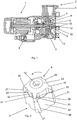
- the driven by an electric motor 1 centrifugal pump 2 of Fig. 1 has a arranged in a housing 3 on a shaft 4 impeller 5.
- a comminution device consisting of a cutting head 6 and a cutting insert 7, respectively.
- the cutting insert 7 is connected by screws 8 to the housing 3.
- a header or attachment 9 is arranged, are formed starting from the blades 10.
- Both the attachment 9 and the cutting head 6 have central bores 12 and 13.
- a connecting means 14 shown here as a screw, the attachment 9 and the cutting head 6 are connected to the impeller 5 and secured thereto.
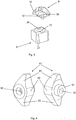
- Fig. 2 shows the cutting head 6 and arranged on this wing attachment 9 in a perspective view.
- the cutting head 6 has between its webs 21 convex-like recesses 22. These form with the - not shown - cutting insert 7 annular segments that represent passageways for a provided with fibrous or lumpy admixtures conveying medium.
- the wing cap 9 has a rotationally symmetrical base body 23, which is formed here from a combination of a truncated cone 24 and a cylinder 25, on.
- the essay has 9 a plurality of symmetrical blades, which are designed as profiled wings 10 and extend from the base body 23 in the radial direction. The profile thickness of the wings 10 decreases radially to the outer diameter of the attachment 9 back.
- Wing contours 29 and 31 are designed tapered relative to the wing normal.
- the wing normals are normal to the axis of rotation of the essay, which pass through the wings at their outer diameter center. Due to the profiled wing 10, it is possible to influence the flow through the attachment 9 during its rotation with the cutting head in the direction of the arrow only in so far as it is necessary for an effect to be introduced.
- the wings 10 of the cutting head 6 have a falling toward the outer diameter of the cutting head 6 course, which has at the end perpendicular sections 27.
- the outer contour of the attachment 9 is adapted in this illustration to the cutting head 6.
- the wing thickness on the outer diameter of the attachment 9 corresponds approximately to the width of the webs 21 of the cutting head at its end face.
- the wings are arranged approximately congruent to one or more cutting head webs 21 with their cutting edges 28. It is crucial that the wings 10 do not cover the cutting edges 28 during operation of the centrifugal pump.
- both the direction of rotation facing the wing contour 29, so the wing contour of one of the direction of rotation facing wing portion 30 and the direction of rotation away from the wing contour 31 have a radius of curvature 32.
- a - not shown here - connecting means can be introduced into the bore 12 to attach the attachment 9 and the cutting head 6 on the impeller 5.
- Fig. 3 shows the cutting head 6 and the attachment 9 separated from each other, whereby the attachment 9 is visible in a perspective bottom view.
- the underside of the attachment 9 is adapted to the suction-side contour of the cutting head 6.
- a pin 33 serves for fitting in a receptacle 34 on the cutting head 6.
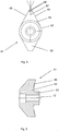
- Fig. 4 shows another, two-winged wing attachment 41 in a perspective view.
- the wing cap 41 has a similar to the main body 23 of the Fig. 2 designed truncated cone / cylindrical base body 42, starting from which two wings 43 are formed.
- the attachment 41 has a bore 12 and its underside is adapted to the frontal contour of a cutting head.
- the wing cap 41 has a pin 33 which is in a - not shown receptacle - a cutting head can be fitted.
- Fig. 5 shows the same wing attachment 41 in plan view.
- the main body 42 is illustrated by a circular line 44.
- the wing thickness of the wings 43 decreases in the radial direction to the outside.
- the wing attachment 41 is designed symmetrically.
- the transition of the wing contours 45, 46 on the base body 42 of the attachment 41 is tangentially such that the wing contours 45, 46 extend from the base body 42 to the outer diameter straight. Due to a decreasing distance of the wing contour from a vane normal 47, the flow control of a vane 43 is made uniform from its elevation from the base body 42 to the outer diameter of the attachment 41.
- Additives are repeatedly donned by the attachment 41 before passing through the cutting device and / or erected in front of the cutting device in order to improve its entry into the cutting device or its supply to the cutting device.
- the tangents to the wing contours 45, 46 with the wing normal 47 of the attachment 41 each include angles 48 equal to or greater than a minimum angle.
- the minimum angle may be dependent on the ratio of the radius of the attachment 41 to the radius of the base body 42 and / or the profile thickness of the wings 43 on the outer diameter of the attachment 41. It has proven to be advantageous that the tangents to the wing contours 45, 46 with the wing normal 47 include an angle of at least 10 degrees.
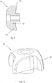
- wing cap 41 is shown in sectional view.
- the attachment 41 is adapted to the underside 49 of the frontal contour of a cutting head and has a pin 33 which can be fitted in a receptacle on the cutting head.
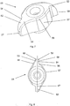
- Fig. 7 shows another wing cap 51 with asymmetrically shaped wings 52 in a perspective view.
- the attachment 51 has a mushroom-shaped basic body 57.
- the attachment 51 is equipped with wings 52, each having a direction of rotation facing the wing portion 53 and a direction of rotation facing away from the wing portion 54.
- the attachment 51 has in rounded areas of its contours partially rounded edges 59th
- Fig. 8 shows the wing cap 51 in plan view.
- the wings 52 of the wing cap 51 are designed profiled according to the invention.
- the profile thickness decreases substantially radially only towards the direction of rotation facing wing portion 53 toward the outside.
- the transition of the direction of rotation facing wing contour 55 on the body 57 of the attachment 51 is tangential with a straight to the outer diameter of the attachment 51 extending wing contour 55.
- the wing contour may also have a radius of curvature.
- the wing contour 55 in the region of the outer diameter of the attachment 51 has a rounding radius 60.
- the attachment 51 In contrast, has a wing contour 56 of the direction of rotation away from the wing portion 54 a tear-off edge 58, which runs straight here, on.
- the wing shape of the direction of rotation is averted Wing section 54 through a recess.
- the tear-off edge 58 which can also be embodied as an undercut in a modified form, the attachment 51 generates, during its rotation, vertebrae which detach from the tear-off edge 58 and / or an undercut edge. The vortex formation assists in loosening the resulting clogging.
- the wings 52 are also supported by the special design of the wings 52, which is evident from the sectional view of the attachment 51 in FIG Fig. 9 is apparent.
- the main body 56 of the attachment 51 is mushroom-shaped.
- the wings 52 have a decreasing to the outer diameter of the attachment 51 course with a stronger curvature, which opens in the region of the outer diameter in a vertical section 27.
- Fig. 10 shows a deducible from the article 51, four-winged attachment 61 with asymmetrically shaped wings 62 in a perspective view.
- Fig. 11 shows in plan view as a further modification an attachment 65, which arises from the attachment 61, characterized in that at two opposite wings 63, the direction of rotation away from the wing portions are each provided with a projection 64.
- Such an approach can be designed in various ways. Provided, for example, an approach that is recognized only in an outer region of a wing. This can also be designed with sharp edges and support a local vortex formation. To influence a pump characteristic, it makes sense to extend the approach over a larger portion along the tower. As a result, a more or less large passage cross section between the cutting head and cutting ring is covered. A cover of the effective passage cross-section leads to a change in the delivery characteristic of the pump.
- the essays are designed to be interchangeable. This results in the advantages already mentioned.
- the invention is however not limited thereto, but also includes with the cutting head cohesively connected essays.
Landscapes
- Engineering & Computer Science (AREA)
- Mechanical Engineering (AREA)
- General Engineering & Computer Science (AREA)
- Structures Of Non-Positive Displacement Pumps (AREA)
- Crushing And Pulverization Processes (AREA)
Claims (14)
- Pompe centrifuge (2) comprenant un dispositif de broyage monté en amont de la roue mobile de la pompe (5), pour des mélanges fibreux ou en fragments dans le liquide refoulé, le dispositif de broyage étant formé par une tête de coupe (6) tournant avec la roue mobile de la pompe (5), pourvue de plusieurs arêtes de coupe (28), et un insert de coupe (7) coopérant avec la tête de coupe (6), disposé de manière fixe dans le boîtier de la pompe centrifuge (2), la tête de coupe (6) étant pourvue de plusieurs évidements (22) limités par des nervures (21), s'étendant essentiellement axialement, une ou plusieurs aubes étant disposées au niveau du côté frontal côté aspiration de la tête de coupe (6), caractérisée en ce qu'un chapeau (9, 41, 51, 61, 65) est disposé du côté frontal côté aspiration de la tête de coupe (6), le côté inférieur (49) du chapeau (9, 41, 51, 61, 65) étant adapté au contour côté aspiration de la tête de coupe (6), le chapeau (9, 41, 51, 61, 65) présentant un corps de base à symétrie de révolution (23, 42, 57), à partir duquel sont réalisées les aubes, au moins une aube étant configurée sous forme de pale profilée (10, 43, 52, 62, 63), au moins l'épaisseur de profilé d'une portion de pale tournée dans le sens de rotation (30, 53) de l'au moins une pale (10, 43, 52, 62, 63) diminuant radialement vers l'extérieur.
- Pompe centrifuge selon la revendication 1, caractérisée en ce que, vu de dessus, les tangentes au contour de pale (29, 31, 45, 46, 55, 56) d'au moins la portion de pale tournée dans le sens de rotation (30, 53) forment avec une perpendiculaire à la pale (47) au moins un angle minimal.
- Pompe centrifuge selon la revendication 2, caractérisée en ce que, vu de dessus, les tangentes au contour de pale (29, 31, 45, 46, 55, 56) d'au moins la portion de pale tournée dans le sens de rotation (30, 53) forment avec une perpendiculaire à la pale (47) un angle d'au moins 10 degrés.
- Pompe centrifuge selon l'une quelconque des revendications 1 à 3, caractérisée en ce que, vu de dessus, la transition du contour de pale tourné dans le sens de rotation (29, 45, 55) au corps de base (23, 42, 57) du chapeau (9, 41, 51, 61, 65) s'effectue tangentiellement.
- Pompe centrifuge selon la revendication 4, caractérisée en ce que le contour de pale tourné dans le sens de rotation (29, 45, 55) s'étend en ligne droite.
- Pompe centrifuge selon la revendication 4, caractérisée en ce que le contour de pale tourné dans le sens de rotation (29, 45, 55) présente un rayon de courbure (32).
- Pompe centrifuge selon l'une quelconque des revendications 1 à 6, caractérisée en ce que le contour extérieur du chapeau (9, 41, 51, 61, 65) est adapté à la tête de coupe (6).
- Pompe centrifuge selon l'une quelconque des revendications 1 à 7, caractérisée en ce que le contour de pale (31, 46, 56) d'une portion de pale opposée au sens de rotation (54) présente un bord d'arrachement (58) et/ou une contre-dépouille.
- Pompe centrifuge selon l'une quelconque des revendications 1 à 8, caractérisée en ce que les pales (10, 43, 52, 62, 63) présentent vers le diamètre extérieur du chapeau (9, 41, 51, 61, 65) une allure descendante avec une courbure de plus en plus forte et/ou une ou plusieurs portions s'étendant verticalement (27).
- Pompe centrifuge selon l'une quelconque des revendications 1 à 9, caractérisée en ce que l'épaisseur de pale au niveau du diamètre extérieur du chapeau (9, 41, 51, 61, 65) est inférieure ou égale à la largeur des nervures de la tête de coupe (6) sur son côté frontal.
- Pompe centrifuge selon l'une quelconque des revendications 1 à 10, caractérisée en ce que le chapeau (9, 41, 51, 61, 65) est disposé avec ses pales (10, 43, 52, 62, 63) sur la tête de coupe (6) de telle sorte que les pales (10, 43, 52, 62, 63) soient disposées approximativement en coïncidence avec une ou plusieurs nervures de tête de coupe (21), les pales (10, 43, 52, 62, 63) ne recouvrant pas les arêtes de coupe (28).
- Pompe centrifuge selon l'une quelconque des revendications 1 à 11, caractérisée en ce que le contour de pale (31, 46, 56) de la portion de pale opposée au sens de rotation (54) présente une pièce rapportée (64).
- Pompe centrifuge (2) comprenant un dispositif de broyage monté en amont de la roue mobile de la pompe (5), pour des mélanges fibreux ou en fragments dans le liquide refoulé, le dispositif de broyage étant formé par une tête de coupe (6) tournant avec la roue mobile de la pompe (5) pourvue de plusieurs arêtes de coupe (28), et un insert de coupe (7) coopérant avec la tête de coupe (6), disposé de manière fixe dans le boîtier de la pompe centrifuge (2), la tête de coupe (6) étant pourvue de plusieurs évidements (22) limités par des nervures (21), s'étendant essentiellement axialement, une ou plusieurs aubes étant disposées au niveau du côté frontal côté aspiration de la tête de coupe (6), caractérisée en ce que les aubes sont réalisées au niveau d'un chapeau (9, 41, 51, 61, 65), les aubes étant configurées éventuellement sous forme de pales profilées (10, 43, 52, 62, 63), le chapeau (9, 41, 51, 61, 65) pouvant être amené en prise par engagement par correspondance de formes avec la tête de coupe (6) et pouvant être connecté à la tête de coupe (6), le chapeau (9, 41, 51, 61, 65) présentant un corps de base (23, 42, 57) pourvu d'un alésage (12) et étant adapté sur son côté inférieur (49) au contour du côté frontal de la tête de coupe (6).
- Pompe centrifuge selon la revendication 13, caractérisée en ce que le chapeau (9, 41, 51, 61, 65) présente un tourillon (33) qui peut être ajusté dans un évidement (34) au niveau de la tête de coupe (6).
Applications Claiming Priority (1)
| Application Number | Priority Date | Filing Date | Title |
|---|---|---|---|
| DE102008021767A DE102008021767A1 (de) | 2008-04-30 | 2008-04-30 | Kreiselpumpe mit Zerkleinerungseinrichtung |
Publications (3)
| Publication Number | Publication Date |
|---|---|
| EP2113670A2 EP2113670A2 (fr) | 2009-11-04 |
| EP2113670A3 EP2113670A3 (fr) | 2010-07-28 |
| EP2113670B1 true EP2113670B1 (fr) | 2016-12-07 |
Family
ID=40547927
Family Applications (1)
| Application Number | Title | Priority Date | Filing Date |
|---|---|---|---|
| EP09004420.7A Active EP2113670B1 (fr) | 2008-04-30 | 2009-03-27 | Pompe centrifuge avec un dispositif de broyage |
Country Status (3)
| Country | Link |
|---|---|
| EP (1) | EP2113670B1 (fr) |
| CN (1) | CN101571135B (fr) |
| DE (1) | DE102008021767A1 (fr) |
Families Citing this family (3)
| Publication number | Priority date | Publication date | Assignee | Title |
|---|---|---|---|---|
| DE102011114495A1 (de) * | 2011-09-29 | 2013-04-04 | Ksb Aktiengesellschaft | Misch- und Belüftungsvorrichtung sowie Verfahren zum Mischen und Belüften |
| ES2744195T3 (es) * | 2016-10-18 | 2020-02-24 | Xylem Europe Gmbh | Rueda cortadora, disco cortador, así como conjunto cortador, adecuados para bombas trituradoras |
| AU2018241189B2 (en) * | 2017-10-05 | 2024-11-07 | KETO Pump Technology Services Pty Ltd | Centrifugal Pump |
Family Cites Families (13)
| Publication number | Priority date | Publication date | Assignee | Title |
|---|---|---|---|---|
| GB1425821A (en) * | 1971-12-11 | 1976-02-18 | Wallwin Pumps Ltd | Comminutor |
| JPS5113403A (ja) * | 1974-07-23 | 1976-02-02 | Toyo Denki Kogyosho Co Ltd | Suichuhonpuyokatsutaafuan |
| US4378093A (en) * | 1980-12-11 | 1983-03-29 | Keener Steven M | Grinder pump cutter assembly |
| JPS5838396A (ja) * | 1981-08-29 | 1983-03-05 | Ebara Corp | グラインダ−ポンプ |
| SE444969B (sv) * | 1982-10-11 | 1986-05-20 | Flygt Ab | Centrifugalpump avseddd for pumpning av vetskor innehallande fasta partiklar |
| DE4128281A1 (de) * | 1991-08-27 | 1993-03-04 | Abs Pumpen Ag | Pumpenaggregat |
| US5460482A (en) * | 1992-05-26 | 1995-10-24 | Vaughan Co., Inc. | Centrifugal chopper pump with internal cutter |
| US5302082A (en) * | 1992-07-09 | 1994-04-12 | Arde, Inc. | Improved efficiency grinding pump for slurry |
| US6190121B1 (en) * | 1999-02-12 | 2001-02-20 | Hayward Gordon Limited | Centrifugal pump with solids cutting action |
| ATE268436T1 (de) | 2002-03-14 | 2004-06-15 | Ksb Ag | Kreiselpumpe mit zerkleinerungseinrichtung |
| DE102004007739A1 (de) * | 2004-02-16 | 2005-08-25 | Wilo Ag | Schneidwerk einer Kreiselpumpe |
| DE102004058458B3 (de) * | 2004-12-03 | 2006-05-18 | Brinkmann Pumpen K.H. Brinkmann Gmbh & Co. Kg | Pumpe mit Schneidlaufrad |
| CN2929263Y (zh) * | 2006-06-08 | 2007-08-01 | 上海连成(集团)有限公司 | 具有切割和反冲洗双重功效的污水泵 |
-
2008
- 2008-04-30 DE DE102008021767A patent/DE102008021767A1/de not_active Withdrawn
-
2009
- 2009-03-27 EP EP09004420.7A patent/EP2113670B1/fr active Active
- 2009-04-30 CN CN2009101379387A patent/CN101571135B/zh not_active Expired - Fee Related
Non-Patent Citations (1)
| Title |
|---|
| None * |
Also Published As
| Publication number | Publication date |
|---|---|
| EP2113670A3 (fr) | 2010-07-28 |
| EP2113670A2 (fr) | 2009-11-04 |
| CN101571135A (zh) | 2009-11-04 |
| DE102008021767A1 (de) | 2009-11-05 |
| CN101571135B (zh) | 2013-05-29 |
Similar Documents
| Publication | Publication Date | Title |
|---|---|---|
| DE10327574B4 (de) | Laufrad für eine Kraftstoffpumpe | |
| EP3779201B1 (fr) | Élément de raclage pour bords d'attaque de roue à aubes pour des pompes à eau | |
| EP3670920B1 (fr) | Dispositif d'aspiration pour une pompe immergée à eaux usées | |
| EP2113670B1 (fr) | Pompe centrifuge avec un dispositif de broyage | |
| EP2168893B1 (fr) | Vanne à roue cellulaire avec élément de broyage | |
| DE69731091T2 (de) | Rotodynamische pumpe | |
| EP3897319B1 (fr) | Broyeur comprenant des protubérances de broyage courbées de manière convexe | |
| EP3922855A1 (fr) | Roue pour une pompe centrifuge | |
| EP1344944B1 (fr) | Pompe centrifuge avec un dispositif de broyage | |
| EP3515602B1 (fr) | Broyeur fin | |
| EP1059381B1 (fr) | Rotor pour un pulpeur | |
| DE20115516U1 (de) | Kreiselpumpe | |
| DE2943567A1 (de) | Reisszahnwalze und damit bestueckte reisswalenzerkleinerungsmaschinen | |
| DE649668C (de) | Laeufer fuer hydraulische Maschinen | |
| EP2535590A2 (fr) | Pompe centrifuge avec barre de coupe intégrée | |
| EP1161630B1 (fr) | Pompe de broyage | |
| DE10030957C1 (de) | Kreiskolbenpumpe | |
| DE3432255A1 (de) | Mehrstufige zerkleinerungsvorrichtung, insbesondere fuer schwer reissbare plastikfolien, gummiregenerate oder dergleichen | |
| DE10305726A1 (de) | Kreiselpumpe mit Zerkleinerungseinrichtung | |
| WO2020156805A1 (fr) | Rotor pour un dispositif destiné à mélanger de la poudre et du liquide et dispositif pour mélanger de la poudre et du liquide | |
| LU102842B1 (de) | Schneidkopf einer Pumpe | |
| DE19802025C1 (de) | Zerkleinerungspumpe | |
| EP2639459B1 (fr) | Pompe pour suspensions fixes et liquides | |
| EP4108935A1 (fr) | Bague coupante d'une pompe pour liquide chargé de solide | |
| DE2229650A1 (de) | Zerreisswerk, insbesondere zum zerkleinern von fliessmist |
Legal Events
| Date | Code | Title | Description |
|---|---|---|---|
| PUAI | Public reference made under article 153(3) epc to a published international application that has entered the european phase |
Free format text: ORIGINAL CODE: 0009012 |
|
| AK | Designated contracting states |
Kind code of ref document: A2 Designated state(s): AT BE BG CH CY CZ DE DK EE ES FI FR GB GR HR HU IE IS IT LI LT LU LV MC MK MT NL NO PL PT RO SE SI SK TR |
|
| AX | Request for extension of the european patent |
Extension state: AL BA RS |
|
| PUAL | Search report despatched |
Free format text: ORIGINAL CODE: 0009013 |
|
| AK | Designated contracting states |
Kind code of ref document: A3 Designated state(s): AT BE BG CH CY CZ DE DK EE ES FI FR GB GR HR HU IE IS IT LI LT LU LV MC MK MT NL NO PL PT RO SE SI SK TR |
|
| AX | Request for extension of the european patent |
Extension state: AL BA RS |
|
| 17P | Request for examination filed |
Effective date: 20110119 |
|
| AKX | Designation fees paid |
Designated state(s): AT BE BG CH CY CZ DE DK EE ES FI FR GB GR HR HU IE IS IT LI LT LU LV MC MK MT NL NO PL PT RO SE SI SK TR |
|
| GRAP | Despatch of communication of intention to grant a patent |
Free format text: ORIGINAL CODE: EPIDOSNIGR1 |
|
| INTG | Intention to grant announced |
Effective date: 20160809 |
|
| GRAS | Grant fee paid |
Free format text: ORIGINAL CODE: EPIDOSNIGR3 |
|
| GRAA | (expected) grant |
Free format text: ORIGINAL CODE: 0009210 |
|
| AK | Designated contracting states |
Kind code of ref document: B1 Designated state(s): AT BE BG CH CY CZ DE DK EE ES FI FR GB GR HR HU IE IS IT LI LT LU LV MC MK MT NL NO PL PT RO SE SI SK TR |
|
| REG | Reference to a national code |
Ref country code: GB Ref legal event code: FG4D Free format text: NOT ENGLISH |
|
| REG | Reference to a national code |
Ref country code: CH Ref legal event code: EP Ref country code: AT Ref legal event code: REF Ref document number: 852000 Country of ref document: AT Kind code of ref document: T Effective date: 20161215 |
|
| REG | Reference to a national code |
Ref country code: IE Ref legal event code: FG4D Free format text: LANGUAGE OF EP DOCUMENT: GERMAN |
|
| REG | Reference to a national code |
Ref country code: DE Ref legal event code: R096 Ref document number: 502009013446 Country of ref document: DE |
|
| PG25 | Lapsed in a contracting state [announced via postgrant information from national office to epo] |
Ref country code: LV Free format text: LAPSE BECAUSE OF FAILURE TO SUBMIT A TRANSLATION OF THE DESCRIPTION OR TO PAY THE FEE WITHIN THE PRESCRIBED TIME-LIMIT Effective date: 20161207 |
|
| REG | Reference to a national code |
Ref country code: FR Ref legal event code: PLFP Year of fee payment: 9 |
|
| REG | Reference to a national code |
Ref country code: LT Ref legal event code: MG4D |
|
| REG | Reference to a national code |
Ref country code: NL Ref legal event code: MP Effective date: 20161207 |
|
| PG25 | Lapsed in a contracting state [announced via postgrant information from national office to epo] |
Ref country code: SE Free format text: LAPSE BECAUSE OF FAILURE TO SUBMIT A TRANSLATION OF THE DESCRIPTION OR TO PAY THE FEE WITHIN THE PRESCRIBED TIME-LIMIT Effective date: 20161207 Ref country code: NO Free format text: LAPSE BECAUSE OF FAILURE TO SUBMIT A TRANSLATION OF THE DESCRIPTION OR TO PAY THE FEE WITHIN THE PRESCRIBED TIME-LIMIT Effective date: 20170307 Ref country code: LT Free format text: LAPSE BECAUSE OF FAILURE TO SUBMIT A TRANSLATION OF THE DESCRIPTION OR TO PAY THE FEE WITHIN THE PRESCRIBED TIME-LIMIT Effective date: 20161207 Ref country code: GR Free format text: LAPSE BECAUSE OF FAILURE TO SUBMIT A TRANSLATION OF THE DESCRIPTION OR TO PAY THE FEE WITHIN THE PRESCRIBED TIME-LIMIT Effective date: 20170308 |
|
| PG25 | Lapsed in a contracting state [announced via postgrant information from national office to epo] |
Ref country code: HR Free format text: LAPSE BECAUSE OF FAILURE TO SUBMIT A TRANSLATION OF THE DESCRIPTION OR TO PAY THE FEE WITHIN THE PRESCRIBED TIME-LIMIT Effective date: 20161207 Ref country code: ES Free format text: LAPSE BECAUSE OF FAILURE TO SUBMIT A TRANSLATION OF THE DESCRIPTION OR TO PAY THE FEE WITHIN THE PRESCRIBED TIME-LIMIT Effective date: 20161207 Ref country code: FI Free format text: LAPSE BECAUSE OF FAILURE TO SUBMIT A TRANSLATION OF THE DESCRIPTION OR TO PAY THE FEE WITHIN THE PRESCRIBED TIME-LIMIT Effective date: 20161207 |
|
| PG25 | Lapsed in a contracting state [announced via postgrant information from national office to epo] |
Ref country code: NL Free format text: LAPSE BECAUSE OF FAILURE TO SUBMIT A TRANSLATION OF THE DESCRIPTION OR TO PAY THE FEE WITHIN THE PRESCRIBED TIME-LIMIT Effective date: 20161207 |
|
| PG25 | Lapsed in a contracting state [announced via postgrant information from national office to epo] |
Ref country code: RO Free format text: LAPSE BECAUSE OF FAILURE TO SUBMIT A TRANSLATION OF THE DESCRIPTION OR TO PAY THE FEE WITHIN THE PRESCRIBED TIME-LIMIT Effective date: 20161207 Ref country code: CZ Free format text: LAPSE BECAUSE OF FAILURE TO SUBMIT A TRANSLATION OF THE DESCRIPTION OR TO PAY THE FEE WITHIN THE PRESCRIBED TIME-LIMIT Effective date: 20161207 Ref country code: SK Free format text: LAPSE BECAUSE OF FAILURE TO SUBMIT A TRANSLATION OF THE DESCRIPTION OR TO PAY THE FEE WITHIN THE PRESCRIBED TIME-LIMIT Effective date: 20161207 Ref country code: IS Free format text: LAPSE BECAUSE OF FAILURE TO SUBMIT A TRANSLATION OF THE DESCRIPTION OR TO PAY THE FEE WITHIN THE PRESCRIBED TIME-LIMIT Effective date: 20170407 Ref country code: EE Free format text: LAPSE BECAUSE OF FAILURE TO SUBMIT A TRANSLATION OF THE DESCRIPTION OR TO PAY THE FEE WITHIN THE PRESCRIBED TIME-LIMIT Effective date: 20161207 |
|
| PG25 | Lapsed in a contracting state [announced via postgrant information from national office to epo] |
Ref country code: PL Free format text: LAPSE BECAUSE OF FAILURE TO SUBMIT A TRANSLATION OF THE DESCRIPTION OR TO PAY THE FEE WITHIN THE PRESCRIBED TIME-LIMIT Effective date: 20161207 Ref country code: BG Free format text: LAPSE BECAUSE OF FAILURE TO SUBMIT A TRANSLATION OF THE DESCRIPTION OR TO PAY THE FEE WITHIN THE PRESCRIBED TIME-LIMIT Effective date: 20170307 Ref country code: PT Free format text: LAPSE BECAUSE OF FAILURE TO SUBMIT A TRANSLATION OF THE DESCRIPTION OR TO PAY THE FEE WITHIN THE PRESCRIBED TIME-LIMIT Effective date: 20170407 Ref country code: IT Free format text: LAPSE BECAUSE OF FAILURE TO SUBMIT A TRANSLATION OF THE DESCRIPTION OR TO PAY THE FEE WITHIN THE PRESCRIBED TIME-LIMIT Effective date: 20161207 |
|
| REG | Reference to a national code |
Ref country code: DE Ref legal event code: R097 Ref document number: 502009013446 Country of ref document: DE |
|
| PLBE | No opposition filed within time limit |
Free format text: ORIGINAL CODE: 0009261 |
|
| STAA | Information on the status of an ep patent application or granted ep patent |
Free format text: STATUS: NO OPPOSITION FILED WITHIN TIME LIMIT |
|
| REG | Reference to a national code |
Ref country code: CH Ref legal event code: PL |
|
| 26N | No opposition filed |
Effective date: 20170908 |
|
| GBPC | Gb: european patent ceased through non-payment of renewal fee |
Effective date: 20170327 |
|
| PG25 | Lapsed in a contracting state [announced via postgrant information from national office to epo] |
Ref country code: SI Free format text: LAPSE BECAUSE OF FAILURE TO SUBMIT A TRANSLATION OF THE DESCRIPTION OR TO PAY THE FEE WITHIN THE PRESCRIBED TIME-LIMIT Effective date: 20161207 Ref country code: MC Free format text: LAPSE BECAUSE OF FAILURE TO SUBMIT A TRANSLATION OF THE DESCRIPTION OR TO PAY THE FEE WITHIN THE PRESCRIBED TIME-LIMIT Effective date: 20161207 Ref country code: DK Free format text: LAPSE BECAUSE OF FAILURE TO SUBMIT A TRANSLATION OF THE DESCRIPTION OR TO PAY THE FEE WITHIN THE PRESCRIBED TIME-LIMIT Effective date: 20161207 |
|
| REG | Reference to a national code |
Ref country code: IE Ref legal event code: MM4A |
|
| REG | Reference to a national code |
Ref country code: DE Ref legal event code: R081 Ref document number: 502009013446 Country of ref document: DE Owner name: KSB SE & CO. KGAA, DE Free format text: FORMER OWNER: KSB AKTIENGESELLSCHAFT, 67227 FRANKENTHAL, DE |
|
| PG25 | Lapsed in a contracting state [announced via postgrant information from national office to epo] |
Ref country code: LU Free format text: LAPSE BECAUSE OF NON-PAYMENT OF DUE FEES Effective date: 20170327 |
|
| PG25 | Lapsed in a contracting state [announced via postgrant information from national office to epo] |
Ref country code: CH Free format text: LAPSE BECAUSE OF NON-PAYMENT OF DUE FEES Effective date: 20170331 Ref country code: LI Free format text: LAPSE BECAUSE OF NON-PAYMENT OF DUE FEES Effective date: 20170331 Ref country code: GB Free format text: LAPSE BECAUSE OF NON-PAYMENT OF DUE FEES Effective date: 20170327 Ref country code: IE Free format text: LAPSE BECAUSE OF NON-PAYMENT OF DUE FEES Effective date: 20170327 |
|
| REG | Reference to a national code |
Ref country code: BE Ref legal event code: MM Effective date: 20170331 |
|
| REG | Reference to a national code |
Ref country code: FR Ref legal event code: PLFP Year of fee payment: 10 |
|
| REG | Reference to a national code |
Ref country code: AT Ref legal event code: MM01 Ref document number: 852000 Country of ref document: AT Kind code of ref document: T Effective date: 20170327 |
|
| PG25 | Lapsed in a contracting state [announced via postgrant information from national office to epo] |
Ref country code: BE Free format text: LAPSE BECAUSE OF NON-PAYMENT OF DUE FEES Effective date: 20170331 |
|
| PG25 | Lapsed in a contracting state [announced via postgrant information from national office to epo] |
Ref country code: AT Free format text: LAPSE BECAUSE OF NON-PAYMENT OF DUE FEES Effective date: 20170327 |
|
| PG25 | Lapsed in a contracting state [announced via postgrant information from national office to epo] |
Ref country code: MT Free format text: LAPSE BECAUSE OF FAILURE TO SUBMIT A TRANSLATION OF THE DESCRIPTION OR TO PAY THE FEE WITHIN THE PRESCRIBED TIME-LIMIT Effective date: 20161207 |
|
| PG25 | Lapsed in a contracting state [announced via postgrant information from national office to epo] |
Ref country code: HU Free format text: LAPSE BECAUSE OF FAILURE TO SUBMIT A TRANSLATION OF THE DESCRIPTION OR TO PAY THE FEE WITHIN THE PRESCRIBED TIME-LIMIT; INVALID AB INITIO Effective date: 20090327 |
|
| PG25 | Lapsed in a contracting state [announced via postgrant information from national office to epo] |
Ref country code: CY Free format text: LAPSE BECAUSE OF NON-PAYMENT OF DUE FEES Effective date: 20161207 |
|
| PG25 | Lapsed in a contracting state [announced via postgrant information from national office to epo] |
Ref country code: MK Free format text: LAPSE BECAUSE OF FAILURE TO SUBMIT A TRANSLATION OF THE DESCRIPTION OR TO PAY THE FEE WITHIN THE PRESCRIBED TIME-LIMIT Effective date: 20161207 |
|
| PG25 | Lapsed in a contracting state [announced via postgrant information from national office to epo] |
Ref country code: TR Free format text: LAPSE BECAUSE OF FAILURE TO SUBMIT A TRANSLATION OF THE DESCRIPTION OR TO PAY THE FEE WITHIN THE PRESCRIBED TIME-LIMIT Effective date: 20161207 |
|
| P01 | Opt-out of the competence of the unified patent court (upc) registered |
Effective date: 20230712 |
|
| PGFP | Annual fee paid to national office [announced via postgrant information from national office to epo] |
Ref country code: DE Payment date: 20240328 Year of fee payment: 16 |
|
| REG | Reference to a national code |
Ref country code: DE Ref legal event code: R119 Ref document number: 502009013446 Country of ref document: DE |
|
| PG25 | Lapsed in a contracting state [announced via postgrant information from national office to epo] |
Ref country code: DE Free format text: LAPSE BECAUSE OF NON-PAYMENT OF DUE FEES Effective date: 20251001 |
|
| PGFP | Annual fee paid to national office [announced via postgrant information from national office to epo] |
Ref country code: FR Payment date: 20260330 Year of fee payment: 18 |