EP2113703B1 - Scellage de tube haute pression - Google Patents
Scellage de tube haute pression Download PDFInfo
- Publication number
- EP2113703B1 EP2113703B1 EP09004822.4A EP09004822A EP2113703B1 EP 2113703 B1 EP2113703 B1 EP 2113703B1 EP 09004822 A EP09004822 A EP 09004822A EP 2113703 B1 EP2113703 B1 EP 2113703B1
- Authority
- EP
- European Patent Office
- Prior art keywords
- seal
- tube
- pair
- recessed groove
- extrusion
- Prior art date
- Legal status (The legal status is an assumption and is not a legal conclusion. Google has not performed a legal analysis and makes no representation as to the accuracy of the status listed.)
- Active
Links
Images


Classifications
-
- F—MECHANICAL ENGINEERING; LIGHTING; HEATING; WEAPONS; BLASTING
- F16—ENGINEERING ELEMENTS AND UNITS; GENERAL MEASURES FOR PRODUCING AND MAINTAINING EFFECTIVE FUNCTIONING OF MACHINES OR INSTALLATIONS; THERMAL INSULATION IN GENERAL
- F16L—PIPES; JOINTS OR FITTINGS FOR PIPES; SUPPORTS FOR PIPES, CABLES OR PROTECTIVE TUBING; MEANS FOR THERMAL INSULATION IN GENERAL
- F16L21/00—Joints with sleeve or socket
- F16L21/02—Joints with sleeve or socket with elastic sealing rings between pipe and sleeve or between pipe and socket, e.g. with rolling or other prefabricated profiled rings
- F16L21/022—Joints with sleeve or socket with elastic sealing rings between pipe and sleeve or between pipe and socket, e.g. with rolling or other prefabricated profiled rings used with sleeves or nipples for pipes of the same diameter, or with reduction pieces
-
- F—MECHANICAL ENGINEERING; LIGHTING; HEATING; WEAPONS; BLASTING
- F16—ENGINEERING ELEMENTS AND UNITS; GENERAL MEASURES FOR PRODUCING AND MAINTAINING EFFECTIVE FUNCTIONING OF MACHINES OR INSTALLATIONS; THERMAL INSULATION IN GENERAL
- F16L—PIPES; JOINTS OR FITTINGS FOR PIPES; SUPPORTS FOR PIPES, CABLES OR PROTECTIVE TUBING; MEANS FOR THERMAL INSULATION IN GENERAL
- F16L21/00—Joints with sleeve or socket
- F16L21/02—Joints with sleeve or socket with elastic sealing rings between pipe and sleeve or between pipe and socket, e.g. with rolling or other prefabricated profiled rings
- F16L21/035—Joints with sleeve or socket with elastic sealing rings between pipe and sleeve or between pipe and socket, e.g. with rolling or other prefabricated profiled rings placed around the spigot end before connection
-
- F—MECHANICAL ENGINEERING; LIGHTING; HEATING; WEAPONS; BLASTING
- F16—ENGINEERING ELEMENTS AND UNITS; GENERAL MEASURES FOR PRODUCING AND MAINTAINING EFFECTIVE FUNCTIONING OF MACHINES OR INSTALLATIONS; THERMAL INSULATION IN GENERAL
- F16L—PIPES; JOINTS OR FITTINGS FOR PIPES; SUPPORTS FOR PIPES, CABLES OR PROTECTIVE TUBING; MEANS FOR THERMAL INSULATION IN GENERAL
- F16L25/00—Construction or details of pipe joints not provided for in, or of interest apart from, groups F16L13/00 - F16L23/00
- F16L25/14—Joints for pipes of different diameters or cross-section
-
- F—MECHANICAL ENGINEERING; LIGHTING; HEATING; WEAPONS; BLASTING
- F16—ENGINEERING ELEMENTS AND UNITS; GENERAL MEASURES FOR PRODUCING AND MAINTAINING EFFECTIVE FUNCTIONING OF MACHINES OR INSTALLATIONS; THERMAL INSULATION IN GENERAL
- F16L—PIPES; JOINTS OR FITTINGS FOR PIPES; SUPPORTS FOR PIPES, CABLES OR PROTECTIVE TUBING; MEANS FOR THERMAL INSULATION IN GENERAL
- F16L27/00—Adjustable joints; Joints allowing movement
- F16L27/10—Adjustable joints; Joints allowing movement comprising a flexible connection only
- F16L27/1017—Joints with sleeve or socket
-
- F—MECHANICAL ENGINEERING; LIGHTING; HEATING; WEAPONS; BLASTING
- F16—ENGINEERING ELEMENTS AND UNITS; GENERAL MEASURES FOR PRODUCING AND MAINTAINING EFFECTIVE FUNCTIONING OF MACHINES OR INSTALLATIONS; THERMAL INSULATION IN GENERAL
- F16L—PIPES; JOINTS OR FITTINGS FOR PIPES; SUPPORTS FOR PIPES, CABLES OR PROTECTIVE TUBING; MEANS FOR THERMAL INSULATION IN GENERAL
- F16L27/00—Adjustable joints; Joints allowing movement
- F16L27/10—Adjustable joints; Joints allowing movement comprising a flexible connection only
- F16L27/113—Adjustable joints; Joints allowing movement comprising a flexible connection only the ends of the pipe being interconnected by a rigid sleeve
Definitions
- the present disclosure relates to tube seals, and more particularly to a high pressure tube seal.
- WO 2007/145779 A2 discloses tube seals for connecting two components.
- An elastomeric seal body is molded to a rigid cylindrical or conical tube.
- the seal body includes seal bead portions at the ends.
- Current design tube seals are subject to failure due to extrusion at high pressures.
- the present disclosure provides a tube seal, including a rigid cylindrical tube; an elastomeric seal body molded to an outer surface of the cylindrical tube, the elastomeric seal body including a pair of raised seal bead portions at opposite ends of the seal body and a pair of recessed groove portions adjacent to the pair of raised seal bead portions.
- a pair of anti-extrusion rings are disposed in the recessed groove portions.
- the present invention relates to a tube seal, comprising a rigid cylindrical tube and an elastomeric seal body molded to an outer surface of said cylindrical tube, wherein said elastomeric seal body includes a pair of raised seal bead portions at opposite ends of said seal body and a pair of recessed groove portions adjacent to said pair of raised seal bead portions and a pair of anti-extrusion rings disposed in said recessed groove portions.
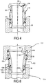
- a tube seal 10 is shown providing a seal connection between a first tube member 12 and a second tube member 14.
- First tube member 12 can include an interior surface 16 and second tube member 14 can include an interior surface 18 and each tube member 12, 14 can include a shoulder portion 20 extending radially inward from surfaces 16, 18, respectively.
- the tube seal 10 sealingly engages against interior surfaces 16 and 18 of first and second tube members 12, 14.
- the tube seal 10 can include a rigid cylindrical tube 22 and an elastomeric seal body 24 molded to an outer surface of the cylindrical tube 22.
- the elastomeric seal body includes a pair of raised seal bead portions 26, 28 at opposite ends of the seal body 24 and a pair of recessed groove portions 30, 32, adjacent to the pair of raised seal bead portions 26, 28.
- a pair of anti-extrusion rings 36, 38 are disposed in the recessed groove portions 30, 32.
- the rigid cylindrical tube 22 includes a radially outwardly extending annular portion 40 disposed between the pair of recessed groove portions 30, 32 of the elastomeric seal body 24.
- the outwardly extending annular portion 40 has an outer diameter preferably larger than an inner diameter of the pair of anti-extrusion rings 36, 38.
- the outwardly extending annular portion 40 of the cylindrical tube can be optionally overmolded with the elastomeric seal body.
- the anti-extrusion rings 36, 38 can include generally cylindrical inner and outer surfaces 36a, 38a; 36b, 38b, respectively, as well as generally planar opposite face surfaces 36c, 38c.
- the tube seal 10 with anti-extrusion rings 36, 38 can accommodate for misalignment of the interior surfaces or bores 16, 18 of tube members 12, 14. As illustrated in Figure 4 , the tube seal 10 can be inserted with an axial misalignment by an angle ⁇ .
- the anti-extrusion rings 36, 38 can be provided with a clearance between the inner diameter 36a and the seal groove outer diameter and a clearance between the outer diameter 36b and the bore diameter to allow angular misalignment.
- the amount of clearance can dictate the amount of angular misalignment that can be accommodated.
- the clearances also provide seal bead extrusion resistance under high pressure.
- the bore diameter is protected from damage due to fretting or scratching and noise created from seal to bore interference due to vibrational influence is also eliminated.
- the tube seal 110 with anti-extrusion rings 36, 38 can be utilized in a diameter reducing tube seal application.
- the diameter reducing tube seal 110 includes a generally conically shaped rigid insert 122 and an elastomeric seal body 124 molded to an outer surface of the rigid conical insert 122. It should be understood that by “generally conically shaped,” it is meant that the insert 122 can have curved walls or stepped walls, as shown, or can have straight walls.
- the metal conical insert 122 includes a first opening 136 at a first end and a second opening 138 at a second end, the first opening 136 is larger in diameter than the second opening 138.
- the elastomeric seal body 124 is molded to the rigid insert 122 so as to create a mechanical connection therebetween.
- the elastomeric seal body 124 includes annular raised bead portions 126, 128 which, as shown in Figure 8 , are shown received in the end portions of tubular members 112, 114 which are of different diameters.
- the elastomeric seal body 124 includes a pair of recessed groove portions 130, 132 adjacent to the pair of raised bead portions 126, 128.
- a pair of anti-extrusion rings 36, 38 are disposed in the recessed groove portions 130, 132.
- the anti-extrusion rings 36, 38 can include split rings such as, for example, scarf cut or butt cut rings, or locking split rings as illustrated in Figures 5-7 . Although the locking split rings are shown in Figures 5-7 for exemplary purposes only, other configurations of locking or unlocking split rings can be utilized.
- the use of split cut rings for anti-extrusion rings 36, 38 helps to facilitate assembly of the anti-extrusion rings 36, 38 on the seal assembly 10-However, it is contemplated that other anti-extrusion rings could be utilized. Further, the ends of the rings 36, 38 could be joined by adhesives or by sonic welding or other joining techniques.
- the anti-extrusion rings 36, 38 can be made from any rigid material including, but not limited to, thermoplastics, thermoset plastics, PTFE, metal, ceramic, or other reinforced materials.
- the high pressure seal of the present disclosure was tested utilizing anti-extrusion rings 36, 38 which were made from Troylon® and compared to current production seals which do not include the anti-extrusion rings disclosed herein.
- the seals were tested on a hydraulic test stand and were subjected to a static pressure and a pressure pulse ramp at room temperature. To establish a baseline, three current production seals were tested with an 8.4 millimeter extrusion gap, applying incremental 1 bar pressure steps until leakage. Under continuous pressure, the three production seals leaked at 24, 26, and 32 bar.
- a high pressure seal according to the present disclosure was then tested at room temperature with an 8.4 millimeter extrusion gap. Initially, a 14 bar continuous pressure was initially applied and was then increased by approximately 3 bar every ten seconds. The pressure was increased to 106 bar and held for one hour before shut down with no leakage present. The same seal was then re-tested with pressure pulsation from 3 bar to 106 bar (five seconds each step). After fifteen minutes at room temperature, the temperature was ramped to 150°C at approximately 100°C, extrusion of the anti-extrusion ring was observed. The testing was stopped and the seal was removed. The backup ring was permanently distorted, however, no damage was evident on the seal and no fluid leakage was evident before the testing was stopped.
- a second seal was tested under the same pressure, pulse, and temperature ramp conditions. Backup ring extrusion at the bore was noted at approximately the same temperature. Seal shift during the pressure pulsing compressed the seal on one end and opened the extrusion gap on the other side, reducing radial support of the backup ring. However, no fluid leakage or seal damage was observed.
- a third seal was then tested with the gap between the bores reduced from 8.4 millimeters to 6.35 millimeters.
- the backup ring extrusion was noted at 120°C. Again, no fluid leakage or seal damage was observed.
- the high pressure seal of the present disclosure out-performed the current production tube seal design by at least four times at room temperature. Although sufficient at room temperature, the backup ring material softens with increased temperature to the point of extrusion. Subsequent part testing using a reinforced backup ring material enabled the seal to maintain a 207 bar pressure pulsation at room temperature. Elevated temperature testing at 150°C resulted in the seal being able to hold 69 bar pulsations indefinitely while holding intermittent peak pressures of 138 bar. Clearly, the high pressure tube seal has been proven to achieve significantly higher pressures than current production designs.
- the analytical testing has proven the functional advantage of the anti-extrusion features over the current production designs under high pressure conditions and with the use of alternative materials and through further testing, it is expected that further improved results can be achieved.
Landscapes
- Engineering & Computer Science (AREA)
- General Engineering & Computer Science (AREA)
- Mechanical Engineering (AREA)
- Gasket Seals (AREA)
Claims (14)
- Scellage de tube (10), comprenant un tube cylindrique rigide (22); un corps de scellage élastomère (24) moulé sur une surface extérieure dudit tube cylindrique (22), ledit corps de scellage élastomère (24) comprenant une paire de parties de bourrelet de scellage surélevées (26, 28) à des extrémités opposées dudit corps de scellage (24) et une paire de parties de rainure évidées (30, 32) adjacentes à ladite paire de parties de bourrelet de scellage surélevées (26, 28); et une paire d'anneaux anti-extrusion (36, 38) disposés dans lesdites parties de rainure évidées (30, 32); caractérisé en ce que ledit tube cylindrique (22) comprend une partie annulaire s'étendant radialement vers l''extérieur (40) qui est disposée entre ladite paire de parties de rainure évidées (30, 32) dudit corps de scellage élastomère (24).
- Scellage de tube selon la revendication 1, dans lequel ladite paire d'anneaux anti-extrusion sont constitués d'une matière plastique.
- Scellage de tube selon l'une des revendications 1 ou 2, dans lequel lesdits anneaux anti-extrusion (36, 38) sont des anneaux fendus.
- Scellage de tube selon l'une des revendications 1 à 3, dans lequel lesdits anneaux anti-extrusion (36, 38) présentent une surface intérieure essentiellement cylindrique (36a, 38a) et une surface extérieure essentiellement cylindrique (36b, 38b).
- Scellage de tube selon la revendication 4, dans lequel un jeu est prévu entre ladite surface intérieure essentiellement cylindrique (36a, 38a) et un diamètre extérieur desdites parties de rainure évidées (30, 32).
- Scellage de tube selon l'une des revendications 1 à 5, dans lequel lesdites parties de bourrelet de scellage surélevées (26, 28) présentent un diamètre plus grand que ladite surface extérieure essentiellement cylindrique (36b, 38b) dudit anneau anti-extrusion (36, 38) reçu dans une partie de rainure évidée adjacente (30, 32).
- Scellage de tube selon l'une des revendications 1 à 6, dans lequel lesdits anneaux anti-extrusion (36, 38) présentent des surfaces latérales essentiellement planes (36c, 38c).
- Scellage de tube (10) comprenant un insert rigide de forme essentiellement conique (122); un corps de scellage élastomère (124) moulé sur une surface extérieure dudit insert rigide de forme essentiellement conique (122), ledit corps de scellage élastomère (124) comprenant une paire de parties de bourrelet de scellage surélevées (126, 128) à des extrémités opposées dudit corps de sellage (124), et une paire de parties de rainure évidées (130, 132) adjacente à ladite paire de parties de bourrelet de scellage surélevées (126, 128); et une paire d'anneaux anti-extrusion (36, 38) disposés dans lesdites parties de rainure évidées (130, 132); caractérisé en ce que ledit tube cylindrique (22) comprend une partie annulaire s'étendant radialement vers l'extérieur (40) qui est disposée entre ladite paire de rainures évidées (30, 32) dudit corps de scellage élastomère (24).
- Scellage de tube selon la revendication 8, dans lequel ladite paire d'anneaux anti-extrusion (36, 38) sont constitués d'une matière plastique.
- Scellage de tube selon l'une des revendications 8 ou 9, dans lequel lesdits anneaux anti-extrusion (36, 38) sont des anneaux fendus.
- Scellage de tube selon l'une des revendications 8 à 10, dans lequel lesdits anneaux anti-extrusion (36, 38) présentent une surface intérieure essentiellement cylindrique (36a, 38a) et une surface extérieure essentiellement cylindrique (36b, 38b).
- Scellage de tube selon la revendication 11, dans lequel un jeu est prévu entre ladite surface intérieure essentiellement cylindrique (36a, 38a) et un diamètre extérieur desdites parties de rainure évidées (130, 132).
- Scellage de tube selon l'une des revendications 8 à 12, dans lequel lesdites parties de bourrelet de scellage surélevées (126, 128) présentent un diamètre plus grand que ladite surface extérieure essentiellement cylindrique (36b, 38b) dudit anneau anti-extrusion (36, 38) reçu dans une partie de rainure évidée adjacente (130, 132).
- Scellage de tube selon l'une des revendications 8 à 13, dans lequel lesdits anneaux anti-extrusion (36, 38) présentent des surfaces latérales essentiellement planes (36c, 38c).
Applications Claiming Priority (1)
| Application Number | Priority Date | Filing Date | Title |
|---|---|---|---|
| US12/110,812 US20090267307A1 (en) | 2008-04-28 | 2008-04-28 | High Pressure Tube Seal |
Publications (3)
| Publication Number | Publication Date |
|---|---|
| EP2113703A2 EP2113703A2 (fr) | 2009-11-04 |
| EP2113703A3 EP2113703A3 (fr) | 2017-01-25 |
| EP2113703B1 true EP2113703B1 (fr) | 2018-06-27 |
Family
ID=41000032
Family Applications (1)
| Application Number | Title | Priority Date | Filing Date |
|---|---|---|---|
| EP09004822.4A Active EP2113703B1 (fr) | 2008-04-28 | 2009-04-01 | Scellage de tube haute pression |
Country Status (2)
| Country | Link |
|---|---|
| US (1) | US20090267307A1 (fr) |
| EP (1) | EP2113703B1 (fr) |
Families Citing this family (10)
| Publication number | Priority date | Publication date | Assignee | Title |
|---|---|---|---|---|
| FR3021388B1 (fr) * | 2014-05-21 | 2017-02-17 | Renault Sa | "ensemble hydraulique a assemblage comportant une etancheite perfectionnee" |
| WO2016036841A1 (fr) * | 2014-09-02 | 2016-03-10 | Actuant Corporation | Raccord de tuyau |
| USD771232S1 (en) * | 2014-10-29 | 2016-11-08 | Stephen A. Coon | Adjustable channel for an air conditioning line set |
| JP6527046B2 (ja) * | 2015-07-27 | 2019-06-05 | タイガースポリマー株式会社 | 管路ブロック接続用コネクタ部材 |
| CA2970712A1 (fr) * | 2016-06-16 | 2017-12-16 | The Ford Meter Box Company, Inc. | Connecteurs sans contact |
| US10788150B2 (en) * | 2018-03-22 | 2020-09-29 | Freudenberg-Nok General Partnership | Tube seal |
| DE102019102934A1 (de) * | 2019-02-06 | 2020-08-06 | Carl Freudenberg Kg | Steckstück und Verwendung des Steckstücks |
| US20220090714A1 (en) * | 2020-09-18 | 2022-03-24 | Trelleborg Sealing Solutions Germany Gmbh | Flexible tube seal |
| US11852270B2 (en) * | 2021-07-30 | 2023-12-26 | Raytheon Company | Compact, blind-mate fluid fitting |
| DE202023104408U1 (de) * | 2023-08-03 | 2023-08-24 | Rusty S. Goyer | Filtermodul |
Family Cites Families (41)
| Publication number | Priority date | Publication date | Assignee | Title |
|---|---|---|---|---|
| US2519436A (en) * | 1946-03-11 | 1950-08-22 | Breeze Corp | Sealing and electrical shielding gasket |
| US2974684A (en) * | 1955-11-25 | 1961-03-14 | Bauer Bros Co | Reinforced molded cone |
| US3501158A (en) * | 1967-07-03 | 1970-03-17 | Cassius L Tillman | Tubular seal |
| US3602531A (en) * | 1969-10-20 | 1971-08-31 | Adjusta Post Mfg Co | Tubing coupler |
| US3979130A (en) * | 1971-06-18 | 1976-09-07 | Fisons Limited | Sleeves |
| US3884510A (en) * | 1971-11-04 | 1975-05-20 | Pont A Mousson | Device for the tensile locking of pipe elements |
| US3995888A (en) * | 1973-05-10 | 1976-12-07 | Mcilroy John C | Flexible pipe connector |
| US3915481A (en) * | 1974-02-01 | 1975-10-28 | Jr Richard O Marsh | Double tapered pipe coupling |
| US4242164A (en) * | 1978-10-13 | 1980-12-30 | Skinner Harry W | Gasket for sealing a pipe in a porthole |
| US4346647A (en) * | 1981-02-20 | 1982-08-31 | Weaver Manufacturing Company | Piston construction for reciprocating pumps |
| US4531711A (en) * | 1982-06-30 | 1985-07-30 | Cameron Iron Works, Inc. | Valve and stem seal therefor |
| JPH0723758B2 (ja) * | 1983-11-22 | 1995-03-15 | 株式会社ブリヂストン | ゴム管状物 |
| US4553759A (en) * | 1984-12-10 | 1985-11-19 | Cameron Iron Works, Inc. | Valve and improved stem seal therefor |
| US4763695A (en) * | 1986-06-20 | 1988-08-16 | Buckhorn Rubber Products, Inc. | Coupling hose assembly |
| DE8629175U1 (de) * | 1986-10-31 | 1987-05-27 | Bayerische Motoren Werke AG, 8000 München | Dichtendes Verbindungselement einer Muffensteckverbindung |
| US4709933A (en) * | 1987-04-16 | 1987-12-01 | Vetco Gray Inc. | Temperature transient resistant seal |
| US4905736A (en) * | 1987-06-01 | 1990-03-06 | Yokohama Rubber Co., Ltd. | Hose construction |
| US4900041A (en) * | 1988-04-27 | 1990-02-13 | Fmc Corporation | Subsea well casing hanger packoff system |
| US4930791A (en) * | 1989-04-10 | 1990-06-05 | Fmc Corporation | Plastic bore seal |
| US5163717A (en) * | 1990-10-25 | 1992-11-17 | Advanced Drainage Systems, Inc. | Pipe coupler |
| US5338070A (en) * | 1991-07-31 | 1994-08-16 | Furukawa Electric Co., Ltd. | Diameter-reducing member joint device |
| US5398976A (en) * | 1992-08-03 | 1995-03-21 | Environ Products, Inc. | Connecting device for pipe assemblies |
| US5564715A (en) * | 1993-10-15 | 1996-10-15 | Corrosion Control Corp. | Tandem seal device for flow line applications |
| US5649713A (en) * | 1994-02-22 | 1997-07-22 | Tyler Pipe Company, A Div. Of Ransom Industries, Inc. | Gasket for hub and spigot pipe joints |
| US5685345A (en) * | 1995-12-21 | 1997-11-11 | Donaldson Company, Inc. | Reinforcing structure for conduit; and method |
| DE19547876A1 (de) * | 1995-12-21 | 1997-06-26 | Bosch Gmbh Robert | Kraftstoffleitung für Kraftstoffördereinrichtungen von Kraftfahrzeugen |
| DE19548249C2 (de) | 1995-12-22 | 1999-01-07 | Freudenberg Carl Fa | Steckstück |
| DE19602907A1 (de) * | 1996-01-27 | 1997-07-31 | Bosch Gmbh Robert | Befestigungsanordnung einer Kraftstoffleitung auf einem Stutzen |
| US5624124A (en) * | 1996-07-15 | 1997-04-29 | Fmc Corporation | Bore seal assembly with wear ring having curvilinear spring support surface |
| US6126206A (en) * | 1998-02-20 | 2000-10-03 | Miller Pipeline Corporation | Internal conduit sealing member and band |
| DE19902953B4 (de) | 1999-01-26 | 2005-11-24 | Carl Freudenberg Kg | Steckstück |
| JP3870630B2 (ja) * | 1999-10-26 | 2007-01-24 | 東海ゴム工業株式会社 | ホース接合構造 |
| GB0001547D0 (en) * | 2000-01-24 | 2000-03-15 | Guest John D | Improvements in or relating to moulded plastics tubular couplings |
| JP2001269522A (ja) * | 2000-03-27 | 2001-10-02 | Ngk Insulators Ltd | 多孔質セラミックス焼結体製フィルター |
| ATA19692000A (de) * | 2000-11-23 | 2002-03-15 | Daetwyler Ag | Rohrkupplung zur verbindung zweier rohre |
| US6548760B1 (en) * | 2000-12-11 | 2003-04-15 | Eastern Sheet Metal, Inc. | One-piece seamless reducer |
| US6709575B1 (en) * | 2000-12-21 | 2004-03-23 | Nelson Industries, Inc. | Extended life combination filter |
| US6565093B2 (en) * | 2001-03-01 | 2003-05-20 | Halliburton Energy Services, Inc. | Seal structure for downhole tool |
| US20030155721A1 (en) * | 2002-02-15 | 2003-08-21 | Zheng Qiu Shi | Metal-to-metal seal and method of making same |
| US6923908B1 (en) * | 2003-10-17 | 2005-08-02 | Systec, Llc | Filter apparatus |
| EP2027407B1 (fr) * | 2006-06-14 | 2020-06-10 | Carl Freudenberg KG | Composants de joint de tube |
-
2008
- 2008-04-28 US US12/110,812 patent/US20090267307A1/en not_active Abandoned
-
2009
- 2009-04-01 EP EP09004822.4A patent/EP2113703B1/fr active Active
Non-Patent Citations (1)
| Title |
|---|
| None * |
Also Published As
| Publication number | Publication date |
|---|---|
| EP2113703A2 (fr) | 2009-11-04 |
| EP2113703A3 (fr) | 2017-01-25 |
| US20090267307A1 (en) | 2009-10-29 |
Similar Documents
| Publication | Publication Date | Title |
|---|---|---|
| EP2113703B1 (fr) | Scellage de tube haute pression | |
| US7980600B2 (en) | Permanent joint comprised of a fitting, a sleeve and a pipe, as well as fitting for fluid conduits and a sleeve for fluid conduit pipes | |
| US20110163533A1 (en) | System, method and apparatus for tubing connector | |
| KR20160141842A (ko) | 2개의 파이프의 각각의 단부에 커플링 장치를 연결하는 방법 및 상기 커플링 장치의 구조 | |
| CN104321565A (zh) | 用于高压接头的复合滑动垫圈 | |
| AU2025202878A1 (en) | A device for making plumbing connections and a method of use thereof | |
| US20140015247A1 (en) | Connector for flexible hoses | |
| EP3001085B1 (fr) | Raccord pour tuyaux à couches multiples et procédé d'assemblage de celui-ci | |
| US20040021114A1 (en) | Undersea hydraulic coupling member and seal retainer | |
| JP4887168B2 (ja) | 管継手 | |
| US20090315276A1 (en) | Method and apparatus for piston-actuated elastomer probe seal in a hydraulic coupling member | |
| JP2016070386A (ja) | 樹脂製管継手 | |
| JP5978129B2 (ja) | リテーナ及びフレキシブル管用継手 | |
| JP2006087661A (ja) | 体液処理装置 | |
| CN211624499U (zh) | 一种给排水管道 | |
| JP5466999B2 (ja) | 管継手 | |
| KR100512370B1 (ko) | 파이프와 연결구가 일체로 형성된 o링식 편수관 연결 조립체 | |
| KR102077827B1 (ko) | 실링 볼트 | |
| CH688659A5 (fr) | Tubes. | |
| JP4972422B2 (ja) | 管継手 | |
| JP2014001515A (ja) | 下水管用止水プラグおよび接続容器 | |
| JP4982201B2 (ja) | 管継手 | |
| JP4722770B2 (ja) | 管継手 | |
| IT201600097128A1 (it) | Raccordo a pressare per tubi corrugati e attrezzo di pressatura per la sua applicazione. | |
| GB2538160A (en) | Seal |
Legal Events
| Date | Code | Title | Description |
|---|---|---|---|
| PUAI | Public reference made under article 153(3) epc to a published international application that has entered the european phase |
Free format text: ORIGINAL CODE: 0009012 |
|
| AK | Designated contracting states |
Kind code of ref document: A2 Designated state(s): AT BE BG CH CY CZ DE DK EE ES FI FR GB GR HR HU IE IS IT LI LT LU LV MC MK MT NL NO PL PT RO SE SI SK TR |
|
| PUAL | Search report despatched |
Free format text: ORIGINAL CODE: 0009013 |
|
| AK | Designated contracting states |
Kind code of ref document: A3 Designated state(s): AT BE BG CH CY CZ DE DK EE ES FI FR GB GR HR HU IE IS IT LI LT LU LV MC MK MT NL NO PL PT RO SE SI SK TR |
|
| AX | Request for extension of the european patent |
Extension state: AL BA RS |
|
| RIC1 | Information provided on ipc code assigned before grant |
Ipc: F16L 21/02 20060101AFI20161222BHEP Ipc: F16L 25/14 20060101ALI20161222BHEP Ipc: F16L 21/035 20060101ALI20161222BHEP |
|
| STAA | Information on the status of an ep patent application or granted ep patent |
Free format text: STATUS: REQUEST FOR EXAMINATION WAS MADE |
|
| 17P | Request for examination filed |
Effective date: 20170227 |
|
| RBV | Designated contracting states (corrected) |
Designated state(s): AT BE BG CH CY CZ DE DK EE ES FI FR GB GR HR HU IE IS IT LI LT LU LV MC MK MT NL NO PL PT RO SE SI SK TR |
|
| GRAP | Despatch of communication of intention to grant a patent |
Free format text: ORIGINAL CODE: EPIDOSNIGR1 |
|
| STAA | Information on the status of an ep patent application or granted ep patent |
Free format text: STATUS: GRANT OF PATENT IS INTENDED |
|
| INTG | Intention to grant announced |
Effective date: 20180308 |
|
| GRAS | Grant fee paid |
Free format text: ORIGINAL CODE: EPIDOSNIGR3 |
|
| GRAA | (expected) grant |
Free format text: ORIGINAL CODE: 0009210 |
|
| STAA | Information on the status of an ep patent application or granted ep patent |
Free format text: STATUS: THE PATENT HAS BEEN GRANTED |
|
| AK | Designated contracting states |
Kind code of ref document: B1 Designated state(s): AT BE BG CH CY CZ DE DK EE ES FI FR GB GR HR HU IE IS IT LI LT LU LV MC MK MT NL NO PL PT RO SE SI SK TR |
|
| REG | Reference to a national code |
Ref country code: GB Ref legal event code: FG4D |
|
| REG | Reference to a national code |
Ref country code: AT Ref legal event code: REF Ref document number: 1012646 Country of ref document: AT Kind code of ref document: T Effective date: 20180715 |
|
| REG | Reference to a national code |
Ref country code: DE Ref legal event code: R096 Ref document number: 602009052911 Country of ref document: DE |
|
| REG | Reference to a national code |
Ref country code: IE Ref legal event code: FG4D |
|
| PG25 | Lapsed in a contracting state [announced via postgrant information from national office to epo] |
Ref country code: NO Free format text: LAPSE BECAUSE OF FAILURE TO SUBMIT A TRANSLATION OF THE DESCRIPTION OR TO PAY THE FEE WITHIN THE PRESCRIBED TIME-LIMIT Effective date: 20180927 Ref country code: FI Free format text: LAPSE BECAUSE OF FAILURE TO SUBMIT A TRANSLATION OF THE DESCRIPTION OR TO PAY THE FEE WITHIN THE PRESCRIBED TIME-LIMIT Effective date: 20180627 Ref country code: BG Free format text: LAPSE BECAUSE OF FAILURE TO SUBMIT A TRANSLATION OF THE DESCRIPTION OR TO PAY THE FEE WITHIN THE PRESCRIBED TIME-LIMIT Effective date: 20180927 Ref country code: SE Free format text: LAPSE BECAUSE OF FAILURE TO SUBMIT A TRANSLATION OF THE DESCRIPTION OR TO PAY THE FEE WITHIN THE PRESCRIBED TIME-LIMIT Effective date: 20180627 Ref country code: LT Free format text: LAPSE BECAUSE OF FAILURE TO SUBMIT A TRANSLATION OF THE DESCRIPTION OR TO PAY THE FEE WITHIN THE PRESCRIBED TIME-LIMIT Effective date: 20180627 |
|
| REG | Reference to a national code |
Ref country code: NL Ref legal event code: MP Effective date: 20180627 |
|
| REG | Reference to a national code |
Ref country code: LT Ref legal event code: MG4D |
|
| PG25 | Lapsed in a contracting state [announced via postgrant information from national office to epo] |
Ref country code: LV Free format text: LAPSE BECAUSE OF FAILURE TO SUBMIT A TRANSLATION OF THE DESCRIPTION OR TO PAY THE FEE WITHIN THE PRESCRIBED TIME-LIMIT Effective date: 20180627 Ref country code: HR Free format text: LAPSE BECAUSE OF FAILURE TO SUBMIT A TRANSLATION OF THE DESCRIPTION OR TO PAY THE FEE WITHIN THE PRESCRIBED TIME-LIMIT Effective date: 20180627 Ref country code: GR Free format text: LAPSE BECAUSE OF FAILURE TO SUBMIT A TRANSLATION OF THE DESCRIPTION OR TO PAY THE FEE WITHIN THE PRESCRIBED TIME-LIMIT Effective date: 20180928 |
|
| REG | Reference to a national code |
Ref country code: AT Ref legal event code: MK05 Ref document number: 1012646 Country of ref document: AT Kind code of ref document: T Effective date: 20180627 |
|
| PG25 | Lapsed in a contracting state [announced via postgrant information from national office to epo] |
Ref country code: NL Free format text: LAPSE BECAUSE OF FAILURE TO SUBMIT A TRANSLATION OF THE DESCRIPTION OR TO PAY THE FEE WITHIN THE PRESCRIBED TIME-LIMIT Effective date: 20180627 |
|
| PG25 | Lapsed in a contracting state [announced via postgrant information from national office to epo] |
Ref country code: IS Free format text: LAPSE BECAUSE OF FAILURE TO SUBMIT A TRANSLATION OF THE DESCRIPTION OR TO PAY THE FEE WITHIN THE PRESCRIBED TIME-LIMIT Effective date: 20181027 Ref country code: PL Free format text: LAPSE BECAUSE OF FAILURE TO SUBMIT A TRANSLATION OF THE DESCRIPTION OR TO PAY THE FEE WITHIN THE PRESCRIBED TIME-LIMIT Effective date: 20180627 Ref country code: AT Free format text: LAPSE BECAUSE OF FAILURE TO SUBMIT A TRANSLATION OF THE DESCRIPTION OR TO PAY THE FEE WITHIN THE PRESCRIBED TIME-LIMIT Effective date: 20180627 Ref country code: EE Free format text: LAPSE BECAUSE OF FAILURE TO SUBMIT A TRANSLATION OF THE DESCRIPTION OR TO PAY THE FEE WITHIN THE PRESCRIBED TIME-LIMIT Effective date: 20180627 Ref country code: RO Free format text: LAPSE BECAUSE OF FAILURE TO SUBMIT A TRANSLATION OF THE DESCRIPTION OR TO PAY THE FEE WITHIN THE PRESCRIBED TIME-LIMIT Effective date: 20180627 Ref country code: CZ Free format text: LAPSE BECAUSE OF FAILURE TO SUBMIT A TRANSLATION OF THE DESCRIPTION OR TO PAY THE FEE WITHIN THE PRESCRIBED TIME-LIMIT Effective date: 20180627 Ref country code: SK Free format text: LAPSE BECAUSE OF FAILURE TO SUBMIT A TRANSLATION OF THE DESCRIPTION OR TO PAY THE FEE WITHIN THE PRESCRIBED TIME-LIMIT Effective date: 20180627 |
|
| PG25 | Lapsed in a contracting state [announced via postgrant information from national office to epo] |
Ref country code: ES Free format text: LAPSE BECAUSE OF FAILURE TO SUBMIT A TRANSLATION OF THE DESCRIPTION OR TO PAY THE FEE WITHIN THE PRESCRIBED TIME-LIMIT Effective date: 20180627 Ref country code: IT Free format text: LAPSE BECAUSE OF FAILURE TO SUBMIT A TRANSLATION OF THE DESCRIPTION OR TO PAY THE FEE WITHIN THE PRESCRIBED TIME-LIMIT Effective date: 20180627 |
|
| REG | Reference to a national code |
Ref country code: DE Ref legal event code: R097 Ref document number: 602009052911 Country of ref document: DE |
|
| PLBE | No opposition filed within time limit |
Free format text: ORIGINAL CODE: 0009261 |
|
| STAA | Information on the status of an ep patent application or granted ep patent |
Free format text: STATUS: NO OPPOSITION FILED WITHIN TIME LIMIT |
|
| PG25 | Lapsed in a contracting state [announced via postgrant information from national office to epo] |
Ref country code: DK Free format text: LAPSE BECAUSE OF FAILURE TO SUBMIT A TRANSLATION OF THE DESCRIPTION OR TO PAY THE FEE WITHIN THE PRESCRIBED TIME-LIMIT Effective date: 20180627 |
|
| 26N | No opposition filed |
Effective date: 20190328 |
|
| PG25 | Lapsed in a contracting state [announced via postgrant information from national office to epo] |
Ref country code: SI Free format text: LAPSE BECAUSE OF FAILURE TO SUBMIT A TRANSLATION OF THE DESCRIPTION OR TO PAY THE FEE WITHIN THE PRESCRIBED TIME-LIMIT Effective date: 20180627 |
|
| REG | Reference to a national code |
Ref country code: CH Ref legal event code: PL |
|
| REG | Reference to a national code |
Ref country code: BE Ref legal event code: MM Effective date: 20190430 |
|
| GBPC | Gb: european patent ceased through non-payment of renewal fee |
Effective date: 20190401 |
|
| PG25 | Lapsed in a contracting state [announced via postgrant information from national office to epo] |
Ref country code: LU Free format text: LAPSE BECAUSE OF NON-PAYMENT OF DUE FEES Effective date: 20190401 Ref country code: MC Free format text: LAPSE BECAUSE OF FAILURE TO SUBMIT A TRANSLATION OF THE DESCRIPTION OR TO PAY THE FEE WITHIN THE PRESCRIBED TIME-LIMIT Effective date: 20180627 |
|
| PG25 | Lapsed in a contracting state [announced via postgrant information from national office to epo] |
Ref country code: GB Free format text: LAPSE BECAUSE OF NON-PAYMENT OF DUE FEES Effective date: 20190401 Ref country code: LI Free format text: LAPSE BECAUSE OF NON-PAYMENT OF DUE FEES Effective date: 20190430 Ref country code: CH Free format text: LAPSE BECAUSE OF NON-PAYMENT OF DUE FEES Effective date: 20190430 |
|
| PG25 | Lapsed in a contracting state [announced via postgrant information from national office to epo] |
Ref country code: BE Free format text: LAPSE BECAUSE OF NON-PAYMENT OF DUE FEES Effective date: 20190430 |
|
| PG25 | Lapsed in a contracting state [announced via postgrant information from national office to epo] |
Ref country code: TR Free format text: LAPSE BECAUSE OF FAILURE TO SUBMIT A TRANSLATION OF THE DESCRIPTION OR TO PAY THE FEE WITHIN THE PRESCRIBED TIME-LIMIT Effective date: 20180627 |
|
| PG25 | Lapsed in a contracting state [announced via postgrant information from national office to epo] |
Ref country code: IE Free format text: LAPSE BECAUSE OF NON-PAYMENT OF DUE FEES Effective date: 20190401 |
|
| PG25 | Lapsed in a contracting state [announced via postgrant information from national office to epo] |
Ref country code: PT Free format text: LAPSE BECAUSE OF FAILURE TO SUBMIT A TRANSLATION OF THE DESCRIPTION OR TO PAY THE FEE WITHIN THE PRESCRIBED TIME-LIMIT Effective date: 20181029 |
|
| PG25 | Lapsed in a contracting state [announced via postgrant information from national office to epo] |
Ref country code: CY Free format text: LAPSE BECAUSE OF FAILURE TO SUBMIT A TRANSLATION OF THE DESCRIPTION OR TO PAY THE FEE WITHIN THE PRESCRIBED TIME-LIMIT Effective date: 20180627 |
|
| PG25 | Lapsed in a contracting state [announced via postgrant information from national office to epo] |
Ref country code: MT Free format text: LAPSE BECAUSE OF FAILURE TO SUBMIT A TRANSLATION OF THE DESCRIPTION OR TO PAY THE FEE WITHIN THE PRESCRIBED TIME-LIMIT Effective date: 20180627 Ref country code: HU Free format text: LAPSE BECAUSE OF FAILURE TO SUBMIT A TRANSLATION OF THE DESCRIPTION OR TO PAY THE FEE WITHIN THE PRESCRIBED TIME-LIMIT; INVALID AB INITIO Effective date: 20090401 |
|
| PG25 | Lapsed in a contracting state [announced via postgrant information from national office to epo] |
Ref country code: MK Free format text: LAPSE BECAUSE OF FAILURE TO SUBMIT A TRANSLATION OF THE DESCRIPTION OR TO PAY THE FEE WITHIN THE PRESCRIBED TIME-LIMIT Effective date: 20180627 |
|
| PGFP | Annual fee paid to national office [announced via postgrant information from national office to epo] |
Ref country code: DE Payment date: 20250428 Year of fee payment: 17 |
|
| PGFP | Annual fee paid to national office [announced via postgrant information from national office to epo] |
Ref country code: FR Payment date: 20250424 Year of fee payment: 17 |