EP2116362A1 - Dreidimensionales Streifenwickelsystem für einen speziellen riesigen Edelstahl-Radial-OTR-Reifen - Google Patents
Dreidimensionales Streifenwickelsystem für einen speziellen riesigen Edelstahl-Radial-OTR-Reifen Download PDFInfo
- Publication number
- EP2116362A1 EP2116362A1 EP08016299A EP08016299A EP2116362A1 EP 2116362 A1 EP2116362 A1 EP 2116362A1 EP 08016299 A EP08016299 A EP 08016299A EP 08016299 A EP08016299 A EP 08016299A EP 2116362 A1 EP2116362 A1 EP 2116362A1
- Authority
- EP
- European Patent Office
- Prior art keywords
- support
- applying
- roller
- cylinder
- bracket
- Prior art date
- Legal status (The legal status is an assumption and is not a legal conclusion. Google has not performed a legal analysis and makes no representation as to the accuracy of the status listed.)
- Granted
Links
- 238000004804 winding Methods 0.000 title claims abstract description 38
- 229910000831 Steel Inorganic materials 0.000 title claims abstract description 11
- 239000010959 steel Substances 0.000 title claims abstract description 11
- 238000007599 discharging Methods 0.000 claims description 11
- 238000010586 diagram Methods 0.000 description 3
- 230000004048 modification Effects 0.000 description 2
- 238000012986 modification Methods 0.000 description 2
- 230000003247 decreasing effect Effects 0.000 description 1
- 230000005484 gravity Effects 0.000 description 1
- 239000000203 mixture Substances 0.000 description 1
Images


Classifications
-
- B—PERFORMING OPERATIONS; TRANSPORTING
- B29—WORKING OF PLASTICS; WORKING OF SUBSTANCES IN A PLASTIC STATE IN GENERAL
- B29D—PRODUCING PARTICULAR ARTICLES FROM PLASTICS OR FROM SUBSTANCES IN A PLASTIC STATE
- B29D30/00—Producing pneumatic or solid tyres or parts thereof
- B29D30/06—Pneumatic tyres or parts thereof (e.g. produced by casting, moulding, compression moulding, injection moulding, centrifugal casting)
- B29D30/08—Building tyres
- B29D30/10—Building tyres on round cores, i.e. the shape of the core is approximately identical with the shape of the completed tyre
- B29D30/16—Applying the layers; Guiding or stretching the layers during application
-
- B—PERFORMING OPERATIONS; TRANSPORTING
- B29—WORKING OF PLASTICS; WORKING OF SUBSTANCES IN A PLASTIC STATE IN GENERAL
- B29D—PRODUCING PARTICULAR ARTICLES FROM PLASTICS OR FROM SUBSTANCES IN A PLASTIC STATE
- B29D30/00—Producing pneumatic or solid tyres or parts thereof
- B29D30/06—Pneumatic tyres or parts thereof (e.g. produced by casting, moulding, compression moulding, injection moulding, centrifugal casting)
- B29D30/08—Building tyres
- B29D30/20—Building tyres by the flat-tyre method, i.e. building on cylindrical drums
- B29D30/30—Applying the layers; Guiding or stretching the layers during application
Definitions
- the invention relates to a tread winding system for rubber tire machinery, and more particularly to a 3-dimensional strip winding system for a special giant all-steel radial OTR tire.
- Giant tires, and special giant all-steel OTR (Off The Road) tires are widely used. These tires have large diameter, wide cross section, thick tread, and different winding shape from that of general radial OTR tires. They also require higher winding and applying accuracy than general radial OTR tires. Therefore, traditional winding systems only applicable to general radial OTR tires cannot be used with special giant all-steel OTR tires.
- a 3-D strip winding system for a special giant all-steel radial OTR tire comprising: a movable base plate, a pivoting device, a support, a winding and applying device, and a bracket.
- the winding and applying device is fixed on the support, which is flexibly connected to the pivoting device.
- the pivoting device is rotatably connected with the movable base plate.
- the bracket operates to minimize stretch of a rubber strip, whose output end is disposed on the support.
- the pivoting device comprises: a spin orbit of an external gear ring, a positioning and rotating inner race, a support plate, a servo motor, and a drive gear.
- the spin orbit of an external gear ring is fixed on the upper surface plane of the movable base plate.
- the positioning and rotating inner race is flexibly attached inside the spin orbit of the external gear ring.
- One end of the support plate is fixed to the positioning and rotating inner race.
- the drive servo motor is rigidly disposed on the support plate, whose output end is connected to the drive gear after passing through the support plate.
- the drive gear is engaged with the outer edge of the spin orbit for the external gear ring.
- the winding and applying device comprises: a floating guide, an applying and stitching roller, a drive unit for the applying and stitching roller cylinder, a support for the applying and stitching roller, a non-return device, a cutter, an air discharging roller, and a tachometer device. All above-mentioned units are installed on a supported plate of the support.
- the drive unit for the applying and stitching roller cylinder is connected to a lower front portion of the floating guide.
- the support for the applying and stitching roller is fixed at the front end of the drive unit for the applying and stitching roller cylinder.
- the non-return device is flexibly connected to the upper end of the support.
- the applying and stitching roller is rotatably disposed at the lower end of the support.
- the cutter is connected to the bottom of the applying and stitching roller.
- the air discharging roller is disposed below the cutter.
- the tachometer device is fixedly disposed below the air discharging roller.
- the tachometer device comprises: a tachometer roller, an encoder, a link, a cylinder bracket, a cylinder, a cylinder hinged support, a rail adapter, rails, and slide blocks.
- the tachometer roller is installed at the front end of the link.
- the encoder is fixed at the side of the tachometer roller.
- the cylinder bracket is fixedly connected to the link.
- the output end of the cylinder is hinged with the cylinder bracket, and the input end of the cylinder is flexibly connected to the hinged support.
- the rails are placed rigidly below the rail adapter.
- the slide blocks are disposed at a predetermined position on the rails and are fastened to the link.
- the bracket comprises: a group of telescopic rods for bracket, a group of servo drive rollers for strip transportation, and a group of follow-up guide rollers.
- the servo drive rollers for strip transportation and the follow-up guide rollers are installed at a proper position of the telescopic rods.
- the front end of the bracket is connected to the support and the back end to the movable base plate.
- the tachometer device can detect in real time the line speed of carcass joint point by PLC control, making the line speed of carcass match that of strip transportation, thus improving the uniformity of applied strip on the built carcass and guarantee the precision requirements;
- the non-return device is able to prevent effectively the rubber strip from moving back after winding and cutting;
- the servo drive rollers for strip transportation can greatly reduce, at multiple spots, friction between the strip and the follow-up guide rollers during the long travel of strip transportation, decreasing the excessive stretch of strip during transportation and improving the quality of winding and applying.
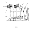
- FIG. 1 is a schematic diagram of a 3-D strip winding system for a special giant all-steel radial OTR tire according to one embodiment of the invention
- FIG. 2 is a front view of a pivoting device according to one embodiment of the invention as shown in FIG. 1 ;
- FIG. 3 is a partial enlargement of a pivoting device according to one embodiment of the invention as shown in FIG 2 ;
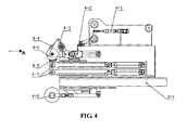
- FIG. 4 is a schematic diagram of a strip winding and applying device according to one embodiment of the invention.
- FIG. 5 is an "A" direction side view according to one embodiment of the invention as shown in FIG. 4 ;
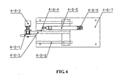
- FIG. 6 is a bottom view of a tachometer device according to one embodiment of the invention.
- FIG. 7 is a schematic diagram of a strip transportation bracket according to one embodiment of the invention.
- Cylinder bracket 4-8-5. Cylinder, 4-8-6. Cylinder hinged support, 4-8-7. Rail adapter, 4-8-8. Rails, 4-8-9. Slide blocks, 5 . Bracket, 5-1. Telescopic rod, 5-2. Servo drive roller for strip transportation, 5-3. Follow-up guide roller.
- a 3-D strip winding system for a special giant all-steel radial OTR tire comprises a movable base plate 1, a pivoting device 2, a support 3, a winding and applying device 4 and a bracket 5.
- the winding and applying device 4 is fixed on the support 3.
- the support 3 is flexibly connected to the pivoting device 2.
- the pivoting device 2 is rotatably connected to the movable base plate 1.
- the bracket 5 operates to minimize stretch of a rubber strip, whose output end is disposed on the support 3.
- the pivoting device 2 comprises a spin orbit of an external gear ring 2-1, a positioning and rotating inner race 2-2, a support plate 2-3, a servo motor 2-5 and drive gear 2-4.
- the spin orbit of an external gear ring 2-1 is fixed on the plane of the movable base plate 1.
- the positioning and rotating inner race 2-2 is flexibly attached inside the spin orbit of an external gear ring 2-1.
- One end of the support plate 2-3 is fixed to the positioning and rotating inner race 2-2.
- the drive servo motor 2-5 is rigidly disposed on the support plate 2-3, whose output end is connected to the drive gear 2-4 after passing through the support plate.
- the drive gear 2-4 is engaged with the outer edge of the spin orbit of an external gear ring 2-1.
- the winding and applying device 4 comprises: a floating guide 4-1, an applying and stitching roller 4-5, a drive unit for the applying and stitching roller cylinder 4-2, a support for the applying and stitching roller 4-3, a non-return device 4-4, a cutter 4-6, an air discharging roller 4-7, and a tachometer device 4-8. All above-mentioned units are installed on a supported plate of the support 3-1.
- the drive unit for the applying and stitching roller cylinder 4-2 is connected to a lower front portion of the floating guide 4-1.
- the support for the applying and stitching roller 4-3 is fixed at the front end of the drive unit for the applying and stitching roller cylinder 4-2.
- the support for the applying and stitching roller is substantially in a triangular shape.
- the non-return device 4-4 comprises a group of non-return rods, one end of which is a wedge shape, and the other end is flexibly connected to the upper end of the support for the applying and stitching roller 4-3.
- the wedge-shaped end falls down naturally through gravity against the applying and stitching roller 4-5, wherein the tip of the wedge shape touches the applying and stitching roller 4-5.
- the applying and stitching roller 4-5 is rotatably disposed at the bottom of the support for an applying and stitching roller 4-3.
- the cutter 4-6 is connected to the bottom of the applying and stitching roller 4-5.
- the air discharging roller 4-7 is disposed below the cutter 4-6.
- the tachometer device 4-8 is fixedly disposed below the air discharging roller 4-7.
- the tachometer device comprises: a tachometer roller 4-8-1, an encoder 4-8-2, a link 4-8-3, a cylinder bracket 4-8-4, a cylinder 4-8-5, a cylinder hinged support 4-8-6, rail adapters 4-8-7, rails 4-8-8 and slide blocks 4-8-9.
- the tachometer roller 4-8-1 is installed at front end of the link 4-8-3.
- the encoder 4-8-2 is fixed at side of the tachometer roller 4-8-1.
- the cylinder bracket 4-8-4 is fixedly connected to the link 4-8-3.
- the output end of the cylinder 4-8-5 is hinged with the cylinder bracket 4-8-4, and the input end of the cylinder 4-8-5 is flexibly connected to the hinged support 4-8-6.
- the rails 4-8-8 are placed rigidly below the rail adapter 4-8-7.
- the slide blocks 4-8-9 are disposed on a predetermined position of the rails 4-8-8 and are fastened to the link 4-8-3.
- the bracket comprises: a group of telescopic rod for bracket 5-1, a group of servo drive rollers for strip transportation 5-2, a group of follow-up guide rollers 5-3.
- the servo drive rollers for strip transportation 5-2 and the follow-up guide rollers 5-3 are installed at a proper position of telescopic rod 5-1 for bracket.
- the front end of the bracket 5 is connected to the support 3 and the back end to the movable base plate 1.
- the 3-D strip winding system for a special giant all-steel radial OTR tire of the invention operates as follows:
- the transversal and longitudinal adjusting unit on the movable base plate adjusts the transversal and longitudinal adjusting unit on the movable base plate to allow the winding and applying device to run in compliance with the tread profile. Then, adjust the pivoting device so as to meet the turning radian required between the sidewall and the crown.
- the rubber strip is fed onto the bracket by previous sequence, as per technical requirements.
- the strip has to be transported onto the winding and applying device after passing through the guide rollers on the bracket. By the help of the floating guide rollers, the strip is wound and applied, from applying and stitching roller, to the preset position of the green tire.
- the applying and stitching of the green tire is completed by the applying and stitching roller and the air discharging roller, which is used in conjunction with the movable base plate and the pivoting device to finish the winding and applying of the required shape for the green tire.
- the tachometer device can detect in real time the rotational speed of the green tire so that the rotational speed of the green tire can be adjusted to match that of strip transportation.
- the strip is cut by a cutter. Since the applied strip on the applying and stitching roller is also underneath the non-return device, it is possible to slightly insert a wedged-shape tip into the strip to push forward the strip; thus, the strip does not move back, which is convenient for next operation.
Landscapes
- Engineering & Computer Science (AREA)
- Mechanical Engineering (AREA)
- Tyre Moulding (AREA)
- Tires In General (AREA)
Applications Claiming Priority (1)
| Application Number | Priority Date | Filing Date | Title |
|---|---|---|---|
| CN2008100529895A CN101574853B (zh) | 2008-05-05 | 2008-05-05 | 一种特巨型全钢工程子午线轮胎三维缠贴机构 |
Publications (2)
| Publication Number | Publication Date |
|---|---|
| EP2116362A1 true EP2116362A1 (de) | 2009-11-11 |
| EP2116362B1 EP2116362B1 (de) | 2013-10-23 |
Family
ID=40912029
Family Applications (1)
| Application Number | Title | Priority Date | Filing Date |
|---|---|---|---|
| EP08016299.3A Ceased EP2116362B1 (de) | 2008-05-05 | 2008-09-16 | Dreidimensionales Streifenwickelsystem für einen speziellen riesigen Edelstahl-Radial-OTR-Reifen |
Country Status (3)
| Country | Link |
|---|---|
| US (1) | US20090272834A1 (de) |
| EP (1) | EP2116362B1 (de) |
| CN (1) | CN101574853B (de) |
Families Citing this family (5)
| Publication number | Priority date | Publication date | Assignee | Title |
|---|---|---|---|---|
| CN101951122B (zh) * | 2010-08-19 | 2012-07-04 | 常州大学 | 一种钢丝绳精密直线驱动装置 |
| CN108688208B (zh) * | 2018-05-24 | 2023-08-22 | 广州烨诺科技有限公司 | 一种轮胎缠压头结构 |
| CN112125041B (zh) * | 2020-10-22 | 2024-11-26 | 青岛众屹科锐工程技术有限公司 | 一种胶条均匀摆放及输送系统 |
| CN113640701B (zh) * | 2021-08-25 | 2022-08-23 | 深圳市裕富照明有限公司 | 一种用于led路灯的温度环境的测试设备 |
| CN114872331B (zh) * | 2022-07-08 | 2022-09-27 | 天津赛象科技股份有限公司 | 一种硅钢弹片与胶条自动化装配机构 |
Citations (8)
| Publication number | Priority date | Publication date | Assignee | Title |
|---|---|---|---|---|
| FR1426617A (fr) * | 1964-04-11 | 1966-01-28 | Continental Gummi Werke Ag | Machine pour la mise en place de couches en caoutchouc, ou matière synthétique analogue sur des corps notamment sur des pneumatiques ainsi que les corps tels pneumatiques conformes à ceux obtenus |
| US3549442A (en) * | 1967-07-26 | 1970-12-22 | American Mach & Foundry | Method of building a tire casing from a strip of rubber |
| US4222810A (en) * | 1977-04-05 | 1980-09-16 | Aktiebolaget Stabil Mekaniska Verkstad | Apparatus for applying a band of material to the side of a circular body of revolution |
| US4240863A (en) * | 1979-04-12 | 1980-12-23 | Caterpillar Tractor Co. | Control system for an elastomer extrusion and applicator apparatus |
| LU87565A1 (fr) * | 1988-07-28 | 1989-10-26 | Goodyear Tire & Rubber | Procede et appareil d'application de spires pour fabrication d'une bande de roulement |
| US5395475A (en) * | 1991-11-13 | 1995-03-07 | Bridgestone Corporation | Narrow belt-shaped member winding apparatus |
| EP1647394A1 (de) * | 2004-10-14 | 2006-04-19 | Sumitomo Rubber Industries Ltd. | Verfahren und Vorrichtung zur Herstellung eines Gegenstandes durch Wickeln eines Gummistreifens auf einen Tragkörper |
| EP1785263A1 (de) * | 2005-11-15 | 2007-05-16 | Sumtiomo Rubber Industries Ltd | Einrichtung zum Auflegen eines Gummibandes |
Family Cites Families (4)
| Publication number | Priority date | Publication date | Assignee | Title |
|---|---|---|---|---|
| US3843482A (en) * | 1972-05-03 | 1974-10-22 | Amf Inc | Tire tread winding machine having a mechanically programmed control system |
| US4596619A (en) * | 1982-05-17 | 1986-06-24 | Hercules Incorporated | Process for lining composite vessels |
| JP2714959B2 (ja) * | 1988-09-29 | 1998-02-16 | 横浜ゴム株式会社 | 粘着性リボン状材料の自動巻付け方法及び装置 |
| CN201208796Y (zh) * | 2008-05-05 | 2009-03-18 | 天津赛象科技股份有限公司 | 一种特巨型全钢工程子午线轮胎三维缠贴机构 |
-
2008
- 2008-05-05 CN CN2008100529895A patent/CN101574853B/zh active Active
- 2008-09-04 US US12/204,003 patent/US20090272834A1/en not_active Abandoned
- 2008-09-16 EP EP08016299.3A patent/EP2116362B1/de not_active Ceased
Patent Citations (8)
| Publication number | Priority date | Publication date | Assignee | Title |
|---|---|---|---|---|
| FR1426617A (fr) * | 1964-04-11 | 1966-01-28 | Continental Gummi Werke Ag | Machine pour la mise en place de couches en caoutchouc, ou matière synthétique analogue sur des corps notamment sur des pneumatiques ainsi que les corps tels pneumatiques conformes à ceux obtenus |
| US3549442A (en) * | 1967-07-26 | 1970-12-22 | American Mach & Foundry | Method of building a tire casing from a strip of rubber |
| US4222810A (en) * | 1977-04-05 | 1980-09-16 | Aktiebolaget Stabil Mekaniska Verkstad | Apparatus for applying a band of material to the side of a circular body of revolution |
| US4240863A (en) * | 1979-04-12 | 1980-12-23 | Caterpillar Tractor Co. | Control system for an elastomer extrusion and applicator apparatus |
| LU87565A1 (fr) * | 1988-07-28 | 1989-10-26 | Goodyear Tire & Rubber | Procede et appareil d'application de spires pour fabrication d'une bande de roulement |
| US5395475A (en) * | 1991-11-13 | 1995-03-07 | Bridgestone Corporation | Narrow belt-shaped member winding apparatus |
| EP1647394A1 (de) * | 2004-10-14 | 2006-04-19 | Sumitomo Rubber Industries Ltd. | Verfahren und Vorrichtung zur Herstellung eines Gegenstandes durch Wickeln eines Gummistreifens auf einen Tragkörper |
| EP1785263A1 (de) * | 2005-11-15 | 2007-05-16 | Sumtiomo Rubber Industries Ltd | Einrichtung zum Auflegen eines Gummibandes |
Also Published As
| Publication number | Publication date |
|---|---|
| US20090272834A1 (en) | 2009-11-05 |
| CN101574853A (zh) | 2009-11-11 |
| EP2116362B1 (de) | 2013-10-23 |
| CN101574853B (zh) | 2011-07-20 |
Similar Documents
| Publication | Publication Date | Title |
|---|---|---|
| EP2116362A1 (de) | Dreidimensionales Streifenwickelsystem für einen speziellen riesigen Edelstahl-Radial-OTR-Reifen | |
| CN103009651B (zh) | 一种高效率三鼓成型机 | |
| US9776366B2 (en) | Tool for positioning a strip for producing a tire blank | |
| CN101234534B (zh) | 带有切割机构的轮胎组装敷贴设备 | |
| CN203077629U (zh) | 一种高效率三鼓成型机 | |
| CN106862652A (zh) | 一种方管多角度锯切机 | |
| EP1785263A1 (de) | Einrichtung zum Auflegen eines Gummibandes | |
| US8245615B2 (en) | Tire tread skiving machine | |
| US11951703B2 (en) | Process and apparatus for building tyres for vehicle wheels | |
| CN101229691B (zh) | 带有切割机构的轮胎组装敷贴设备 | |
| ITPI20110084A1 (it) | Apparecchiatura per tagliare trasversalmente corpi tubolari | |
| EP2799219A1 (de) | Bandschichten-zufuhrrahmen und zufuhrverfahren dafür | |
| CN203901751U (zh) | 一种轮胎帘布裁纱机裁断装置 | |
| CN104495345B (zh) | 提交出口移行机 | |
| CN207578501U (zh) | 一种绝缘纸管加工用切管机 | |
| CN219900033U (zh) | 矫直切断设备 | |
| CN104028830B (zh) | 一种管件切割系统 | |
| CN118893756B (zh) | 一种可回收废料的橡胶圈修边机 | |
| CN105082233B (zh) | 一种自动剪管机 | |
| CN212193338U (zh) | 一种切条装置 | |
| CN104925574B (zh) | 一种原纸分切机的夹紧装置 | |
| CN203806777U (zh) | 一种接近收卷双边单独调压系统 | |
| CN209599273U (zh) | 橡胶传动带切割成型机 | |
| CN206633243U (zh) | 硅钙板毛边切割机 | |
| CN102059599B (zh) | 多段轮廓面轮胎再制造打磨装置 |
Legal Events
| Date | Code | Title | Description |
|---|---|---|---|
| PUAI | Public reference made under article 153(3) epc to a published international application that has entered the european phase |
Free format text: ORIGINAL CODE: 0009012 |
|
| AK | Designated contracting states |
Kind code of ref document: A1 Designated state(s): AT BE BG CH CY CZ DE DK EE ES FI FR GB GR HR HU IE IS IT LI LT LU LV MC MT NL NO PL PT RO SE SI SK TR |
|
| AX | Request for extension of the european patent |
Extension state: AL BA MK RS |
|
| 17P | Request for examination filed |
Effective date: 20100430 |
|
| AKX | Designation fees paid |
Designated state(s): AT BE BG CH CY CZ DE DK EE ES FI FR GB GR HR HU IE IS IT LI LT LU LV MC MT NL NO PL PT RO SE SI SK TR |
|
| 17Q | First examination report despatched |
Effective date: 20110606 |
|
| GRAP | Despatch of communication of intention to grant a patent |
Free format text: ORIGINAL CODE: EPIDOSNIGR1 |
|
| INTG | Intention to grant announced |
Effective date: 20130507 |
|
| GRAS | Grant fee paid |
Free format text: ORIGINAL CODE: EPIDOSNIGR3 |
|
| GRAA | (expected) grant |
Free format text: ORIGINAL CODE: 0009210 |
|
| RIN1 | Information on inventor provided before grant (corrected) |
Inventor name: ZHANG, ZHIQUAN Inventor name: ZHANG, JIANHAO |
|
| AK | Designated contracting states |
Kind code of ref document: B1 Designated state(s): AT BE BG CH CY CZ DE DK EE ES FI FR GB GR HR HU IE IS IT LI LT LU LV MC MT NL NO PL PT RO SE SI SK TR |
|
| REG | Reference to a national code |
Ref country code: GB Ref legal event code: FG4D |
|
| REG | Reference to a national code |
Ref country code: CH Ref legal event code: EP |
|
| REG | Reference to a national code |
Ref country code: AT Ref legal event code: REF Ref document number: 637300 Country of ref document: AT Kind code of ref document: T Effective date: 20131115 |
|
| REG | Reference to a national code |
Ref country code: IE Ref legal event code: FG4D |
|
| REG | Reference to a national code |
Ref country code: RO Ref legal event code: EPE |
|
| REG | Reference to a national code |
Ref country code: DE Ref legal event code: R096 Ref document number: 602008028232 Country of ref document: DE Effective date: 20131219 |
|
| REG | Reference to a national code |
Ref country code: NL Ref legal event code: VDEP Effective date: 20131023 |
|
| REG | Reference to a national code |
Ref country code: AT Ref legal event code: MK05 Ref document number: 637300 Country of ref document: AT Kind code of ref document: T Effective date: 20131023 |
|
| REG | Reference to a national code |
Ref country code: LT Ref legal event code: MG4D |
|
| PG25 | Lapsed in a contracting state [announced via postgrant information from national office to epo] |
Ref country code: IS Free format text: LAPSE BECAUSE OF FAILURE TO SUBMIT A TRANSLATION OF THE DESCRIPTION OR TO PAY THE FEE WITHIN THE PRESCRIBED TIME-LIMIT Effective date: 20140223 Ref country code: NO Free format text: LAPSE BECAUSE OF FAILURE TO SUBMIT A TRANSLATION OF THE DESCRIPTION OR TO PAY THE FEE WITHIN THE PRESCRIBED TIME-LIMIT Effective date: 20140123 Ref country code: SE Free format text: LAPSE BECAUSE OF FAILURE TO SUBMIT A TRANSLATION OF THE DESCRIPTION OR TO PAY THE FEE WITHIN THE PRESCRIBED TIME-LIMIT Effective date: 20131023 Ref country code: HR Free format text: LAPSE BECAUSE OF FAILURE TO SUBMIT A TRANSLATION OF THE DESCRIPTION OR TO PAY THE FEE WITHIN THE PRESCRIBED TIME-LIMIT Effective date: 20131023 Ref country code: LT Free format text: LAPSE BECAUSE OF FAILURE TO SUBMIT A TRANSLATION OF THE DESCRIPTION OR TO PAY THE FEE WITHIN THE PRESCRIBED TIME-LIMIT Effective date: 20131023 Ref country code: FI Free format text: LAPSE BECAUSE OF FAILURE TO SUBMIT A TRANSLATION OF THE DESCRIPTION OR TO PAY THE FEE WITHIN THE PRESCRIBED TIME-LIMIT Effective date: 20131023 Ref country code: BE Free format text: LAPSE BECAUSE OF FAILURE TO SUBMIT A TRANSLATION OF THE DESCRIPTION OR TO PAY THE FEE WITHIN THE PRESCRIBED TIME-LIMIT Effective date: 20131023 Ref country code: NL Free format text: LAPSE BECAUSE OF FAILURE TO SUBMIT A TRANSLATION OF THE DESCRIPTION OR TO PAY THE FEE WITHIN THE PRESCRIBED TIME-LIMIT Effective date: 20131023 |
|
| PG25 | Lapsed in a contracting state [announced via postgrant information from national office to epo] |
Ref country code: ES Free format text: LAPSE BECAUSE OF FAILURE TO SUBMIT A TRANSLATION OF THE DESCRIPTION OR TO PAY THE FEE WITHIN THE PRESCRIBED TIME-LIMIT Effective date: 20131023 Ref country code: LV Free format text: LAPSE BECAUSE OF FAILURE TO SUBMIT A TRANSLATION OF THE DESCRIPTION OR TO PAY THE FEE WITHIN THE PRESCRIBED TIME-LIMIT Effective date: 20131023 Ref country code: AT Free format text: LAPSE BECAUSE OF FAILURE TO SUBMIT A TRANSLATION OF THE DESCRIPTION OR TO PAY THE FEE WITHIN THE PRESCRIBED TIME-LIMIT Effective date: 20131023 Ref country code: CY Free format text: LAPSE BECAUSE OF FAILURE TO SUBMIT A TRANSLATION OF THE DESCRIPTION OR TO PAY THE FEE WITHIN THE PRESCRIBED TIME-LIMIT Effective date: 20131023 |
|
| PG25 | Lapsed in a contracting state [announced via postgrant information from national office to epo] |
Ref country code: PT Free format text: LAPSE BECAUSE OF FAILURE TO SUBMIT A TRANSLATION OF THE DESCRIPTION OR TO PAY THE FEE WITHIN THE PRESCRIBED TIME-LIMIT Effective date: 20140224 |
|
| REG | Reference to a national code |
Ref country code: DE Ref legal event code: R097 Ref document number: 602008028232 Country of ref document: DE |
|
| PG25 | Lapsed in a contracting state [announced via postgrant information from national office to epo] |
Ref country code: EE Free format text: LAPSE BECAUSE OF FAILURE TO SUBMIT A TRANSLATION OF THE DESCRIPTION OR TO PAY THE FEE WITHIN THE PRESCRIBED TIME-LIMIT Effective date: 20131023 |
|
| PG25 | Lapsed in a contracting state [announced via postgrant information from national office to epo] |
Ref country code: SK Free format text: LAPSE BECAUSE OF FAILURE TO SUBMIT A TRANSLATION OF THE DESCRIPTION OR TO PAY THE FEE WITHIN THE PRESCRIBED TIME-LIMIT Effective date: 20131023 Ref country code: PL Free format text: LAPSE BECAUSE OF FAILURE TO SUBMIT A TRANSLATION OF THE DESCRIPTION OR TO PAY THE FEE WITHIN THE PRESCRIBED TIME-LIMIT Effective date: 20131023 |
|
| PLBE | No opposition filed within time limit |
Free format text: ORIGINAL CODE: 0009261 |
|
| STAA | Information on the status of an ep patent application or granted ep patent |
Free format text: STATUS: NO OPPOSITION FILED WITHIN TIME LIMIT |
|
| PG25 | Lapsed in a contracting state [announced via postgrant information from national office to epo] |
Ref country code: DK Free format text: LAPSE BECAUSE OF FAILURE TO SUBMIT A TRANSLATION OF THE DESCRIPTION OR TO PAY THE FEE WITHIN THE PRESCRIBED TIME-LIMIT Effective date: 20131023 |
|
| 26N | No opposition filed |
Effective date: 20140724 |
|
| REG | Reference to a national code |
Ref country code: DE Ref legal event code: R097 Ref document number: 602008028232 Country of ref document: DE Effective date: 20140724 |
|
| PG25 | Lapsed in a contracting state [announced via postgrant information from national office to epo] |
Ref country code: SI Free format text: LAPSE BECAUSE OF FAILURE TO SUBMIT A TRANSLATION OF THE DESCRIPTION OR TO PAY THE FEE WITHIN THE PRESCRIBED TIME-LIMIT Effective date: 20131023 |
|
| PG25 | Lapsed in a contracting state [announced via postgrant information from national office to epo] |
Ref country code: MC Free format text: LAPSE BECAUSE OF FAILURE TO SUBMIT A TRANSLATION OF THE DESCRIPTION OR TO PAY THE FEE WITHIN THE PRESCRIBED TIME-LIMIT Effective date: 20131023 Ref country code: LU Free format text: LAPSE BECAUSE OF FAILURE TO SUBMIT A TRANSLATION OF THE DESCRIPTION OR TO PAY THE FEE WITHIN THE PRESCRIBED TIME-LIMIT Effective date: 20140916 |
|
| REG | Reference to a national code |
Ref country code: CH Ref legal event code: PL |
|
| GBPC | Gb: european patent ceased through non-payment of renewal fee |
Effective date: 20140916 |
|
| PG25 | Lapsed in a contracting state [announced via postgrant information from national office to epo] |
Ref country code: LI Free format text: LAPSE BECAUSE OF NON-PAYMENT OF DUE FEES Effective date: 20140930 Ref country code: GB Free format text: LAPSE BECAUSE OF NON-PAYMENT OF DUE FEES Effective date: 20140916 Ref country code: CH Free format text: LAPSE BECAUSE OF NON-PAYMENT OF DUE FEES Effective date: 20140930 |
|
| PG25 | Lapsed in a contracting state [announced via postgrant information from national office to epo] |
Ref country code: IE Free format text: LAPSE BECAUSE OF NON-PAYMENT OF DUE FEES Effective date: 20140916 |
|
| PG25 | Lapsed in a contracting state [announced via postgrant information from national office to epo] |
Ref country code: BG Free format text: LAPSE BECAUSE OF FAILURE TO SUBMIT A TRANSLATION OF THE DESCRIPTION OR TO PAY THE FEE WITHIN THE PRESCRIBED TIME-LIMIT Effective date: 20131023 |
|
| PG25 | Lapsed in a contracting state [announced via postgrant information from national office to epo] |
Ref country code: GR Free format text: LAPSE BECAUSE OF FAILURE TO SUBMIT A TRANSLATION OF THE DESCRIPTION OR TO PAY THE FEE WITHIN THE PRESCRIBED TIME-LIMIT Effective date: 20140124 Ref country code: MT Free format text: LAPSE BECAUSE OF FAILURE TO SUBMIT A TRANSLATION OF THE DESCRIPTION OR TO PAY THE FEE WITHIN THE PRESCRIBED TIME-LIMIT Effective date: 20131023 |
|
| PG25 | Lapsed in a contracting state [announced via postgrant information from national office to epo] |
Ref country code: HU Free format text: LAPSE BECAUSE OF FAILURE TO SUBMIT A TRANSLATION OF THE DESCRIPTION OR TO PAY THE FEE WITHIN THE PRESCRIBED TIME-LIMIT; INVALID AB INITIO Effective date: 20080916 |
|
| REG | Reference to a national code |
Ref country code: FR Ref legal event code: PLFP Year of fee payment: 9 |
|
| REG | Reference to a national code |
Ref country code: FR Ref legal event code: PLFP Year of fee payment: 10 |
|
| REG | Reference to a national code |
Ref country code: FR Ref legal event code: PLFP Year of fee payment: 11 |
|
| PGFP | Annual fee paid to national office [announced via postgrant information from national office to epo] |
Ref country code: TR Payment date: 20190913 Year of fee payment: 12 Ref country code: RO Payment date: 20190912 Year of fee payment: 12 Ref country code: FR Payment date: 20190923 Year of fee payment: 12 Ref country code: IT Payment date: 20190920 Year of fee payment: 12 Ref country code: CZ Payment date: 20190903 Year of fee payment: 12 |
|
| PG25 | Lapsed in a contracting state [announced via postgrant information from national office to epo] |
Ref country code: RO Free format text: LAPSE BECAUSE OF NON-PAYMENT OF DUE FEES Effective date: 20200916 Ref country code: CZ Free format text: LAPSE BECAUSE OF NON-PAYMENT OF DUE FEES Effective date: 20200916 |
|
| PG25 | Lapsed in a contracting state [announced via postgrant information from national office to epo] |
Ref country code: FR Free format text: LAPSE BECAUSE OF NON-PAYMENT OF DUE FEES Effective date: 20200930 |
|
| PG25 | Lapsed in a contracting state [announced via postgrant information from national office to epo] |
Ref country code: IT Free format text: LAPSE BECAUSE OF NON-PAYMENT OF DUE FEES Effective date: 20200916 |
|
| PGFP | Annual fee paid to national office [announced via postgrant information from national office to epo] |
Ref country code: DE Payment date: 20210921 Year of fee payment: 14 |
|
| REG | Reference to a national code |
Ref country code: DE Ref legal event code: R119 Ref document number: 602008028232 Country of ref document: DE |
|
| PG25 | Lapsed in a contracting state [announced via postgrant information from national office to epo] |
Ref country code: DE Free format text: LAPSE BECAUSE OF NON-PAYMENT OF DUE FEES Effective date: 20230401 |
|
| PG25 | Lapsed in a contracting state [announced via postgrant information from national office to epo] |
Ref country code: TR Free format text: LAPSE BECAUSE OF NON-PAYMENT OF DUE FEES Effective date: 20200916 |