EP2116403A1 - Dispositif de suspension et d'amortissement pour véhicules motorisés - Google Patents
Dispositif de suspension et d'amortissement pour véhicules motorisés Download PDFInfo
- Publication number
- EP2116403A1 EP2116403A1 EP09169057A EP09169057A EP2116403A1 EP 2116403 A1 EP2116403 A1 EP 2116403A1 EP 09169057 A EP09169057 A EP 09169057A EP 09169057 A EP09169057 A EP 09169057A EP 2116403 A1 EP2116403 A1 EP 2116403A1
- Authority
- EP
- European Patent Office
- Prior art keywords
- spring
- medium
- suspension
- damping
- cylinder
- Prior art date
- Legal status (The legal status is an assumption and is not a legal conclusion. Google has not performed a legal analysis and makes no representation as to the accuracy of the status listed.)
- Granted
Links
- 238000013016 damping Methods 0.000 title claims abstract description 75
- 239000000725 suspension Substances 0.000 title claims abstract description 39
- 238000007906 compression Methods 0.000 claims description 9
- 230000006835 compression Effects 0.000 claims description 9
- 230000003068 static effect Effects 0.000 claims description 3
- 238000007599 discharging Methods 0.000 claims description 2
- 230000005484 gravity Effects 0.000 claims description 2
- 239000007788 liquid Substances 0.000 claims description 2
- 239000012530 fluid Substances 0.000 abstract description 4
- 238000001816 cooling Methods 0.000 description 9
- 230000000694 effects Effects 0.000 description 3
- 238000010438 heat treatment Methods 0.000 description 3
- IJGRMHOSHXDMSA-UHFFFAOYSA-N Atomic nitrogen Chemical compound N#N IJGRMHOSHXDMSA-UHFFFAOYSA-N 0.000 description 2
- 230000004323 axial length Effects 0.000 description 2
- 230000001419 dependent effect Effects 0.000 description 2
- 238000010586 diagram Methods 0.000 description 1
- 238000009472 formulation Methods 0.000 description 1
- 239000010720 hydraulic oil Substances 0.000 description 1
- 238000009434 installation Methods 0.000 description 1
- 239000000203 mixture Substances 0.000 description 1
- 229910052757 nitrogen Inorganic materials 0.000 description 1
- 238000005192 partition Methods 0.000 description 1
- 235000011837 pasties Nutrition 0.000 description 1
- 238000007789 sealing Methods 0.000 description 1
- 238000010792 warming Methods 0.000 description 1
Images



Classifications
-
- B—PERFORMING OPERATIONS; TRANSPORTING
- B60—VEHICLES IN GENERAL
- B60G—VEHICLE SUSPENSION ARRANGEMENTS
- B60G17/00—Resilient suspensions having means for adjusting the spring or vibration-damper characteristics, for regulating the distance between a supporting surface and a sprung part of vehicle or for locking suspension during use to meet varying vehicular or surface conditions, e.g. due to speed or load
- B60G17/02—Spring characteristics, e.g. mechanical springs and mechanical adjusting means
- B60G17/04—Spring characteristics, e.g. mechanical springs and mechanical adjusting means fluid spring characteristics
-
- B—PERFORMING OPERATIONS; TRANSPORTING
- B60—VEHICLES IN GENERAL
- B60G—VEHICLE SUSPENSION ARRANGEMENTS
- B60G15/00—Resilient suspensions characterised by arrangement, location or type of combined spring and vibration damper, e.g. telescopic type
- B60G15/08—Resilient suspensions characterised by arrangement, location or type of combined spring and vibration damper, e.g. telescopic type having fluid spring
- B60G15/12—Resilient suspensions characterised by arrangement, location or type of combined spring and vibration damper, e.g. telescopic type having fluid spring and fluid damper
-
- F—MECHANICAL ENGINEERING; LIGHTING; HEATING; WEAPONS; BLASTING
- F16—ENGINEERING ELEMENTS AND UNITS; GENERAL MEASURES FOR PRODUCING AND MAINTAINING EFFECTIVE FUNCTIONING OF MACHINES OR INSTALLATIONS; THERMAL INSULATION IN GENERAL
- F16F—SPRINGS; SHOCK-ABSORBERS; MEANS FOR DAMPING VIBRATION
- F16F9/00—Springs, vibration-dampers, shock-absorbers, or similarly-constructed movement-dampers using a fluid or the equivalent as damping medium
- F16F9/06—Springs, vibration-dampers, shock-absorbers, or similarly-constructed movement-dampers using a fluid or the equivalent as damping medium using both gas and liquid
- F16F9/066—Units characterised by the partition, baffle or like element
-
- F—MECHANICAL ENGINEERING; LIGHTING; HEATING; WEAPONS; BLASTING
- F16—ENGINEERING ELEMENTS AND UNITS; GENERAL MEASURES FOR PRODUCING AND MAINTAINING EFFECTIVE FUNCTIONING OF MACHINES OR INSTALLATIONS; THERMAL INSULATION IN GENERAL
- F16F—SPRINGS; SHOCK-ABSORBERS; MEANS FOR DAMPING VIBRATION
- F16F9/00—Springs, vibration-dampers, shock-absorbers, or similarly-constructed movement-dampers using a fluid or the equivalent as damping medium
- F16F9/06—Springs, vibration-dampers, shock-absorbers, or similarly-constructed movement-dampers using a fluid or the equivalent as damping medium using both gas and liquid
- F16F9/08—Springs, vibration-dampers, shock-absorbers, or similarly-constructed movement-dampers using a fluid or the equivalent as damping medium using both gas and liquid where gas is in a chamber with a flexible wall
- F16F9/096—Springs, vibration-dampers, shock-absorbers, or similarly-constructed movement-dampers using a fluid or the equivalent as damping medium using both gas and liquid where gas is in a chamber with a flexible wall comprising a hydropneumatic accumulator of the membrane type provided on the upper or the lower end of a damper or separately from or laterally on the damper
-
- F—MECHANICAL ENGINEERING; LIGHTING; HEATING; WEAPONS; BLASTING
- F16—ENGINEERING ELEMENTS AND UNITS; GENERAL MEASURES FOR PRODUCING AND MAINTAINING EFFECTIVE FUNCTIONING OF MACHINES OR INSTALLATIONS; THERMAL INSULATION IN GENERAL
- F16F—SPRINGS; SHOCK-ABSORBERS; MEANS FOR DAMPING VIBRATION
- F16F9/00—Springs, vibration-dampers, shock-absorbers, or similarly-constructed movement-dampers using a fluid or the equivalent as damping medium
- F16F9/30—Springs, vibration-dampers, shock-absorbers, or similarly-constructed movement-dampers using a fluid or the equivalent as damping medium with solid or semi-solid material, e.g. pasty masses, as damping medium
- F16F9/303—Springs, vibration-dampers, shock-absorbers, or similarly-constructed movement-dampers using a fluid or the equivalent as damping medium with solid or semi-solid material, e.g. pasty masses, as damping medium the damper being of the telescopic type
-
- F—MECHANICAL ENGINEERING; LIGHTING; HEATING; WEAPONS; BLASTING
- F16—ENGINEERING ELEMENTS AND UNITS; GENERAL MEASURES FOR PRODUCING AND MAINTAINING EFFECTIVE FUNCTIONING OF MACHINES OR INSTALLATIONS; THERMAL INSULATION IN GENERAL
- F16F—SPRINGS; SHOCK-ABSORBERS; MEANS FOR DAMPING VIBRATION
- F16F9/00—Springs, vibration-dampers, shock-absorbers, or similarly-constructed movement-dampers using a fluid or the equivalent as damping medium
- F16F9/32—Details
- F16F9/48—Arrangements for providing different damping effects at different parts of the stroke
-
- B—PERFORMING OPERATIONS; TRANSPORTING
- B60—VEHICLES IN GENERAL
- B60G—VEHICLE SUSPENSION ARRANGEMENTS
- B60G2500/00—Indexing codes relating to the regulated action or device
- B60G2500/30—Height or ground clearance
- B60G2500/302—Height or ground clearance using distributor valves
Definitions
- the present invention relates to a suspension and damping device for load-bearing and resilient wheel support and for damping suspension movements in a motor vehicle, comprising at least one spring cylinder with a relatively movable in a cylinder piston, which is used to generate a load-bearing suspension spring force against an elastically compressible spring medium acts, wherein for damping a separate, independent of the spring medium circuit of a hydraulic damping medium is provided.
- a damping device has a separate, independent of the spring cylinder and the spring medium circuit of a hydraulic damping medium.
- a damping device has a separate, independent of the spring cylinder and the spring medium circuit of a hydraulic damping medium.
- at least one separate damping cylinder with a relatively movable in a cylinder damper piston and at least one hydraulically connected to the damper cylinder damping valve is required.
- the piston of the spring cylinder is driven via a drive device formed by a gear mechanism, which converts the pivoting movements of a wheel Schwingungskarmarms in the linear relative movements between the cylinder and the piston of the spring cylinder.
- the damping device should cooperate with the same drive means as well as the spring cylinder, but the media (spring and damping medium) are completely separated from each other.
- the background is that there is no thermal dependency, as a result of which damping-induced heating of the damping medium is uncritical insofar as the temperature of the spring medium and thus also the pressure and the pressure-dependent suspension spring force remain unaffected. In contrast, a warming of the spring medium would also cause a change in the pressure and thus the suspension spring force.
- the known suspension and damping device has However, a relatively complex structure, which is also noticeable by a relatively large installation volume and weight.
- the present invention has for its object to provide a suspension and damping device of the generic type described above, which is characterized by optimal suspension and damping properties in a particularly compact and lightweight design.
- the invention provides that the piston within the cylinder two working spaces separated from each other, wherein the first working space associated with the spring medium and the second working space of the damping medium.
- the spring cylinder according to the invention is thus basically a kind of strut in the conventional sense, but with a hydraulic damping circuit is separated from the spring medium via the piston.
- the second working space is connected via a damping valve arrangement hydraulically connected to a hydraulic tank, in which the damping medium is under a certain biasing pressure of for example 3 to 5 bar.
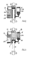
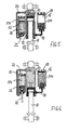
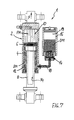
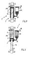
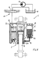
- a suspension and damping device 1 consists in all embodiments of (at least) a spring cylinder 2, the direct arrangement between a vehicle or a wheel Schwingingarm and a vehicle frame (both not shown) is provided.
- the spring cylinder 2 consists telescopically of a cylinder 4 and a linearly displaceably guided therein piston 6 with a piston rod 8 which is circumferentially sealed out of the cylinder 4 led out.
- the piston 6 abuts against the inner surface of the cylinder 4 via at least one annular piston seal.
- the piston 6 separates two working spaces from one another within the cylinder 4, wherein a first working space 10 is assigned to the spring medium FM and a second working space 12 to the damping medium DM. Consequently, according to the invention, the piston 6 also separates a "spring circuit" from a "damping circuit".
- the spring cylinder 2 is designed as a pressure cylinder. This means that it acts practically as a compression spring to support the respective load.
- the spring medium FM associated first working space 10 is formed as a cylindrical space on the piston rod 8 opposite side of the piston 6. Since the second working space 12 according to the invention is associated with the damping medium DM, in this embodiment the piston rod 8 advantageously acts as a cooling element for cooling the damping medium DM which heats up during damping or throttling.
- the second working chamber 12 is connected via a damping valve assembly 14 with a hydraulic reservoir 16.
- the damping valve assembly 14 is arranged integrated in an inlet region of the hydraulic tank 16.
- the hydraulic tank 16 is preferably arranged as a separate component externally, separated from the spring cylinder 2 and connected via a line 18 to the second working chamber 12 of the spring cylinder 2.
- the damping valve assembly 14 is arranged integrated in the inlet region of the hydraulic tank 16, creates a damping or throttle-induced heating of the damping medium DM advantageously in a remote from the spring cylinder 2 and thus also away from the spring medium FM area.
- an additional cooling effect for cooling the damping medium DM is advantageously achieved by the external hydraulic tank 16 by heat over a large outer surface (cooling surface) is discharged to the environment.
- a heat share on the damping medium DM also get into the second working space 12, however, acts, as already indicated above, the piston rod 8 as a cooling element by being surrounded by the damping medium DM and thereby transported its heat to the outside. This is particularly effective, because the piston rod in the suspension movements yes sometimes also moves outward from the cylinder 4 and can deliver any heat there to the environment. It can be said that the piston rod 8 forms a kind of "heat pump".
- heat is also released via the outer surface of the cylinder 4 to the environment.
- a damping takes place only in half suspension cycle, by a corresponding design of the damping valve assembly 14 (with throttle and check valves) only during rebound, while compression movements are almost undamped, so that heat actually only at Rebounding occurs.
- the compression stroke can be used for cooling.
- the hydraulic tank 16 is preferably arranged in a vehicle so that it is arranged approximately parallel to the spring cylinder 2, in such a way that the damping medium DM is due to gravity in the lower region.
- a space 19 above the damping medium DM air can be arranged. According to the invention, this space 19 above the damping medium DM under a certain biasing pressure of z. B. 3 to 5 bar to assist in the compression of the flow in the second working space inside (to accelerate).
- the first working space 10 is connected via a line 20 to a spring accumulator 22 containing the elastically compressible spring medium FM.
- This spring accumulator 22 is preferably designed as a hydropneumatic piston accumulator with a floating in a storage cylinder 24 (floating) separating piston 26.
- the separating piston 26 abuts sealingly against the inner surface of the storage cylinder 24 via at least one sealing ring and thereby separates a storage space 28 connected hydraulically via the line 20 with the first working space 10 from a spring chamber 30 containing the spring medium FM, the first working space 10 and the storage space 28 are completely filled in this case with a hydraulic medium HM.
- the piston 6 of the spring cylinder 2 acts indirectly via the hydraulic medium HM and the separating piston 26 against the spring medium FM within the spring chamber 30th
- the separating piston 26 is arranged as a partition completely within the storage cylinder 24. As a result, it must have a relatively large axial length in order to avoid that it tilts within the storage cylinder 24 and thereby jams (so-called "drawer effect").
- the separating piston 26 has a separating piston rod 32 which extends axially through the storage space 28 and is sealed out of the storage cylinder 24.
- an additional guidance of the separating piston 26 against tilting is achieved by the separating piston rod 32, so that the separating piston 26 itself can be designed with a shorter axial length.
- overall length of the spring accumulator 22 can be saved.
- the spring accumulator 22 acts in this embodiment due to the separating piston rod 32 as a pressure transducer such that the pressure of the spring medium FM is always smaller than the pressure of the hydraulic medium HM. This is because they are each pressurized opposite surfaces of the separating piston 26 are different in size.
- the spring accumulator 22 is preferably arranged in parallel next to the spring cylinder 2, in particular in an orientation in which the piston rod 8 of the spring cylinder 2 and the separating piston rod 32 of the spring accumulator 22, each with the same direction of movement in the same direction.
- the separating piston rod 32 moves out of the spring accumulator 22, although the spring cylinder 2 rebounds, ie when the piston rod 8 also moves out of the cylinder 4. This avoids collision problems with other vehicle components in the vehicle suspension movements.
- the first working chamber 10 of the spring cylinder 2 is filled directly with the elastically compressible spring medium FM, so that the piston 6 acts directly against the spring medium FM.
- an external auxiliary reservoir 36 may be connected via a line 38 to the first working space 10.
- the elastic spring medium FM is disposed directly in the first working space 10.
- a compressible spring medium FM in particular a gaseous medium can be used, for example nitrogen.
- a gaseous medium for example nitrogen.
- any other, for example, liquid or pasty (highly viscous) medium is suitable.
- Damping medium DM and / or hydraulic medium HM a conventional, especially low-viscosity hydraulic oil can be used.
- the spring cylinder 2 is preferably equipped with a device for hydraulic cushioning.
- This cushioning is in Fig. 1 and 4 each designated by the reference numeral 40.
- This cushioning 40 preferably acts in the compression direction such that a deceleration of the suspension movements is ensured in each case towards the end of Einfederungshubes before reaching a mechanical end stop.
- it is a path-dependent hydraulic throttle device with a plunger 42 which can be displaced telescopically into the piston 6 and which has an axial flow channel into which open a plurality of radial transverse openings distributed over the length. By immersing the plunger 42 in the piston 6, the transverse openings are successively closed successively when moving up to the end stop position.
- a hydraulic leveling device 44 which is designed such that a static vehicle level is variable by supplying or discharging hydraulic medium HM in or out of the spring circuit.
- the leveling device 44 consists of a switching valve 46, a tank 48 and a pump 50.
- the switching valve 46 is designed as a 3/3-way valve and closed in the illustrated position. In a first switching position, the pump 50 can be connected to the suspension circuit to supply hydraulic medium and thereby raise the level. In a second switching position, the suspension circuit is connected to the tank 48 to drain hydraulic fluid to the level reduction.
- the invention is not limited to the illustrated and described embodiments, but also includes all the same in the context of the invention embodiments. Furthermore, the invention has not yet been limited to the feature combination defined in claim 1, but may also be any be defined as a different combination of certain features of all the individual features disclosed overall. This means that in principle virtually every individual feature of claim 1 can be omitted or replaced by at least one individual feature disclosed elsewhere in the application. In this respect, the claim 1 is to be understood only as a first formulation attempt for an invention.
Landscapes
- Engineering & Computer Science (AREA)
- General Engineering & Computer Science (AREA)
- Mechanical Engineering (AREA)
- Vehicle Body Suspensions (AREA)
- Fluid-Damping Devices (AREA)
- Vibration Prevention Devices (AREA)
Applications Claiming Priority (2)
| Application Number | Priority Date | Filing Date | Title |
|---|---|---|---|
| DE202004005623U DE202004005623U1 (de) | 2004-04-08 | 2004-04-08 | Federungs- und Dämpfungseinrichtung für Kraftfahrzeuge |
| EP05102596A EP1584502B1 (fr) | 2004-04-08 | 2005-04-01 | Dispositif de suspension et d'amortissement pour véhicules motorisés |
Related Parent Applications (2)
| Application Number | Title | Priority Date | Filing Date |
|---|---|---|---|
| EP05102596.3 Division | 2005-04-01 | ||
| EP05102596A Division EP1584502B1 (fr) | 2004-04-08 | 2005-04-01 | Dispositif de suspension et d'amortissement pour véhicules motorisés |
Publications (2)
| Publication Number | Publication Date |
|---|---|
| EP2116403A1 true EP2116403A1 (fr) | 2009-11-11 |
| EP2116403B1 EP2116403B1 (fr) | 2012-01-18 |
Family
ID=34854257
Family Applications (2)
| Application Number | Title | Priority Date | Filing Date |
|---|---|---|---|
| EP09169057A Expired - Lifetime EP2116403B1 (fr) | 2004-04-08 | 2005-04-01 | Dispositif de suspension et d'amortissement pour véhicules motorisés |
| EP05102596A Expired - Lifetime EP1584502B1 (fr) | 2004-04-08 | 2005-04-01 | Dispositif de suspension et d'amortissement pour véhicules motorisés |
Family Applications After (1)
| Application Number | Title | Priority Date | Filing Date |
|---|---|---|---|
| EP05102596A Expired - Lifetime EP1584502B1 (fr) | 2004-04-08 | 2005-04-01 | Dispositif de suspension et d'amortissement pour véhicules motorisés |
Country Status (4)
| Country | Link |
|---|---|
| EP (2) | EP2116403B1 (fr) |
| AT (2) | ATE541727T1 (fr) |
| DE (2) | DE202004005623U1 (fr) |
| ES (1) | ES2332370T3 (fr) |
Families Citing this family (6)
| Publication number | Priority date | Publication date | Assignee | Title |
|---|---|---|---|---|
| EP2527171A1 (fr) | 2008-11-18 | 2012-11-28 | Hemscheidt Fahrwerktechnik GmbH & Co. KG | Système d'amortissement pour véhicules |
| ATE555929T1 (de) | 2008-12-12 | 2012-05-15 | Hemscheidt Fahrwerktech Gmbh | Dämpfungseinrichtung für fahrzeuge |
| DE202008018221U1 (de) | 2008-12-12 | 2012-02-27 | Hemscheidt Fahrwerktechnik Gmbh & Co. Kg | Dämpfungseinrichtung für Fahrzeuge |
| ATE550569T1 (de) | 2009-08-19 | 2012-04-15 | Hemscheidt Fahrwerktech Gmbh | Hydropneumatischer kolbenspeicher |
| CN109268428B (zh) * | 2018-11-02 | 2020-05-26 | 常州大学 | 一种基于非线性刚度对称隔振的流体隔振器 |
| CN119773430B (zh) * | 2024-12-27 | 2025-11-25 | 渤赛动力科技(无锡)有限公司 | 一种全地形车可自动调节的悬挂系统 |
Citations (8)
| Publication number | Priority date | Publication date | Assignee | Title |
|---|---|---|---|---|
| US3677141A (en) * | 1969-11-07 | 1972-07-18 | Monsun Tison Ab | Device in fluid-containing cylinders having a fluid-operated piston |
| JPS6264603A (ja) * | 1985-09-15 | 1987-03-23 | Showa Seisakusho:Kk | 車輪懸架装置用油圧緩衝器における底突き防止装置 |
| DE3902743C1 (en) | 1989-01-31 | 1990-07-26 | Daimler-Benz Aktiengesellschaft, 7000 Stuttgart, De | Active wheel or axle support |
| EP0529320A1 (fr) * | 1991-08-22 | 1993-03-03 | HEMSCHEIDT FAHRWERKTECHNIK GmbH & Co. | Système de ressort oléopneumatique pour l'essieu relevable d'un véhicule |
| US5246247A (en) | 1989-10-28 | 1993-09-21 | Hermann Hemscheidt Maschinenfabrik Gmbh & Co. | Hydropneumatic suspension system |
| US5413030A (en) * | 1994-02-17 | 1995-05-09 | Caterpillar Inc. | Self-energizing snubber for a hydraulic motor |
| EP1231085A2 (fr) | 2001-02-09 | 2002-08-14 | Technology Investments Limited | Système de suspension hydropneumatique |
| WO2003106202A1 (fr) * | 2002-06-12 | 2003-12-24 | Hemscheidt Fahrwerktechnik Gmbh & Co. | Dispositif de suspension pour vehicules automobiles |
-
2004
- 2004-04-08 DE DE202004005623U patent/DE202004005623U1/de not_active Expired - Lifetime
-
2005
- 2005-04-01 AT AT09169057T patent/ATE541727T1/de active
- 2005-04-01 AT AT05102596T patent/ATE448099T1/de active
- 2005-04-01 EP EP09169057A patent/EP2116403B1/fr not_active Expired - Lifetime
- 2005-04-01 ES ES05102596T patent/ES2332370T3/es not_active Expired - Lifetime
- 2005-04-01 DE DE502005008465T patent/DE502005008465D1/de not_active Expired - Lifetime
- 2005-04-01 EP EP05102596A patent/EP1584502B1/fr not_active Expired - Lifetime
Patent Citations (8)
| Publication number | Priority date | Publication date | Assignee | Title |
|---|---|---|---|---|
| US3677141A (en) * | 1969-11-07 | 1972-07-18 | Monsun Tison Ab | Device in fluid-containing cylinders having a fluid-operated piston |
| JPS6264603A (ja) * | 1985-09-15 | 1987-03-23 | Showa Seisakusho:Kk | 車輪懸架装置用油圧緩衝器における底突き防止装置 |
| DE3902743C1 (en) | 1989-01-31 | 1990-07-26 | Daimler-Benz Aktiengesellschaft, 7000 Stuttgart, De | Active wheel or axle support |
| US5246247A (en) | 1989-10-28 | 1993-09-21 | Hermann Hemscheidt Maschinenfabrik Gmbh & Co. | Hydropneumatic suspension system |
| EP0529320A1 (fr) * | 1991-08-22 | 1993-03-03 | HEMSCHEIDT FAHRWERKTECHNIK GmbH & Co. | Système de ressort oléopneumatique pour l'essieu relevable d'un véhicule |
| US5413030A (en) * | 1994-02-17 | 1995-05-09 | Caterpillar Inc. | Self-energizing snubber for a hydraulic motor |
| EP1231085A2 (fr) | 2001-02-09 | 2002-08-14 | Technology Investments Limited | Système de suspension hydropneumatique |
| WO2003106202A1 (fr) * | 2002-06-12 | 2003-12-24 | Hemscheidt Fahrwerktechnik Gmbh & Co. | Dispositif de suspension pour vehicules automobiles |
Non-Patent Citations (1)
| Title |
|---|
| PATENT ABSTRACTS OF JAPAN vol. 011, no. 258 (M - 618) 21 August 1987 (1987-08-21) * |
Also Published As
| Publication number | Publication date |
|---|---|
| EP1584502B1 (fr) | 2009-11-11 |
| DE502005008465D1 (de) | 2009-12-24 |
| ATE541727T1 (de) | 2012-02-15 |
| DE202004005623U1 (de) | 2005-08-11 |
| EP1584502A1 (fr) | 2005-10-12 |
| EP2116403B1 (fr) | 2012-01-18 |
| ES2332370T3 (es) | 2010-02-03 |
| ATE448099T1 (de) | 2009-11-15 |
Similar Documents
| Publication | Publication Date | Title |
|---|---|---|
| EP2196337B1 (fr) | Dispositif d'amortissement pour véhicules | |
| EP1511642B1 (fr) | Dispositif de suspension pour vehicules automobiles | |
| DE69803839T2 (de) | Doppeltwirkender dämpfer mit volumenausgleich für den hub der stange | |
| DE112013004595B4 (de) | Aufhängungsvorrichtung | |
| DE102019218699A1 (de) | Druckmittelversorgungssystem, insbesondere für ein Fahrwerkssystem | |
| EP2253862A1 (fr) | Dispositif d'amortissement pour véhicules à roues | |
| DE102007028634A1 (de) | Kolben-Zylinder-Aggregat | |
| DE4116399A1 (de) | Kolbenzylindereinheit fuer hohe querkraefte | |
| DE4226754A1 (de) | Aufhaengungssystem fuer fahrzeuge | |
| EP1085233B1 (fr) | Amortisseur de chocs hydraulique pour véhicules automobiles | |
| DE2016192A1 (de) | Hochdruckgasfederungssystem mit Niveauregelung, insbesondere für Kraftfahrzeuge | |
| DE102006055757B4 (de) | Selbstpumpende Niveauregulierung | |
| DE102006025826A1 (de) | Selbstpumpendes hydropneumatisches Federbein | |
| EP1584502B1 (fr) | Dispositif de suspension et d'amortissement pour véhicules motorisés | |
| WO2019020625A1 (fr) | Système d'amortisseur et de suspension d'une roue de véhicule | |
| EP1745951B1 (fr) | Dispositif de ressort pour véhicule | |
| DE102016201649B4 (de) | Selbstpumpendes hydropneumatisches Federbein | |
| DE102006008608B4 (de) | Radaufhängung | |
| EP2404078B1 (fr) | Système d'amortissement pour amortissement de butée | |
| EP3329142B1 (fr) | Amortisseur de vibrations télescopique monotube hydraulique | |
| EP2186662B1 (fr) | Système d'amortissement pour véhicules | |
| EP1592571A1 (fr) | Dispositif pour amortir l'inclinaison de la carrosserie d'un vehicule | |
| DE102022002550A1 (de) | Feder-Dämpfer-System mit Endlagananschlag und Zweiradfahrzeug mit Feder-Dämpfer-System | |
| EP4325082A1 (fr) | Système d'amortisseur à ressort et véhicule à deux roues comprenant un système d'amortisseur à ressort | |
| DE10237703A1 (de) | Blockierbares hydropneumatisches Federsystem mit automatischer Anpassung an unterschiedliche Fahrergewichte und Fahrbahntypologie |
Legal Events
| Date | Code | Title | Description |
|---|---|---|---|
| PUAI | Public reference made under article 153(3) epc to a published international application that has entered the european phase |
Free format text: ORIGINAL CODE: 0009012 |
|
| 17P | Request for examination filed |
Effective date: 20090831 |
|
| AC | Divisional application: reference to earlier application |
Ref document number: 1584502 Country of ref document: EP Kind code of ref document: P |
|
| AK | Designated contracting states |
Kind code of ref document: A1 Designated state(s): AT BE BG CH CY CZ DE DK EE ES FI FR GB GR HU IE IS IT LI LT LU MC NL PL PT RO SE SI SK TR |
|
| 17Q | First examination report despatched |
Effective date: 20100519 |
|
| GRAP | Despatch of communication of intention to grant a patent |
Free format text: ORIGINAL CODE: EPIDOSNIGR1 |
|
| GRAS | Grant fee paid |
Free format text: ORIGINAL CODE: EPIDOSNIGR3 |
|
| GRAA | (expected) grant |
Free format text: ORIGINAL CODE: 0009210 |
|
| AC | Divisional application: reference to earlier application |
Ref document number: 1584502 Country of ref document: EP Kind code of ref document: P |
|
| AK | Designated contracting states |
Kind code of ref document: B1 Designated state(s): AT BE BG CH CY CZ DE DK EE ES FI FR GB GR HU IE IS IT LI LT LU MC NL PL PT RO SE SI SK TR |
|
| REG | Reference to a national code |
Ref country code: GB Ref legal event code: FG4D Free format text: NOT ENGLISH |
|
| REG | Reference to a national code |
Ref country code: CH Ref legal event code: NV Representative=s name: BRAUNPAT BRAUN EDER AG Ref country code: CH Ref legal event code: EP |
|
| REG | Reference to a national code |
Ref country code: AT Ref legal event code: REF Ref document number: 541727 Country of ref document: AT Kind code of ref document: T Effective date: 20120215 Ref country code: IE Ref legal event code: FG4D Free format text: LANGUAGE OF EP DOCUMENT: GERMAN |
|
| REG | Reference to a national code |
Ref country code: DE Ref legal event code: R096 Ref document number: 502005012379 Country of ref document: DE Effective date: 20120322 |
|
| REG | Reference to a national code |
Ref country code: NL Ref legal event code: VDEP Effective date: 20120118 |
|
| LTIE | Lt: invalidation of european patent or patent extension |
Effective date: 20120118 |
|
| PGFP | Annual fee paid to national office [announced via postgrant information from national office to epo] |
Ref country code: GB Payment date: 20120328 Year of fee payment: 8 |
|
| PG25 | Lapsed in a contracting state [announced via postgrant information from national office to epo] |
Ref country code: NL Free format text: LAPSE BECAUSE OF FAILURE TO SUBMIT A TRANSLATION OF THE DESCRIPTION OR TO PAY THE FEE WITHIN THE PRESCRIBED TIME-LIMIT Effective date: 20120118 Ref country code: BG Free format text: LAPSE BECAUSE OF FAILURE TO SUBMIT A TRANSLATION OF THE DESCRIPTION OR TO PAY THE FEE WITHIN THE PRESCRIBED TIME-LIMIT Effective date: 20120418 Ref country code: IS Free format text: LAPSE BECAUSE OF FAILURE TO SUBMIT A TRANSLATION OF THE DESCRIPTION OR TO PAY THE FEE WITHIN THE PRESCRIBED TIME-LIMIT Effective date: 20120518 Ref country code: LT Free format text: LAPSE BECAUSE OF FAILURE TO SUBMIT A TRANSLATION OF THE DESCRIPTION OR TO PAY THE FEE WITHIN THE PRESCRIBED TIME-LIMIT Effective date: 20120118 |
|
| PGFP | Annual fee paid to national office [announced via postgrant information from national office to epo] |
Ref country code: CH Payment date: 20120412 Year of fee payment: 8 Ref country code: DE Payment date: 20120627 Year of fee payment: 8 |
|
| REG | Reference to a national code |
Ref country code: IE Ref legal event code: FD4D |
|
| PG25 | Lapsed in a contracting state [announced via postgrant information from national office to epo] |
Ref country code: GR Free format text: LAPSE BECAUSE OF FAILURE TO SUBMIT A TRANSLATION OF THE DESCRIPTION OR TO PAY THE FEE WITHIN THE PRESCRIBED TIME-LIMIT Effective date: 20120419 Ref country code: PL Free format text: LAPSE BECAUSE OF FAILURE TO SUBMIT A TRANSLATION OF THE DESCRIPTION OR TO PAY THE FEE WITHIN THE PRESCRIBED TIME-LIMIT Effective date: 20120118 Ref country code: PT Free format text: LAPSE BECAUSE OF FAILURE TO SUBMIT A TRANSLATION OF THE DESCRIPTION OR TO PAY THE FEE WITHIN THE PRESCRIBED TIME-LIMIT Effective date: 20120518 Ref country code: FI Free format text: LAPSE BECAUSE OF FAILURE TO SUBMIT A TRANSLATION OF THE DESCRIPTION OR TO PAY THE FEE WITHIN THE PRESCRIBED TIME-LIMIT Effective date: 20120118 |
|
| PGFP | Annual fee paid to national office [announced via postgrant information from national office to epo] |
Ref country code: FR Payment date: 20120504 Year of fee payment: 8 |
|
| PG25 | Lapsed in a contracting state [announced via postgrant information from national office to epo] |
Ref country code: CY Free format text: LAPSE BECAUSE OF FAILURE TO SUBMIT A TRANSLATION OF THE DESCRIPTION OR TO PAY THE FEE WITHIN THE PRESCRIBED TIME-LIMIT Effective date: 20120118 |
|
| BERE | Be: lapsed |
Owner name: HEMSCHEIDT FAHRWERKTECHNIK G.M.B.H. & CO. KG Effective date: 20120430 |
|
| PG25 | Lapsed in a contracting state [announced via postgrant information from national office to epo] |
Ref country code: EE Free format text: LAPSE BECAUSE OF FAILURE TO SUBMIT A TRANSLATION OF THE DESCRIPTION OR TO PAY THE FEE WITHIN THE PRESCRIBED TIME-LIMIT Effective date: 20120118 Ref country code: IE Free format text: LAPSE BECAUSE OF FAILURE TO SUBMIT A TRANSLATION OF THE DESCRIPTION OR TO PAY THE FEE WITHIN THE PRESCRIBED TIME-LIMIT Effective date: 20120118 Ref country code: CZ Free format text: LAPSE BECAUSE OF FAILURE TO SUBMIT A TRANSLATION OF THE DESCRIPTION OR TO PAY THE FEE WITHIN THE PRESCRIBED TIME-LIMIT Effective date: 20120118 Ref country code: SI Free format text: LAPSE BECAUSE OF FAILURE TO SUBMIT A TRANSLATION OF THE DESCRIPTION OR TO PAY THE FEE WITHIN THE PRESCRIBED TIME-LIMIT Effective date: 20120118 Ref country code: SE Free format text: LAPSE BECAUSE OF FAILURE TO SUBMIT A TRANSLATION OF THE DESCRIPTION OR TO PAY THE FEE WITHIN THE PRESCRIBED TIME-LIMIT Effective date: 20120118 Ref country code: RO Free format text: LAPSE BECAUSE OF FAILURE TO SUBMIT A TRANSLATION OF THE DESCRIPTION OR TO PAY THE FEE WITHIN THE PRESCRIBED TIME-LIMIT Effective date: 20120118 Ref country code: DK Free format text: LAPSE BECAUSE OF FAILURE TO SUBMIT A TRANSLATION OF THE DESCRIPTION OR TO PAY THE FEE WITHIN THE PRESCRIBED TIME-LIMIT Effective date: 20120118 |
|
| PLBE | No opposition filed within time limit |
Free format text: ORIGINAL CODE: 0009261 |
|
| STAA | Information on the status of an ep patent application or granted ep patent |
Free format text: STATUS: NO OPPOSITION FILED WITHIN TIME LIMIT |
|
| PG25 | Lapsed in a contracting state [announced via postgrant information from national office to epo] |
Ref country code: IT Free format text: LAPSE BECAUSE OF FAILURE TO SUBMIT A TRANSLATION OF THE DESCRIPTION OR TO PAY THE FEE WITHIN THE PRESCRIBED TIME-LIMIT Effective date: 20120118 Ref country code: MC Free format text: LAPSE BECAUSE OF NON-PAYMENT OF DUE FEES Effective date: 20120430 Ref country code: SK Free format text: LAPSE BECAUSE OF FAILURE TO SUBMIT A TRANSLATION OF THE DESCRIPTION OR TO PAY THE FEE WITHIN THE PRESCRIBED TIME-LIMIT Effective date: 20120118 |
|
| 26N | No opposition filed |
Effective date: 20121019 |
|
| PG25 | Lapsed in a contracting state [announced via postgrant information from national office to epo] |
Ref country code: BE Free format text: LAPSE BECAUSE OF NON-PAYMENT OF DUE FEES Effective date: 20120430 |
|
| REG | Reference to a national code |
Ref country code: DE Ref legal event code: R097 Ref document number: 502005012379 Country of ref document: DE Effective date: 20121019 |
|
| PGFP | Annual fee paid to national office [announced via postgrant information from national office to epo] |
Ref country code: AT Payment date: 20120327 Year of fee payment: 8 |
|
| PG25 | Lapsed in a contracting state [announced via postgrant information from national office to epo] |
Ref country code: ES Free format text: LAPSE BECAUSE OF FAILURE TO SUBMIT A TRANSLATION OF THE DESCRIPTION OR TO PAY THE FEE WITHIN THE PRESCRIBED TIME-LIMIT Effective date: 20120429 |
|
| REG | Reference to a national code |
Ref country code: CH Ref legal event code: PL |
|
| REG | Reference to a national code |
Ref country code: AT Ref legal event code: MM01 Ref document number: 541727 Country of ref document: AT Kind code of ref document: T Effective date: 20130430 |
|
| GBPC | Gb: european patent ceased through non-payment of renewal fee |
Effective date: 20130401 |
|
| PG25 | Lapsed in a contracting state [announced via postgrant information from national office to epo] |
Ref country code: LI Free format text: LAPSE BECAUSE OF NON-PAYMENT OF DUE FEES Effective date: 20130430 Ref country code: CH Free format text: LAPSE BECAUSE OF NON-PAYMENT OF DUE FEES Effective date: 20130430 Ref country code: AT Free format text: LAPSE BECAUSE OF NON-PAYMENT OF DUE FEES Effective date: 20130430 Ref country code: GB Free format text: LAPSE BECAUSE OF NON-PAYMENT OF DUE FEES Effective date: 20130401 Ref country code: DE Free format text: LAPSE BECAUSE OF NON-PAYMENT OF DUE FEES Effective date: 20131101 |
|
| REG | Reference to a national code |
Ref country code: FR Ref legal event code: ST Effective date: 20131231 |
|
| REG | Reference to a national code |
Ref country code: DE Ref legal event code: R119 Ref document number: 502005012379 Country of ref document: DE Effective date: 20131101 |
|
| PG25 | Lapsed in a contracting state [announced via postgrant information from national office to epo] |
Ref country code: FR Free format text: LAPSE BECAUSE OF NON-PAYMENT OF DUE FEES Effective date: 20130430 |
|
| PG25 | Lapsed in a contracting state [announced via postgrant information from national office to epo] |
Ref country code: TR Free format text: LAPSE BECAUSE OF FAILURE TO SUBMIT A TRANSLATION OF THE DESCRIPTION OR TO PAY THE FEE WITHIN THE PRESCRIBED TIME-LIMIT Effective date: 20120118 |
|
| PG25 | Lapsed in a contracting state [announced via postgrant information from national office to epo] |
Ref country code: LU Free format text: LAPSE BECAUSE OF NON-PAYMENT OF DUE FEES Effective date: 20120401 |
|
| PG25 | Lapsed in a contracting state [announced via postgrant information from national office to epo] |
Ref country code: HU Free format text: LAPSE BECAUSE OF FAILURE TO SUBMIT A TRANSLATION OF THE DESCRIPTION OR TO PAY THE FEE WITHIN THE PRESCRIBED TIME-LIMIT Effective date: 20050401 |