EP2123457A1 - Procédé et dispositif pour piéger de l'encre - Google Patents
Procédé et dispositif pour piéger de l'encre Download PDFInfo
- Publication number
- EP2123457A1 EP2123457A1 EP07739028A EP07739028A EP2123457A1 EP 2123457 A1 EP2123457 A1 EP 2123457A1 EP 07739028 A EP07739028 A EP 07739028A EP 07739028 A EP07739028 A EP 07739028A EP 2123457 A1 EP2123457 A1 EP 2123457A1
- Authority
- EP
- European Patent Office
- Prior art keywords
- ink
- trap
- blanket
- film
- roller
- Prior art date
- Legal status (The legal status is an assumption and is not a legal conclusion. Google has not performed a legal analysis and makes no representation as to the accuracy of the status listed.)
- Granted
Links
Images



Classifications
-
- B—PERFORMING OPERATIONS; TRANSPORTING
- B41—PRINTING; LINING MACHINES; TYPEWRITERS; STAMPS
- B41F—PRINTING MACHINES OR PRESSES
- B41F35/00—Cleaning arrangements or devices
- B41F35/06—Cleaning arrangements or devices for offset cylinders
-
- B—PERFORMING OPERATIONS; TRANSPORTING
- B41—PRINTING; LINING MACHINES; TYPEWRITERS; STAMPS
- B41F—PRINTING MACHINES OR PRESSES
- B41F17/00—Printing apparatus or machines of special types or for particular purposes, not otherwise provided for
- B41F17/08—Printing apparatus or machines of special types or for particular purposes, not otherwise provided for for printing on filamentary or elongated articles, or on articles with cylindrical surfaces
- B41F17/14—Printing apparatus or machines of special types or for particular purposes, not otherwise provided for for printing on filamentary or elongated articles, or on articles with cylindrical surfaces on articles of finite length
- B41F17/20—Printing apparatus or machines of special types or for particular purposes, not otherwise provided for for printing on filamentary or elongated articles, or on articles with cylindrical surfaces on articles of finite length on articles of uniform cross-section, e.g. pencils, rulers, resistors
- B41F17/22—Printing apparatus or machines of special types or for particular purposes, not otherwise provided for for printing on filamentary or elongated articles, or on articles with cylindrical surfaces on articles of finite length on articles of uniform cross-section, e.g. pencils, rulers, resistors by rolling contact
-
- B—PERFORMING OPERATIONS; TRANSPORTING
- B41—PRINTING; LINING MACHINES; TYPEWRITERS; STAMPS
- B41F—PRINTING MACHINES OR PRESSES
- B41F35/00—Cleaning arrangements or devices
-
- B—PERFORMING OPERATIONS; TRANSPORTING
- B41—PRINTING; LINING MACHINES; TYPEWRITERS; STAMPS
- B41P—INDEXING SCHEME RELATING TO PRINTING, LINING MACHINES, TYPEWRITERS, AND TO STAMPS
- B41P2235/00—Cleaning
- B41P2235/10—Cleaning characterised by the methods or devices
- B41P2235/20—Wiping devices
- B41P2235/22—Rollers
-
- B—PERFORMING OPERATIONS; TRANSPORTING
- B41—PRINTING; LINING MACHINES; TYPEWRITERS; STAMPS
- B41P—INDEXING SCHEME RELATING TO PRINTING, LINING MACHINES, TYPEWRITERS, AND TO STAMPS
- B41P2235/00—Cleaning
- B41P2235/10—Cleaning characterised by the methods or devices
- B41P2235/20—Wiping devices
- B41P2235/24—Wiping devices using rolls of cleaning cloth
Definitions
- This invention relates to an ink trap method and an ink trap apparatus and, more particularly, to an ink trap method and an ink trap apparatus which can remove surplus ink or blurring ink in a simple manner during a period of time from starting or re-staring of the printer till entering a normal printing operation without necessity for operating a printer by using an object to be printed which becomes a product.
- the method and apparatus are particularly useful for application to a printer of a drink can or the like for preventing production of a printed can which is not suitable as a product.
- Japanese Patent Application Laid-open Publication No. 9-123399 discloses a method for bringing about a normal printing operation without using an object to be printed which becomes a product.
- an impression cylinder is separated from a blanket cylinder and an auxiliary roll is provided.
- This auxiliary roll is caused to contact the blanket cylinder and a part of ink which has been transferred to the blanket cylinder is transferred to the auxiliary roll.
- this auxiliary roll is immersed in a solvent in a container, ink is wiped off with a wiping member and solvent adhering to the auxiliary roll is scraped off with a scraper.
- the auxiliary roll is caused to contact the blanket cylinder again.
- an ink trap method for removing surplus ink or blurring ink before starting of a normal printing operation by a blanket in a printing machine in which ink is transferred from an ink supply unit to a blanket of a blanket wheel and transfer printing is made from the blanket to an object to be printed, wherein a film which is fed while moving in a rotating motion opposite to the blanket of the blanket wheel is caused to contact the blanket and thereby remove surplus ink or blurring ink by transferring the surplus ink or blurring ink to the film.
- an ink trap method as defined in the first aspect wherein the film which has contacted the blanket and removed the surplus ink or blurring ink by transferring is wound up.
- an ink trap method as defined in the first or second aspect wherein the film can contact the blanket and withdraw from it through a trap roller which can rotate opposite to the blanket of the blanket wheel and, after ink trap is started by moving the film to a position at which the film contacts the blanket, the film is withdrawn upon completion of the ink trap to start a normal printing operation.
- an ink trap apparatus for removing surplus ink or blurring ink before starting of a normal printing operation by a blanket in a printing machine in which ink is transferred from an ink supply unit to a blanket of a blanket wheel and transfer printing is made from the blanket to an object to be printed, said apparatus comprising a trap roller located opposite to the blanket of the blanket wheel and being capable of contacting the blanket and withdrawing from the blanket, and a film which can be fed and wound on the trap roller to remove the surplus ink or blurring ink.
- an ink trap apparatus as defined in the fourth aspect wherein the film which has removed the surplus ink or blurring ink can be wound up.
- an ink trap apparatus as defined in the fourth or fifth aspect further comprising a drive roller which drives the film to be pulled out and is located on downstream side in feeding direction of the film from a position at which the trap roller contacts the blanket through the film.
- an ink trap apparatus as defined in the sixth aspect wherein the drive roller has spikes on the surface of the roller for increasing force to pull out the film.
- an ink trap apparatus as defined in any of the fourth to seventh aspects wherein the apparatus further comprises a feed shaft of the film and a wind-up shaft of the film wherein the trap roller and/or the drive roller are driven for rotation and the feed shaft and the wind-up shaft are driven for rotation respectively through a friction transmitting mechanism.
- an ink trap apparatus as defined in any of the fourth to eighth aspects further comprising position detection means for detecting each of intervals between a plurality of the blankets which are provided on the blanket wheel, and control means for controlling contacting and withdrawing of the trap roller in response to a position detection signal from the position detection means.
- an ink trap apparatus as defined in any of the fourth to ninth aspects further comprising assisting rollers provided adjacent to the trap roller and/or the drive roller for increasing a winding contact angle of the film wherein at least the assisting roller which contacts an ink transferred surface of the film after the ink trap is provided on the surface of the assisting roller with an ink adhesion preventing layer for preventing adhesion of the ink.
- an ink trap apparatus as defined in any of the fourth to tenth aspects further comprising an applicator roller provided in the printer for coating a finishing coating on a printing surface of the object to be printed and removing means for removing surplus finishing coating before the normal printing operation by contacting the applicator roller.
- the ink trap method of the first aspect of the invention since a film which is fed while moving in a rotating motion opposite to the blanket of the blanket wheel is caused to contact the blanket and thereby remove surplus ink or blurring ink by transferring the surplus ink or blurring ink to the film, the ink trap can be performed with a simple mechanism by contacting an always clean film without using an object to be printed which becomes a product.
- the film which has contacted the blanket and removed the surplus ink or blurring ink by transferring is wound up, an amount of film necessary for the ink trap can be continuously supplied whereby a normal printing state can be attained by a simple ink trap and, moreover, the film after the ink trap can be dealt with in a simple manner.
- the film can contact the blanket and withdraw from it through a trap roller which can rotate opposite to the blanket of the blanket wheel and, after ink trap is started by moving the film to a position at which the film contacts the blanket, the film is withdrawn upon completion of the ink trap to start a normal printing operation, a normal printing state can be easily attained by performing the ink trap in a simple manner by moving the trap roller.
- an ink trap apparatus for removing surplus ink or blurring ink before starting of a normal printing operation by a blanket in a printing machine in which ink is transferred from an ink supply unit to a blanket of a blanket wheel and transfer printing is made from the blanket to an object to be printed
- said apparatus comprising a trap roller located opposite to the blanket of the blanket wheel and being capable of contacting the blanket and withdrawing from the blanket, and a film which can be fed and wound on the trap roller to remove the surplus ink or blurring ink
- the film wound on the trap roller can be fed to contact the blanket to remove surplus ink or blurring ink and, therefore, the ink trap can be performed by contacting an always clean film to the blanket and the ink trap can be performed with a simple mechanism which can contact the blanket and withdraw from it.
- the film which has removed the surplus ink or blurring ink can be wound up, an amount of film necessary for the ink trap can be continuously supplied whereby a normal printing state can be attained by a simple ink trap and, moreover, the film after the ink trap can be dealt with in a simple manner.
- the ink trap apparatus of the sixth aspect of the invention since a drive roller which drives the film to be pulled out and is located on downstream side in feeding direction of the film from a position at which the trap roller contacts the blanket through the film, the ink trap can be performed by using a stable film which is free from slipping or occurrence of a wrinkle.
- the drive roller since the drive roller has spikes on the surface of the roller for .increasing force to pull out the film, while an amount of the fed out film for a single rotation of the drive roller is maintained at the length of circumference of the drive roller, slipping of the film on the drive roller can be prevented and occurrence of difference between the running speed of the film and the speed of the blanket can thereby be prevented.
- the force to pull out the film is increased, the ink trap can be performed with a belt-like film in a very stable state.
- the ink trap apparatus of the eighth aspect of the invention since a feed shaft of the film and a wind-up shaft of the film are provided and the trap roller and/or the drive roller are driven for rotation and the feed shaft and the wind-up shaft are driven for rotation respectively through a friction transmitting mechanism, in a case where drive for rotation is made by a single drive source, rotation can be performed at a speed which corresponds to an amount of wind-up and an amount of feed whreby the ink trap can be made with a film in a very stable state.
- the apparatus comprises position detection means for detecting each of intervals between a plurality of the blankets which are provided on the blanket wheel, and control means for controlling contacting and withdrawing of the trap roller in response to a position detection signal from the position detection means, the interval between the blankets of the blanket wheel is detected by the position detection means and contacting and withdrawing of the trap roller is controlled by the control means in response to a position detection signal of the position detection means and, therefore, the ink trap can be performed accurately for each of the blankets.
- the apparatus comprises assisting rollers provided adjacent to the trap roller and/or the drive roller for increasing a winding contact angle of the film wherein at least the assisting roller which contacts an ink transferred surface of the film after the ink trap is provided on the surface of the assisting roller with an ink adhesion preventing layer for preventing adhesion of the ink, the ink trap can be made while adhesion of the ink to the surface of the roller which contacts the ink can be prevented.
- the apparatus comprises an applicator roller provided in the printer for coating a finishing coating on a printing surface of the object to be printed and removing means for removing surplus finishing coating before the normal printing operation by contacting the applicator roller, not only printing ink but also finishing coating can be trapped before a normal printing operation.
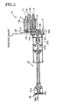
- FIGs. 1 to 6 show an embodiment of the ink trap apparatus of the invention which is applied to a printing machine for printing a body of a can in which FIG. 1 is a schematic front view of the entire apparatus, FIG. 2 is a schematic plan view of the entire apparatus, FIG. 3 is an enlarged front view, FIG. 4 is a sectional view showing respective rollers in developed views, FIGs. 5A and 5B are explanatory views of the contacting and withdrawing mechanism of the trap roller and FIGs. 6A, 6B and 6C are explanatory views of the blanket position detection means.
- This ink trap apparatus 10 is attached to a printer 2 for conducting transfer printing to a can body 1 and the ink trap apparatus 10 removes surplus ink or blurring ink before entering a normal printing operation.
- the printer 2 transfers ink from a plurality of unillustrated printing heads which constitute an ink supply unit to a plurality (e.g., 12) of blankets 4 of a blanket wheel 3, and performs transfer printing from each of the blankets 4 to each of can bodies 1 which is an object to be printed and is continuously supplied.
- this ink trap apparatus 10 removes surplus ink or blurring ink before the normal printing operation by causing a film F in the form of a belt to contact each of the blankets 4 and transfer the ink to the film F.
- this ink trap apparatus 10 there is provided a trap roller 11 on which the film F is wound via a contacting and withdrawing mechanism 12 which causes the trap roller 11 to contact the blanket 4 and withdraw from it.
- a feed shaft 13 for feeding out the film F which is wound about the feed shaft 13 in the form of a roll.
- a wind-up shaft 15 having a wind-up core 14 on which the film F after the ink trap is wound up.
- a drive roller 16 is provided between the trap roller 11 and the wind-up shaft 15 for pulling out the film F.
- an assisting roller 17 is provided adjacent to the trap roller 11 and on the downstream side of the drive roller 16
- an assisting roller 18 is provided adjacent to the drive roller 16 so as to increase the winding contact angle of the film F.
- the two rollers 11 and 16 other than the two assisting rollers 17 and 18 and the two shafts 13 and 15 are driven and rotated with a toothed belt 19 as will be described later.
- the trap roller 11 is rotatably mounted on a support shaft 11a which is attached on one end thereof to a frame 20 via an eccentric shaft 12a which constitutes a part of the contacting and withdrawing mechanism 12.
- the toothed belt 19 is wound on a pulley 11b attached to the base end portion of the trap roller 11 to drive the trap roller 11 for rotation.
- An operation arm 12b is attached to the eccentric shaft 12a of the contacting and withdrawing mechanism 12.
- an air cylinder 12c which is connected to one end portion of the operation arm 12b and functions as an actuator, the trap roller 11 which is rotated on the eccentric shaft 12a is caused to contact the blanket 4 in an overlapping manner and withdraw to a position where the trap roller 11 does not contact the blanket 4.
- the contacting and withdrawing mechanism 12 for enabling the trap roller 11 to contact the blanket 4 and withdraw from it is composed of the eccentric shaft 12a which supports the trap roller 11 and the actuator (in the present embodiment, the air cylinder 11 functions as the actuator) and, by this simple structure, the trap roller 11 can be brought to a contact position or to a withdrawn position.
- a fixed shaft 21a is mounted on the frame 20 in parallel to the support shaft 11a and the tip end portion of the support shaft 11a is supported by a support arm 21b provided at the tip end portion of the fixed shaft 21a.
- Toe-in of the trap roller 11 can be adjusted by an adjusting screw 21c which adjusts length of the support arm 21b.
- the amount of overlap between the trap roller 11 and the blanket 4 is adjusted to a value of, e.g., about 0.3mm.
- the amount of overlap varies with rigidity of the trap roller 11 and the support shaft 11a, the amount of overall is set to a value between about 0.3mm and about 0.6mm having regard to deflection of the end portion, and clearance at the withdrawn position is set at about 0.1mm.
- the outer diameter of the trap roller 11 is set to about the same diameter of the can body 1 so that, by one rotation of the trap roller 1, transfer printing is made from each blanket 4 to the can body 1.
- the feed shaft 13 about which the film F is wound in the form of a coil for feeding out is provided on the upstream side of the trap roller 11.
- the feed shaft 13 is rotatably mounted on a support shaft 13a which is fixedly mounted on the frame 20.
- a core member of the film F is fitted on the feed shaft 13 and fixed to the feed shaft 13 by tightening a nut 13b.
- At the end portion of the feed shaft 13 is fixedly mounted a pulley 13c via a friction transmitting mechanism 22 which is made of, e.g., a ball plunger 22a so that the pulley 12c can be driven for rotation with the toothed belt 19.
- the film F can be fed out with this change in the speed of rotation being absorbed by the ball plunger 22a.
- the friction transmitting force of the ball plunger 22a can be adjusted by changing clearance of the ball plunger 22a.
- the wind-up shaft 15 on which a wind-up core member 14 is fixedly mounted for winding up the film F in the form of a coil is provided on the downstream side of the trap roller 11.
- the wind-up shaft 15 is rotatably mounted on a support shaft 15a which is fixedly mounted on the frame 20.
- flange plates 14a in the form of a disk are provided on both sides of the wind-up core member 14 and these flange plates 14a are fixed to the wind-up shaft 15 by tightening a nut 15b.
- a pulley 15c At the base end portion of the wind-up shaft 15 is fixedly mounted a pulley 15c via a friction transmitting mechanism 22 which is made of, e.g., a ball plunger 22a so that the pulley 15c can be driven for rotation with the toothed belt 19.
- a friction transmitting mechanism 22 which is made of, e.g., a ball plunger 22a so that the pulley 15c can be driven for rotation with the toothed belt 19.
- slits for example may be formed on the cylindrical surface of the core member 14 and a spacer may be inserted in each of the slits to maintain a predetermined outer diameter. By removing these spacers, the outer diameter can be reduced.
- the wind-up core member 14 for winding up the film F on the wind-up shaft 15 in such a manner that its outer diameter can be reduced, the film F to which the ink is adhered can be separated in a simple manner for disposal.
- the drive roller 16 is provided between the trap roller 11 and the wind-up shaft 15 for accurately pulling out the film F.
- the drive roller 11 is rotatably mounted on a support shaft 16a which is fixedly mounted on the frame 20.
- a pulley 16b is fixedly mounted at the base end portion of the drive roller 16 and the toothed belt 19 is wound on the pulley 16b for driving the drive roller 16 for rotation.
- spikes 16c are provided on the drive roller 16 at an equal interval in the circumferential direction for increasing the force to pull out the film F.
- sixteen spikes 16c are provided in the circumferential direction and three rows of spikes are provided in the axial direction in such a manner that the spikes project from the surface of the drive roller 16 by about 2mm.
- an assisting roller 17 is provided on the upstream side of the trap roller 11 and an assisting roller 18 is provided on the downstream side of the drive roller 16.
- These rollers 17 and 18 rotatably mounted on a support shaft 17a and a support shaft 18a respectively.
- a fast-drying silicone resin for example, is coated as an ink adhesion preventing layer 23.
- a drive pulley 24 which is driven for rotation is mounted on a drive shaft 24a fixedly mounted on the frame 20.
- the endless toothed belt 19 is wound on the drive pulley 24, the pulley 11b of the trap roller 11, the pulley 13c of the feed shaft 13, the pulley 15c of the wind-up shaft 15 and the pulley 16b of the drive roller 16.
- the toothed belt 19 is stretched at a constant force by means of a timing belt tightener 25 in such a manner that a constant force is applied to the toothed belt 19 even when the position of the trap roller 11 is changed by the contacting and withdrawing mechanism 12.
- the ink trap apparatus 10 can be fixed to a printer frame of the main body of the printer 2 by means of a frame fixing bolt 26 in such a manner that the position of the frame 20 can be adjusted through a slot in which the bolt 26 is inserted.
- an input shaft 27a is provided on the opposite side of the trap roller 11 on the frame 20 as a drive mechanism for driving the drive pulley 24.
- an input pulley 27b On both ends of this input shaft 27a, there are attached an input pulley 27b and an output pulley 27c.
- the output pulley 27c is connected to an electromagnetic clutch 27i which is mounted on the input shaft 27a so that the on-off control of power to the ink trap apparatus 10 can be made.
- An endless toothed belt 27e is stretched between the output pulley 27c and a transmission pulley 27j provide on the drive shaft 24a via two idling pulleys 27d.
- An endless toothed belt 27h is stretched between the input pulley 27b and a pulley 27f of a rotary shaft in a drive gear box of the printer 2 via an idling pulley 27g.
- the driving force of the printer 2 is transmitted to the input shaft 27a and then to the drive pulley 24 via the input shaft 27a to drive the ink trap apparatus 10.
- the pulley ratio of the pulley 27f of the rotary shaft in the drive gear box of the printer 2 is so set that the pulley 27f will rotate six rotations, for example, relative to one rotation of the blanket wheel 3.
- a rotation position detection means 28 for the blanket 4 e.g., a rotation position detection disk 28a which is formed with a recess corresponding to the position of the blanket 4.
- Photo-sensors 28b are provided across the rotation position detection disk 28a and an on-off signal corresponding to the position of the blanket 4 is thereby output.
- a detection signal of this rotation position detection disk 28a is input to an unillustrated control unit which constitutes a control means which controls the air cylinder of 12c of the contacting and withdrawing mechanism 12 in such a manner that the mechanism 12 is brought to the contact position at a selected interval between e.g., 12 blankets 4.
- control means controls the air cylinder 12c of the mechanism 12 in such a manner that, after completion of the ink trap by transferring the ink by causing the mechanism 12 to contact each of the blankets 4 by a predetermined number of times, the mechanism 12 is brought back to the withdrawn position.
- the position detection means instead of the rotation position detection disc, other detection means may be employed.
- a rotary encoder may be employed to detect the rotation angle of e.g., the blanket wheel 3 of the printer 2 and thereby detect the position of the blanket 4.
- a high-density polyethylene film for example, may be used.
- a polyethylene film having an ink transfer surface to which a corona discharge treatment has been applied with a thickness of 20 ⁇ m may be used.
- the film F not only the above described film, but any material such as plastic, paper, cloth or a composite material thereof that can at least remove blurring ink and does not cause slipping or a wrinkle relative to the blanket may be used.
- a plastic film is particularly suitable.
- thickness of the film any thickness will be acceptable so long as the film can be fed out from a state of roll.
- the film F in the form of a coil is mounted on the feed shaft 13 of the ink trap apparatus 10 and the foremost end portion of the film F is attached to the wind-up core 14 of the wind-up shaft 15 in such a manner that the film F is wound on the trap roller 11, the drive roller 16 and the assisting rollers 17 and 18.
- the position of the blankets 4 of the blanket wheel 3 to which the ink is transferred is detected by the rotation position detection disk 28a of the rotation position detection means 28 and the photo-sensors 28b or a rotary encoder.
- the trap roller 11 is caused to advance to the contact position by the contacting and withdrawing mechanism 12 at a timing of the interval between the blankets 4 while the film F of the ink trap apparatus 10 is fed out by the driving force from the printer 2.
- the film F wound on the trap roller 11 is fed while the film F is pressed to each blanket 4 on which the ink has been transferred in an overlapping state whereby surplus ink and blurring ink are transferred to the surface of the film F.
- the film F to which the ink has been transferred is wound up by the wind-up shaft 15 through the wind-up core 14 and, thus, an always clean film surface contacts the blankets 4.
- the interval between the blankets 4 is detected by the position detection means 28 and the trap roller 11 is withdrawn for finishing the ink trap.
- the number of cans which are thrown away can be reduced significantly as compared to a case where the ink trap is made by using a can body which is an object to be printed. According to a tentative calculation, the cost can be reduced to one sixteenth.
- the ink trap can be made by contacting an always clean film to each blanket and, as compared to the prior art case in which the ink transferred to an auxiliary roll is immersed in a solvent and then wiped off, there is no deterioration of cleanliness of the surface of the auxiliary roll with repetition of the ink trap and, therefore, the ink trap can be made in a stable state.
- the driving force necessary for feeding and winding up of the film F is provided by the printer 2 and, therefore, provision of a speed controller and a tension controller is not necessary and, as a result, the structure of the apparatus can be simplified and, moreover, detection of timing of contacting and withdrawing can be made simply by detecting the position of the blanket.
- the ink trap is made in the foregoing manner.
- finishing varnish is coated after printing.
- trapping is necessary until the amount of coating of varnish becomes stable.
- a removing means 30 for trap of a finishing coating is provided.
- a removing roller 30a is caused to contact a lower portion of an applicator roller 31 and the removing roller 30a is driven for rotation by driving force of an anilox roller 32.
- a removing blade 30b is provided to contact the removing roller 30.
- surplus ink or blurring ink can be removed in a simple manner during a period of time from starting or re-staring of the printer till entering a normal printing operation without necessity for operating a printer by using an object to be printed which becomes a product.
- the method and apparatus are particularly useful for application to a printer of a drink can or the like for preventing production of a printed can which is not suitable as a product.
Landscapes
- Inking, Control Or Cleaning Of Printing Machines (AREA)
Applications Claiming Priority (1)
| Application Number | Priority Date | Filing Date | Title |
|---|---|---|---|
| PCT/JP2007/055585 WO2008111235A1 (fr) | 2007-03-13 | 2007-03-13 | Procédé et dispositif pour piéger de l'encre |
Publications (3)
| Publication Number | Publication Date |
|---|---|
| EP2123457A1 true EP2123457A1 (fr) | 2009-11-25 |
| EP2123457A4 EP2123457A4 (fr) | 2012-06-27 |
| EP2123457B1 EP2123457B1 (fr) | 2013-07-10 |
Family
ID=39759183
Family Applications (1)
| Application Number | Title | Priority Date | Filing Date |
|---|---|---|---|
| EP07739028.4A Not-in-force EP2123457B1 (fr) | 2007-03-13 | 2007-03-13 | Dispositif pour piéger de l'encre |
Country Status (5)
| Country | Link |
|---|---|
| US (1) | US8635954B2 (fr) |
| EP (1) | EP2123457B1 (fr) |
| KR (1) | KR101152701B1 (fr) |
| CN (1) | CN101835614B (fr) |
| WO (1) | WO2008111235A1 (fr) |
Families Citing this family (5)
| Publication number | Priority date | Publication date | Assignee | Title |
|---|---|---|---|---|
| KR101744809B1 (ko) * | 2015-10-15 | 2017-06-08 | 현대자동차 주식회사 | 곡면 스크린 상의 터치 드래그 제스처를 인식하는 방법 및 장치 |
| US10603897B2 (en) * | 2017-12-19 | 2020-03-31 | Xerox Corporation | Ink splitting multi-roll cleaner for a variable data lithography system |
| CN112743615A (zh) * | 2020-12-22 | 2021-05-04 | 安徽骄阳软门有限责任公司 | 一种门帘加工机构 |
| CN114643779A (zh) * | 2022-04-06 | 2022-06-21 | 苏州全彩机械设备有限公司 | 橡皮布自动清洗装置 |
| EP4698379A2 (fr) * | 2023-04-21 | 2026-02-25 | Stolle Machinery Company, LLC | Dispositif de décoration de boîte et mécanisme de verrouillage de cylindre porte-plaque, système de remplacement et système de réglage de synchronisation et procédé associé |
Family Cites Families (25)
| Publication number | Priority date | Publication date | Assignee | Title |
|---|---|---|---|---|
| US3763778A (en) * | 1972-02-28 | 1973-10-09 | Ryco Graphic Mfg | Method for surface maintenance of printing press blanket cylinders |
| US4088074A (en) * | 1974-11-25 | 1978-05-09 | Dahlgren Harold P | Apparatus for inking printing plates |
| US4757763A (en) * | 1979-04-19 | 1988-07-19 | Baldwin Technology Corporation | Automatic blanket cylinder cleaner |
| IT1130118B (it) * | 1980-04-16 | 1986-06-11 | Olivetti & Co Spa | Apparecchiatura di deposito di valori in busta con dispensazione automatica delle buste |
| JPS5872457A (ja) | 1981-10-27 | 1983-04-30 | Toppan Printing Co Ltd | 凹版オフセツト印刷用ブランケツトクリ−ニング装置 |
| JPS58208055A (ja) * | 1982-05-27 | 1983-12-03 | Ryobi Ltd | 両面印刷機 |
| JPS59106967A (ja) * | 1982-12-13 | 1984-06-20 | Nippon H Kk | プリプリンテイング方法および装置 |
| JPH028055A (ja) * | 1988-06-28 | 1990-01-11 | Nippon Baldwin Kk | 印刷機のシリンダ洗浄装置及び方法 |
| EP0388757A1 (fr) * | 1989-03-20 | 1990-09-26 | Elettra S.R.L. | Dispositif presseur dans un dispositif à nettoyer le cylindre porte-caoutchouc d'une presse d'imprimerie |
| JPH0739176B2 (ja) | 1990-06-06 | 1995-05-01 | 日本ボールドウイン株式会社 | 印刷機のシリンダ洗浄装置 |
| US5265532A (en) * | 1991-03-08 | 1993-11-30 | Sequa Corporation | Apparatus and method for decorating cylindrical containers |
| DE4211310A1 (de) * | 1992-04-04 | 1993-10-28 | Heidelberger Druckmasch Ag | Vorrichtung zur Reinigung farbführender Oberflächen in Druckwerken |
| JPH0622892A (ja) | 1992-07-10 | 1994-02-01 | Asahi Chem Ind Co Ltd | ワイピングクロス |
| JPH09123428A (ja) | 1995-11-01 | 1997-05-13 | Tani Denki Kogyo Kk | スクリーン印刷装置のスクリーン版のクリーニングの方法と装置 |
| JPH08132598A (ja) | 1994-11-10 | 1996-05-28 | Mitsubishi Heavy Ind Ltd | ブランケット胴、圧胴共用洗浄装置 |
| CA2169236C (fr) | 1995-02-18 | 2002-01-29 | Okie Tani | Dispositif servant au nettoyage d'un ecran d'impression utilise en serigraphie |
| JPH09123399A (ja) | 1995-10-30 | 1997-05-13 | Showa Seiki Kk | 缶胴ブランクのオフセット印刷方法 |
| JP3790339B2 (ja) | 1997-09-29 | 2006-06-28 | 三菱製紙株式会社 | 印刷機ブランケット洗浄用不織布 |
| US5979316A (en) * | 1997-09-30 | 1999-11-09 | Corrugated Gear & Services, Inc. | Belt-driven printer-cutter machine for corrugated paperboard of varying thickness |
| EP0936067B1 (fr) * | 1998-02-10 | 2003-12-03 | Baldwin-Japan Ltd. | Dispositif pour nettoyer un cylindre |
| JP2001138484A (ja) * | 1999-11-10 | 2001-05-22 | Hokkai Can Co Ltd | 2ピース缶体のニス塗工装置 |
| JP3885668B2 (ja) * | 2002-06-12 | 2007-02-21 | コニカミノルタホールディングス株式会社 | 平版印刷版材料および平版印刷版材料の固定方法 |
| JP2005035003A (ja) * | 2003-07-15 | 2005-02-10 | Konica Minolta Medical & Graphic Inc | 版下シート材料、版掛け方法及び印刷方法 |
| DE102005003083A1 (de) * | 2005-01-22 | 2006-07-27 | Baldwin Germany Gmbh | Druckmaschinen-Reinigungsvorrichtung |
| JP5076297B2 (ja) | 2005-09-15 | 2012-11-21 | 東洋製罐株式会社 | インキトラップ装置 |
-
2007
- 2007-03-13 US US12/449,736 patent/US8635954B2/en not_active Expired - Fee Related
- 2007-03-13 EP EP07739028.4A patent/EP2123457B1/fr not_active Not-in-force
- 2007-03-13 CN CN200780052916XA patent/CN101835614B/zh not_active Expired - Fee Related
- 2007-03-13 KR KR1020097019420A patent/KR101152701B1/ko not_active Expired - Fee Related
- 2007-03-13 WO PCT/JP2007/055585 patent/WO2008111235A1/fr not_active Ceased
Also Published As
| Publication number | Publication date |
|---|---|
| US20100005988A1 (en) | 2010-01-14 |
| EP2123457B1 (fr) | 2013-07-10 |
| EP2123457A4 (fr) | 2012-06-27 |
| CN101835614B (zh) | 2013-03-20 |
| CN101835614A (zh) | 2010-09-15 |
| WO2008111235A1 (fr) | 2008-09-18 |
| KR20100005031A (ko) | 2010-01-13 |
| KR101152701B1 (ko) | 2012-06-15 |
| US8635954B2 (en) | 2014-01-28 |
Similar Documents
| Publication | Publication Date | Title |
|---|---|---|
| JP7123119B2 (ja) | 印刷システムのためのエンドレスフレキシブルベルト | |
| EP2123457B1 (fr) | Dispositif pour piéger de l'encre | |
| CN101840187B (zh) | 图像定影装置 | |
| JP2016537225A (ja) | 凹版印刷機械及び凹版印刷機械を備える印刷施設 | |
| JP7085132B2 (ja) | ロールユニット、ロール装置、ヘッドメンテナンス装置、液体を吐出する装置 | |
| JPH1173042A (ja) | 湿式電子写真方式印刷器の転写ローラクリーニング装置 | |
| TW200920604A (en) | Paper sheet coating apparatus | |
| KR980008569A (ko) | 웹 가이드 롤러 청정방법 및 장치 | |
| CN101346229B (zh) | 控制用于印张材料的处理机的方法 | |
| JP5076297B2 (ja) | インキトラップ装置 | |
| CN110248810B (zh) | 具有用于模板擦拭器组件的可控张力装置的模板印刷机 | |
| CN111688352B (zh) | 间歇印刷机 | |
| CN221698247U (zh) | 一种柔版印刷机 | |
| DE102012023389A1 (de) | Verfahren zum Reinigen eines Zwischenträgers für den indirekten Druck | |
| WO2008093157A1 (fr) | Procédé et appareil d'impression sur toile | |
| JP7163698B2 (ja) | 媒体搬送装置及び液体を吐出する装置 | |
| JP2007522979A (ja) | 印刷の品質を改善するためのインク着けローラの駆動機構 | |
| CN101269573A (zh) | 清洁设备 | |
| JPH0976473A (ja) | 印刷機シリンダの洗浄方法および装置 | |
| CN105555537B (zh) | 用于在印刷机中将滚筒包衬与承印材料变化相适配的方法 | |
| JP2010072066A (ja) | クリーニング装置、定着装置、画像形成装置、及びクリーニング方法 | |
| US20030235445A1 (en) | Fixing apparatus | |
| JP2025126622A (ja) | 孔版印刷装置 | |
| CN118003757A (zh) | 印刷机的施加辊的控制 | |
| RU58444U1 (ru) | Устройство флексографическое для нанесения печати на полимерную ленту |
Legal Events
| Date | Code | Title | Description |
|---|---|---|---|
| PUAI | Public reference made under article 153(3) epc to a published international application that has entered the european phase |
Free format text: ORIGINAL CODE: 0009012 |
|
| 17P | Request for examination filed |
Effective date: 20090821 |
|
| AK | Designated contracting states |
Kind code of ref document: A1 Designated state(s): AT BE BG CH CY CZ DE DK EE ES FI FR GB GR HU IE IS IT LI LT LU LV MC MT NL PL PT RO SE SI SK TR |
|
| DAX | Request for extension of the european patent (deleted) | ||
| A4 | Supplementary search report drawn up and despatched |
Effective date: 20120525 |
|
| RIC1 | Information provided on ipc code assigned before grant |
Ipc: B41F 35/06 20060101AFI20120521BHEP |
|
| RAP1 | Party data changed (applicant data changed or rights of an application transferred) |
Owner name: TOYO SEIKAN KAISHA, LTD. |
|
| GRAP | Despatch of communication of intention to grant a patent |
Free format text: ORIGINAL CODE: EPIDOSNIGR1 |
|
| GRAS | Grant fee paid |
Free format text: ORIGINAL CODE: EPIDOSNIGR3 |
|
| GRAA | (expected) grant |
Free format text: ORIGINAL CODE: 0009210 |
|
| AK | Designated contracting states |
Kind code of ref document: B1 Designated state(s): AT BE BG CH CY CZ DE DK EE ES FI FR GB GR HU IE IS IT LI LT LU LV MC MT NL PL PT RO SE SI SK TR |
|
| REG | Reference to a national code |
Ref country code: GB Ref legal event code: FG4D |
|
| REG | Reference to a national code |
Ref country code: CH Ref legal event code: EP Ref country code: AT Ref legal event code: REF Ref document number: 620716 Country of ref document: AT Kind code of ref document: T Effective date: 20130715 |
|
| REG | Reference to a national code |
Ref country code: IE Ref legal event code: FG4D |
|
| REG | Reference to a national code |
Ref country code: DE Ref legal event code: R096 Ref document number: 602007031548 Country of ref document: DE Effective date: 20130905 |
|
| PG25 | Lapsed in a contracting state [announced via postgrant information from national office to epo] |
Ref country code: SI Free format text: LAPSE BECAUSE OF FAILURE TO SUBMIT A TRANSLATION OF THE DESCRIPTION OR TO PAY THE FEE WITHIN THE PRESCRIBED TIME-LIMIT Effective date: 20130710 |
|
| REG | Reference to a national code |
Ref country code: AT Ref legal event code: MK05 Ref document number: 620716 Country of ref document: AT Kind code of ref document: T Effective date: 20130710 |
|
| REG | Reference to a national code |
Ref country code: NL Ref legal event code: VDEP Effective date: 20130710 |
|
| REG | Reference to a national code |
Ref country code: LT Ref legal event code: MG4D |
|
| PG25 | Lapsed in a contracting state [announced via postgrant information from national office to epo] |
Ref country code: PT Free format text: LAPSE BECAUSE OF FAILURE TO SUBMIT A TRANSLATION OF THE DESCRIPTION OR TO PAY THE FEE WITHIN THE PRESCRIBED TIME-LIMIT Effective date: 20131111 Ref country code: SE Free format text: LAPSE BECAUSE OF FAILURE TO SUBMIT A TRANSLATION OF THE DESCRIPTION OR TO PAY THE FEE WITHIN THE PRESCRIBED TIME-LIMIT Effective date: 20130710 Ref country code: IS Free format text: LAPSE BECAUSE OF FAILURE TO SUBMIT A TRANSLATION OF THE DESCRIPTION OR TO PAY THE FEE WITHIN THE PRESCRIBED TIME-LIMIT Effective date: 20131110 Ref country code: LT Free format text: LAPSE BECAUSE OF FAILURE TO SUBMIT A TRANSLATION OF THE DESCRIPTION OR TO PAY THE FEE WITHIN THE PRESCRIBED TIME-LIMIT Effective date: 20130710 Ref country code: CY Free format text: LAPSE BECAUSE OF FAILURE TO SUBMIT A TRANSLATION OF THE DESCRIPTION OR TO PAY THE FEE WITHIN THE PRESCRIBED TIME-LIMIT Effective date: 20130814 Ref country code: BE Free format text: LAPSE BECAUSE OF FAILURE TO SUBMIT A TRANSLATION OF THE DESCRIPTION OR TO PAY THE FEE WITHIN THE PRESCRIBED TIME-LIMIT Effective date: 20130710 Ref country code: AT Free format text: LAPSE BECAUSE OF FAILURE TO SUBMIT A TRANSLATION OF THE DESCRIPTION OR TO PAY THE FEE WITHIN THE PRESCRIBED TIME-LIMIT Effective date: 20130710 |
|
| PG25 | Lapsed in a contracting state [announced via postgrant information from national office to epo] |
Ref country code: LV Free format text: LAPSE BECAUSE OF FAILURE TO SUBMIT A TRANSLATION OF THE DESCRIPTION OR TO PAY THE FEE WITHIN THE PRESCRIBED TIME-LIMIT Effective date: 20130710 Ref country code: FI Free format text: LAPSE BECAUSE OF FAILURE TO SUBMIT A TRANSLATION OF THE DESCRIPTION OR TO PAY THE FEE WITHIN THE PRESCRIBED TIME-LIMIT Effective date: 20130710 Ref country code: ES Free format text: LAPSE BECAUSE OF FAILURE TO SUBMIT A TRANSLATION OF THE DESCRIPTION OR TO PAY THE FEE WITHIN THE PRESCRIBED TIME-LIMIT Effective date: 20131021 Ref country code: GR Free format text: LAPSE BECAUSE OF FAILURE TO SUBMIT A TRANSLATION OF THE DESCRIPTION OR TO PAY THE FEE WITHIN THE PRESCRIBED TIME-LIMIT Effective date: 20131011 Ref country code: PL Free format text: LAPSE BECAUSE OF FAILURE TO SUBMIT A TRANSLATION OF THE DESCRIPTION OR TO PAY THE FEE WITHIN THE PRESCRIBED TIME-LIMIT Effective date: 20130710 Ref country code: NL Free format text: LAPSE BECAUSE OF FAILURE TO SUBMIT A TRANSLATION OF THE DESCRIPTION OR TO PAY THE FEE WITHIN THE PRESCRIBED TIME-LIMIT Effective date: 20130710 |
|
| PG25 | Lapsed in a contracting state [announced via postgrant information from national office to epo] |
Ref country code: CY Free format text: LAPSE BECAUSE OF FAILURE TO SUBMIT A TRANSLATION OF THE DESCRIPTION OR TO PAY THE FEE WITHIN THE PRESCRIBED TIME-LIMIT Effective date: 20130710 |
|
| PG25 | Lapsed in a contracting state [announced via postgrant information from national office to epo] |
Ref country code: RO Free format text: LAPSE BECAUSE OF FAILURE TO SUBMIT A TRANSLATION OF THE DESCRIPTION OR TO PAY THE FEE WITHIN THE PRESCRIBED TIME-LIMIT Effective date: 20130710 Ref country code: SK Free format text: LAPSE BECAUSE OF FAILURE TO SUBMIT A TRANSLATION OF THE DESCRIPTION OR TO PAY THE FEE WITHIN THE PRESCRIBED TIME-LIMIT Effective date: 20130710 Ref country code: CZ Free format text: LAPSE BECAUSE OF FAILURE TO SUBMIT A TRANSLATION OF THE DESCRIPTION OR TO PAY THE FEE WITHIN THE PRESCRIBED TIME-LIMIT Effective date: 20130710 Ref country code: DK Free format text: LAPSE BECAUSE OF FAILURE TO SUBMIT A TRANSLATION OF THE DESCRIPTION OR TO PAY THE FEE WITHIN THE PRESCRIBED TIME-LIMIT Effective date: 20130710 Ref country code: EE Free format text: LAPSE BECAUSE OF FAILURE TO SUBMIT A TRANSLATION OF THE DESCRIPTION OR TO PAY THE FEE WITHIN THE PRESCRIBED TIME-LIMIT Effective date: 20130710 |
|
| PLBE | No opposition filed within time limit |
Free format text: ORIGINAL CODE: 0009261 |
|
| STAA | Information on the status of an ep patent application or granted ep patent |
Free format text: STATUS: NO OPPOSITION FILED WITHIN TIME LIMIT |
|
| PG25 | Lapsed in a contracting state [announced via postgrant information from national office to epo] |
Ref country code: IT Free format text: LAPSE BECAUSE OF FAILURE TO SUBMIT A TRANSLATION OF THE DESCRIPTION OR TO PAY THE FEE WITHIN THE PRESCRIBED TIME-LIMIT Effective date: 20130710 |
|
| 26N | No opposition filed |
Effective date: 20140411 |
|
| REG | Reference to a national code |
Ref country code: DE Ref legal event code: R097 Ref document number: 602007031548 Country of ref document: DE Effective date: 20140411 |
|
| PG25 | Lapsed in a contracting state [announced via postgrant information from national office to epo] |
Ref country code: LU Free format text: LAPSE BECAUSE OF FAILURE TO SUBMIT A TRANSLATION OF THE DESCRIPTION OR TO PAY THE FEE WITHIN THE PRESCRIBED TIME-LIMIT Effective date: 20140313 |
|
| REG | Reference to a national code |
Ref country code: CH Ref legal event code: PL |
|
| REG | Reference to a national code |
Ref country code: IE Ref legal event code: MM4A |
|
| PG25 | Lapsed in a contracting state [announced via postgrant information from national office to epo] |
Ref country code: CH Free format text: LAPSE BECAUSE OF NON-PAYMENT OF DUE FEES Effective date: 20140331 Ref country code: IE Free format text: LAPSE BECAUSE OF NON-PAYMENT OF DUE FEES Effective date: 20140313 Ref country code: LI Free format text: LAPSE BECAUSE OF NON-PAYMENT OF DUE FEES Effective date: 20140331 |
|
| PG25 | Lapsed in a contracting state [announced via postgrant information from national office to epo] |
Ref country code: MT Free format text: LAPSE BECAUSE OF FAILURE TO SUBMIT A TRANSLATION OF THE DESCRIPTION OR TO PAY THE FEE WITHIN THE PRESCRIBED TIME-LIMIT Effective date: 20130710 |
|
| REG | Reference to a national code |
Ref country code: FR Ref legal event code: PLFP Year of fee payment: 10 |
|
| PG25 | Lapsed in a contracting state [announced via postgrant information from national office to epo] |
Ref country code: BG Free format text: LAPSE BECAUSE OF FAILURE TO SUBMIT A TRANSLATION OF THE DESCRIPTION OR TO PAY THE FEE WITHIN THE PRESCRIBED TIME-LIMIT Effective date: 20130710 Ref country code: MC Free format text: LAPSE BECAUSE OF FAILURE TO SUBMIT A TRANSLATION OF THE DESCRIPTION OR TO PAY THE FEE WITHIN THE PRESCRIBED TIME-LIMIT Effective date: 20130710 |
|
| PG25 | Lapsed in a contracting state [announced via postgrant information from national office to epo] |
Ref country code: HU Free format text: LAPSE BECAUSE OF FAILURE TO SUBMIT A TRANSLATION OF THE DESCRIPTION OR TO PAY THE FEE WITHIN THE PRESCRIBED TIME-LIMIT; INVALID AB INITIO Effective date: 20070313 Ref country code: TR Free format text: LAPSE BECAUSE OF FAILURE TO SUBMIT A TRANSLATION OF THE DESCRIPTION OR TO PAY THE FEE WITHIN THE PRESCRIBED TIME-LIMIT Effective date: 20130710 |
|
| REG | Reference to a national code |
Ref country code: FR Ref legal event code: PLFP Year of fee payment: 11 |
|
| REG | Reference to a national code |
Ref country code: FR Ref legal event code: PLFP Year of fee payment: 12 |
|
| PGFP | Annual fee paid to national office [announced via postgrant information from national office to epo] |
Ref country code: DE Payment date: 20240320 Year of fee payment: 18 Ref country code: GB Payment date: 20240320 Year of fee payment: 18 |
|
| PGFP | Annual fee paid to national office [announced via postgrant information from national office to epo] |
Ref country code: FR Payment date: 20240322 Year of fee payment: 18 |
|
| REG | Reference to a national code |
Ref country code: DE Ref legal event code: R119 Ref document number: 602007031548 Country of ref document: DE |
|
| GBPC | Gb: european patent ceased through non-payment of renewal fee |
Effective date: 20250313 |
|
| PG25 | Lapsed in a contracting state [announced via postgrant information from national office to epo] |
Ref country code: DE Free format text: LAPSE BECAUSE OF NON-PAYMENT OF DUE FEES Effective date: 20251001 |
|
| PG25 | Lapsed in a contracting state [announced via postgrant information from national office to epo] |
Ref country code: GB Free format text: LAPSE BECAUSE OF NON-PAYMENT OF DUE FEES Effective date: 20250313 |
|
| PG25 | Lapsed in a contracting state [announced via postgrant information from national office to epo] |
Ref country code: FR Free format text: LAPSE BECAUSE OF NON-PAYMENT OF DUE FEES Effective date: 20250331 |