EP2128354A2 - Élément mural en bois - Google Patents
Élément mural en bois Download PDFInfo
- Publication number
- EP2128354A2 EP2128354A2 EP09003169A EP09003169A EP2128354A2 EP 2128354 A2 EP2128354 A2 EP 2128354A2 EP 09003169 A EP09003169 A EP 09003169A EP 09003169 A EP09003169 A EP 09003169A EP 2128354 A2 EP2128354 A2 EP 2128354A2
- Authority
- EP
- European Patent Office
- Prior art keywords
- wall
- support
- elements
- element according
- support elements
- Prior art date
- Legal status (The legal status is an assumption and is not a legal conclusion. Google has not performed a legal analysis and makes no representation as to the accuracy of the status listed.)
- Withdrawn
Links
Images


Classifications
-
- E—FIXED CONSTRUCTIONS
- E04—BUILDING
- E04C—STRUCTURAL ELEMENTS; BUILDING MATERIALS
- E04C2/00—Building elements of relatively thin form for the construction of parts of buildings, e.g. sheet materials, slabs, or panels
- E04C2/02—Building elements of relatively thin form for the construction of parts of buildings, e.g. sheet materials, slabs, or panels characterised by specified materials
- E04C2/10—Building elements of relatively thin form for the construction of parts of buildings, e.g. sheet materials, slabs, or panels characterised by specified materials of wood, fibres, chips, vegetable stems, or the like; of plastics; of foamed products
- E04C2/12—Building elements of relatively thin form for the construction of parts of buildings, e.g. sheet materials, slabs, or panels characterised by specified materials of wood, fibres, chips, vegetable stems, or the like; of plastics; of foamed products of solid wood
-
- E—FIXED CONSTRUCTIONS
- E04—BUILDING
- E04C—STRUCTURAL ELEMENTS; BUILDING MATERIALS
- E04C2/00—Building elements of relatively thin form for the construction of parts of buildings, e.g. sheet materials, slabs, or panels
- E04C2/44—Building elements of relatively thin form for the construction of parts of buildings, e.g. sheet materials, slabs, or panels characterised by the purpose
- E04C2/52—Building elements of relatively thin form for the construction of parts of buildings, e.g. sheet materials, slabs, or panels characterised by the purpose with special adaptations for auxiliary purposes, e.g. serving for locating conduits
- E04C2/521—Building elements of relatively thin form for the construction of parts of buildings, e.g. sheet materials, slabs, or panels characterised by the purpose with special adaptations for auxiliary purposes, e.g. serving for locating conduits serving for locating conduits; for ventilating, heating or cooling
Definitions
- the invention relates to a wooden wall element with a wall plate, which is made of disc-shaped support elements.
- the wall panels in the timber frame construction can be made of rod-shaped elements, in which the vertical loads are taken over by the rod-shaped supports and the stiffening forces of the endurenbeplankonne. It is necessary that the edge members of a wall plate formed from the sleepers and rams receive the resulting disk forces from the stiffening planking.
- the other possibility is to make the wall panels of sheet-like elements, which absorb both the vertical forces and the stiffening pulley forces in itself.
- the individual, formed from sheet-like elements wall plates are connected by means of coupling elements together shear stiff.
- facing shells can basically be installed in all types of construction, however, on the other hand, the better double-shell acoustic decoupling requires the strict separation of the supporting systems, including sleepers and crates. Since all the aforementioned sound improvement measures are very complicated and costly, and since such sound improvement measures are associated with a greater wall thickness and in turn with a loss of living space, in recent years, the production of wooden structures, especially using sheet-like elements increasingly less demand and instead lighter and thin-walled constructions are given preference.
- the timber construction wall element according to the invention has a wall plate
- the timber construction wall element according to the invention is formed as a single shell.
- Each of the wall panels forming a timber construction wall element is made of disc-shaped support elements, which are oriented in the vertical direction with their greater longitudinal extent compared to the width.
- the support elements forming a wall plate are provided in two support element planes and respectively arranged at a distance such that the distance between two adjacent support elements of one support element plane is at least largely or partially covered by a support element of the other support element plane.
- the support elements are interconnected via, for example, strip-shaped coupling elements.
- the coupling elements required for connecting the thrust forces between the individual support elements are arranged in the longitudinal direction of the wall plate so that they can act pliable and yielding transversely to the wall. Since the individual support elements can take over both vertical loads and stiffening forces within the wall plate, no additional surface planking must be used for stiffening. Since such surface skins do not have to transmit any stiffening forces and therefore do not have to be fastened to the sleepers and crates, sound bridges are also avoided in this region of the wall pane.
- the support elements interconnecting coupling elements are arranged between the adjacent longitudinal edges of each provided in another support element level support elements.
- each wall plate is first transferred to the support elements of the underlying support element level to be redirected from there via the coupling elements in the adjacent support element level, where the sound waves increasingly lose. Since the floor and / or ceiling-side connection provided strip-shaped thresholds are set back against the wall surface such that the provided on both sides of the wall plate surgeonnbeplankungen to the at least one floor and / or ceiling side threshold are kept at a distance, which are on the microwavenbeplankung Incident sound waves also not uncontrolled and disturbing registered over these thresholds in the building.
- the timber construction wall element according to the invention is only one shell and correspondingly thin, it can therefore also meet high sound requirements in housing.
- the wooden wall element according to the invention is highly resilient and statically flexible, so that it can accommodate large and small loads as required.
- the wooden wall element according to the invention is simple in planning and handling, since the versatility of each wood wall element supports a simple storage support, the small wall thickness significantly reduces the weight and the single-shell design facilitates the blank and the attachment of the timber wall element. Since the surface skins do not have an additional stiffening function, the most diverse surface finishes are possible.
- the wooden wall element according to the invention is therefore characterized by its versatility, its high load capacity, its associated with an additional living space low wall thickness and its high sound insulation and decoupling out.
- a preferred development according to the invention provides that the coupling elements are fastened to at least one, preferably only on one of the adjacent longitudinal edges of each provided in a different support element level support elements. It has been shown that the good sound insulation properties of the timber construction wall element according to the invention can be further increased if the coupling elements are attached only to one of the adjacent longitudinal edges of each provided in another support element level support elements. Even if the individual coupling elements are attached only to one of the adjacent longitudinal edges, they can advantageously limit a pivoting or bending movement of the support elements.
- the good sound insulation properties are additionally favored if the coupling elements arranged between the adjacent longitudinal edges of the support elements provided in a respective other support element level each extend at least over a partial region of the support element longitudinal edges.
- a preferred embodiment according to the invention provides that at least two, preferably three, each extending over a portion of the support element longitudinal edges coupling element are arranged between the adjacent longitudinal edges of each provided in another support element level support elements.
- the wall thickness of the timber construction wall element according to the invention can be additionally reduced if the support elements each have a fold at their, the wall center plane facing longitudinal edges, on which a coupling element is held.
- By means of such a design can be additionally Gain housing.
- the folds provided at the longitudinal edges of the support elements have a rebate depth which is equal to or greater than the thickness of the associated coupling element and / or have a rebate width which is equal to or greater than the width of the longitudinal edge of the fold overlapping the fold in the other support element level adjacent support element.
- a particularly advantageous and resilient embodiment according to the invention provides that the coupling elements are arranged in the longitudinal center plane of the wall plate.
- the coupling elements connect the support elements flexurally soft bending elastic and transverse to the wall plate.
- the coupling elements can be separated or insulated from the adjacent to them supporting elements by an intermediate insulating and / or elastomeric layer.
- a development according to the invention provides that at least some of the spaced apart from each other at a distance support elements of a support element level wall disk cavities for receiving at least one sound and / or thermal insulation, at least one space heater and / or at least one supply line are provided. In this way, the remaining between the support elements of a support element level wall disk cavities can be used advantageously without the structure or the thickness of the wall plate would have to be significantly changed.
- a particularly advantageous embodiment according to the invention for example, also for the production of a largely energy-self-sufficient passive house can be used, provides that provided in cavities of a wall plate heater is a Hypokasterhomung.
- the at least one support element of at least one support element plane is at least one, arranged in the support element plane, preferably horizontally oriented and intended to receive at least one supply line Supply channel has. It is particularly advantageous if the support elements at least one support element level each have at least one mutually aligned supply channel.
- coupling elements and the support elements are made of solid wood or plywood.
- coupling elements may additionally or alternatively be made of plywood.
- a timber wall element 1 in one schematic representation shown.
- the timber wall element 1 has a wall plate 2, which is made of disc-shaped support elements 3.
- the wall plate 2 of the timber wall element 1 forming support elements 3 are arranged in two support element levels A, B.
- the disc-shaped support elements 3 are oriented with their greater longitudinal extent compared to the width in the vertical direction.
- the support elements 3 provided in the support element planes A, B are each arranged at a distance such that the distance between two adjacent support elements 3 of one support element plane A, B is at least partially by a support element 3 of the other support element plane B, A is covered.
- the support elements 3 are connected to each other by means of strip-shaped coupling elements 4, which are held between the overlapping longitudinal edges of each arranged in a different support element level support elements 3.
- the coupling elements 4 are attached to both adjacent longitudinal edges of each provided in another support element level A, B support member, possibly even an additional sound insulation can be achieved if these coupling elements 4 only at one of each other adjacent longitudinal edges are held.
- At least one strip-shaped threshold 5 is provided.
- the timber construction wall element 1 shown here is formed as a single shell.
- the coupling elements 4 required for connecting the thrust forces between the individual support elements 3 of the timber-wall element 1 are arranged in the longitudinal direction of the wall plate 2 so that they can act pliable and yielding transversely to the wall. Since the individual support elements 3 can take over both vertical loads and stiffening forces within the wall plate 2, the surface coverings 6 need not additionally be used for stiffening. Since the bruisenbeplankitch 6 no stiffening forces have to be transmitted and therefore do not need to be attached to the thresholds 5, 2 sound bridges are avoided in this area of the wall plate.
- each wall plate 2 surface planking 6 sound waves they are first transferred to the support elements 3 of the underlying support element level A or B.
- 3rd . 5 and 6 is particularly well recognized that the sound waves are diverted from there via the coupling elements 4 in the adjacent support element level B and A, where the sound waves increasingly lose. Since the floor and / or ceiling-side connection provided strip-shaped sleepers 5 are set back relative to the wall disc surface such that the provided on both sides of the wall plate 2 bruisenbeplankung 6 is held at least one floor and / or ceiling-side threshold 5 at a distance the sound waves impinging on the surface planking 6 are not entered into the building in an uncontrolled and disturbing manner via these sleepers 5.
- the timber construction wall element 1 shown here only einschalig and is designed accordingly thin, so it can also meet high sound requirements in housing.
- the wooden wall element 1 is highly resilient and statically flexible, so that it can accommodate large and small loads depending on the requirements.
- the timber wall element 1 shown here is simple in planning and handling, since the versatility of this timber wall element 1 favors a simple storage, the single-shell design simplifies the blank and the attachment and the small wall thickness significantly reduces the weight. Since the surface planking 6 does not have to take on any additional stiffening function, the most varied surface finishes are possible.
- the timber construction wall element 1 shown here is therefore characterized by its versatility, its high load capacity, its associated with an additional housing gain low wall thickness and its high sound insulation and decoupling.
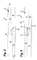
- the support elements 3 can also have a fold 7 at their longitudinal edges facing the wall disk center plane, on which a coupling element 4 is held.
- a rebate depth which is slightly larger than the thickness of the associated coupling element 4.
- these folds 7 have a fold width which is slightly larger than the width of the fold 7 overlapping longitudinal edge of the adjacent support element in the other plane support element 3.
- the Fig. 6 illustrated embodiment makes it possible to design the individual support elements 3 thicker and correspondingly more stable, without thereby the wall thickness or the wall structure of the wall plate 2 would have to be changed.
- FIG. 7 another embodiment of a timber wall element 10 is shown. Also in Fig. 7 shown timber construction wall element 10 has a wall plate 2, which is made of disk-shaped support elements 3.
- the wall plate 2 of the timber wall element 10 forming support elements 3 are arranged in two support element levels A, B.
- the disc-shaped support elements 3 of in Fig. 7 shown timber construction wall element 10 oriented with its larger compared to the width longitudinal extent in the vertical direction.
- the support elements provided in the support element planes A, B are each arranged at a distance such that the distance between two adjacent support elements 3 of a support element level A, B is covered by a support member 3 of the other support element level B, A.
- strip-shaped coupling elements 4 which are held between the overlapping longitudinal edges of each arranged in a different support element level support elements 3.
- strip-shaped threshold 5 is provided, via which the wall plate 2 protrudes on both sides such that the applied on both sides of the wall plate 2, but not shown here surface coatings are kept at a distance from the thresholds 5.
- the disk-shaped support elements 3 are made of several solid wood boards are connected to each other in longitudinally or transversely oriented laminated wood layers.
- the support elements 3 at least one support element level and preferably - as in this case - supply channels 9 are provided in two support element levels, in the horizontal direction are oriented and connect the vertically oriented wall disk cavities 8 together.
- the thresholds 5 provided for connection to the floor and the ceiling are formed by wooden strips 11 arranged on each side of each wall plate 2. It is also in Fig. 7 to recognize that the support elements 3 protrude slightly above the floor and ceiling side thresholds 5, so that a force applied to the support elements 3rapnbeplankung is held by the sleepers 5 at a distance.
Landscapes
- Engineering & Computer Science (AREA)
- Architecture (AREA)
- Life Sciences & Earth Sciences (AREA)
- Wood Science & Technology (AREA)
- Civil Engineering (AREA)
- Structural Engineering (AREA)
- Building Environments (AREA)
- Load-Bearing And Curtain Walls (AREA)
Applications Claiming Priority (1)
| Application Number | Priority Date | Filing Date | Title |
|---|---|---|---|
| DE200820007094 DE202008007094U1 (de) | 2008-05-27 | 2008-05-27 | Holzbau-Wandelement |
Publications (2)
| Publication Number | Publication Date |
|---|---|
| EP2128354A2 true EP2128354A2 (fr) | 2009-12-02 |
| EP2128354A3 EP2128354A3 (fr) | 2011-01-26 |
Family
ID=39713603
Family Applications (1)
| Application Number | Title | Priority Date | Filing Date |
|---|---|---|---|
| EP09003169A Withdrawn EP2128354A3 (fr) | 2008-05-27 | 2009-03-05 | Élément mural en bois |
Country Status (2)
| Country | Link |
|---|---|
| EP (1) | EP2128354A3 (fr) |
| DE (1) | DE202008007094U1 (fr) |
Cited By (1)
| Publication number | Priority date | Publication date | Assignee | Title |
|---|---|---|---|---|
| EP2806078A1 (fr) | 2013-05-23 | 2014-11-26 | Mayr-Melnhof Holz Holding AG | Lamelle en bois destinée à la fabrication de composants de construction en bois et son procédé de fabrication |
Citations (1)
| Publication number | Priority date | Publication date | Assignee | Title |
|---|---|---|---|---|
| DE202005011602U1 (de) | 2005-07-23 | 2005-10-20 | Holzbau Kaul Gmbh | Wand-, Decken- und Dachelement für den Hausbau |
Family Cites Families (7)
| Publication number | Priority date | Publication date | Assignee | Title |
|---|---|---|---|---|
| GB157597A (en) * | 1919-11-06 | 1921-01-27 | Martin Severin Knutsen | Improvements in wooden building elements |
| CH138659A (de) * | 1929-02-16 | 1930-03-15 | Schmidt Karl | Sperrholzplatte. |
| CH180604A (de) * | 1935-04-22 | 1935-11-15 | Hirt Friedrich | Fachwerkwand. |
| DE4207752A1 (de) * | 1992-03-12 | 1993-09-16 | Holzbau Amann Gmbh | Holzbautafel |
| DE9317354U1 (de) * | 1993-11-12 | 1994-01-13 | Lignotrend Holzblocktafel Systeme GmbH, 79809 Weilheim | Holzbautafel |
| FR2848232A1 (fr) * | 2002-12-10 | 2004-06-11 | Jean Luc Sandoz | Structure antibruit |
| DE202005002766U1 (de) * | 2005-02-21 | 2005-06-16 | Gröbmayr, Peter | Holzriegelwand |
-
2008
- 2008-05-27 DE DE200820007094 patent/DE202008007094U1/de not_active Expired - Lifetime
-
2009
- 2009-03-05 EP EP09003169A patent/EP2128354A3/fr not_active Withdrawn
Patent Citations (1)
| Publication number | Priority date | Publication date | Assignee | Title |
|---|---|---|---|---|
| DE202005011602U1 (de) | 2005-07-23 | 2005-10-20 | Holzbau Kaul Gmbh | Wand-, Decken- und Dachelement für den Hausbau |
Cited By (1)
| Publication number | Priority date | Publication date | Assignee | Title |
|---|---|---|---|---|
| EP2806078A1 (fr) | 2013-05-23 | 2014-11-26 | Mayr-Melnhof Holz Holding AG | Lamelle en bois destinée à la fabrication de composants de construction en bois et son procédé de fabrication |
Also Published As
| Publication number | Publication date |
|---|---|
| DE202008007094U1 (de) | 2008-08-21 |
| EP2128354A3 (fr) | 2011-01-26 |
Similar Documents
| Publication | Publication Date | Title |
|---|---|---|
| EP1734200B1 (fr) | Utilisation d'un élément de paroi pour un bâtiment et d'un un elément composite de bois | |
| EP2630311A2 (fr) | Panneau sandwich | |
| DE202014000932U1 (de) | Trockenbauplatte und Trockenbauwand | |
| EP3385466B1 (fr) | Profilé destiné à installer une paroi extérieure non porteuse pour un bâtiment, paroi extérieure non porteuse pour un bâtiment comprenant au moins un tel profilé et bâtiment comprenant une telle paroi extérieure non porteuse | |
| CH701316A2 (de) | Holz-Strukturelement. | |
| EP2128354A2 (fr) | Élément mural en bois | |
| DE102008025324B3 (de) | Holzbau-Wandelement | |
| EP0882849A2 (fr) | Elément de construction pour parois | |
| EP1995387B1 (fr) | Composant en bois et élément mural formé à l'aide de celui-ci | |
| DE202012003817U1 (de) | Fertigteilsystem für ein Raum-in-Raum-System | |
| EP2572055B1 (fr) | Paroi anti-effraction | |
| DE19636983A1 (de) | Ständerelement für die Erstellung von Leichtbau-Tennwänden | |
| LU102728B1 (de) | Deckenelement | |
| DE19916247A1 (de) | Baukastensystem für Fertighäuser | |
| EP1387017A1 (fr) | Panneau préfabriqué pour bâtiments | |
| DE102017111975A1 (de) | Modulares Holzbauelement geeignet zum Ausbilden von Wandelementen für Gebäude, Wandelement mit zumindest einem solchen modularen Holzbauelement sowie Gebäude umfassend derartige Wandelemente | |
| DE1912429A1 (de) | Baublock und mit diesem Block herzustellende Baukonstruktion | |
| AT510111B1 (de) | Blockhaus | |
| EP3202993B1 (fr) | Élément de recouvrement en bois | |
| DE8711080U1 (de) | Konstruktionselement für den Aufbau eines Hauses, einer Hütte o.dgl. in Bohlenfachwerk-Bauweise | |
| DE1275267B (de) | Schalldaemmende Wandung, wie Trennwand, Vorsatzschale, Rolladen od. dgl. und schalldaemmende Mehrfachwand | |
| DE102015118975A1 (de) | Bausatz aus Bauelementen zum Herstellen eines Gebäudes und Verfahren zum Herstellen eines Gebäudes | |
| DE202004011154U1 (de) | Holzbauelement | |
| DE202015105476U1 (de) | Mehrschichtiges Wandelement für Bauwerke mit Blockhauscharakter | |
| EP0896104A1 (fr) | Assemblage de cloison |
Legal Events
| Date | Code | Title | Description |
|---|---|---|---|
| PUAI | Public reference made under article 153(3) epc to a published international application that has entered the european phase |
Free format text: ORIGINAL CODE: 0009012 |
|
| AK | Designated contracting states |
Kind code of ref document: A2 Designated state(s): AT BE BG CH CY CZ DE DK EE ES FI FR GB GR HR HU IE IS IT LI LT LU LV MC MK MT NL NO PL PT RO SE SI SK TR |
|
| AX | Request for extension of the european patent |
Extension state: AL BA RS |
|
| RIN1 | Information on inventor provided before grant (corrected) |
Inventor name: ECKERT, WERNER |
|
| PUAL | Search report despatched |
Free format text: ORIGINAL CODE: 0009013 |
|
| AK | Designated contracting states |
Kind code of ref document: A3 Designated state(s): AT BE BG CH CY CZ DE DK EE ES FI FR GB GR HR HU IE IS IT LI LT LU LV MC MK MT NL NO PL PT RO SE SI SK TR |
|
| AX | Request for extension of the european patent |
Extension state: AL BA RS |
|
| 17P | Request for examination filed |
Effective date: 20110720 |
|
| AKX | Designation fees paid |
Designated state(s): AT CH DE IT LI |
|
| RAP1 | Party data changed (applicant data changed or rights of an application transferred) |
Owner name: LIGNOTREND GMBH & CO. KG |
|
| STAA | Information on the status of an ep patent application or granted ep patent |
Free format text: STATUS: THE APPLICATION IS DEEMED TO BE WITHDRAWN |
|
| 18D | Application deemed to be withdrawn |
Effective date: 20141001 |