EP2128545B1 - Kühlvorrichtung für kühlfahrzeug - Google Patents
Kühlvorrichtung für kühlfahrzeug Download PDFInfo
- Publication number
- EP2128545B1 EP2128545B1 EP08703803.0A EP08703803A EP2128545B1 EP 2128545 B1 EP2128545 B1 EP 2128545B1 EP 08703803 A EP08703803 A EP 08703803A EP 2128545 B1 EP2128545 B1 EP 2128545B1
- Authority
- EP
- European Patent Office
- Prior art keywords
- refrigeration
- engine
- electric generator
- compressor
- compressors
- Prior art date
- Legal status (The legal status is an assumption and is not a legal conclusion. Google has not performed a legal analysis and makes no representation as to the accuracy of the status listed.)
- Not-in-force
Links
Images

Classifications
-
- F—MECHANICAL ENGINEERING; LIGHTING; HEATING; WEAPONS; BLASTING
- F25—REFRIGERATION OR COOLING; COMBINED HEATING AND REFRIGERATION SYSTEMS; HEAT PUMP SYSTEMS; MANUFACTURE OR STORAGE OF ICE; LIQUEFACTION SOLIDIFICATION OF GASES
- F25B—REFRIGERATION MACHINES, PLANTS OR SYSTEMS; COMBINED HEATING AND REFRIGERATION SYSTEMS; HEAT PUMP SYSTEMS
- F25B27/00—Machines, plants or systems, using particular sources of energy
-
- B—PERFORMING OPERATIONS; TRANSPORTING
- B60—VEHICLES IN GENERAL
- B60H—ARRANGEMENTS OF HEATING, COOLING, VENTILATING OR OTHER AIR-TREATING DEVICES SPECIALLY ADAPTED FOR PASSENGER OR GOODS SPACES OF VEHICLES
- B60H1/00—Heating, cooling or ventilating devices
- B60H1/32—Cooling devices
- B60H1/3204—Cooling devices using compression
- B60H1/3222—Cooling devices using compression characterised by the compressor driving arrangements, e.g. clutches, transmissions or multiple drives
-
- B—PERFORMING OPERATIONS; TRANSPORTING
- B60—VEHICLES IN GENERAL
- B60H—ARRANGEMENTS OF HEATING, COOLING, VENTILATING OR OTHER AIR-TREATING DEVICES SPECIALLY ADAPTED FOR PASSENGER OR GOODS SPACES OF VEHICLES
- B60H1/00—Heating, cooling or ventilating devices
- B60H1/32—Cooling devices
- B60H1/3204—Cooling devices using compression
- B60H1/3226—Self-contained devices, i.e. including own drive motor
-
- B—PERFORMING OPERATIONS; TRANSPORTING
- B60—VEHICLES IN GENERAL
- B60H—ARRANGEMENTS OF HEATING, COOLING, VENTILATING OR OTHER AIR-TREATING DEVICES SPECIALLY ADAPTED FOR PASSENGER OR GOODS SPACES OF VEHICLES
- B60H1/00—Heating, cooling or ventilating devices
- B60H1/32—Cooling devices
- B60H1/3204—Cooling devices using compression
- B60H1/3232—Cooling devices using compression particularly adapted for load transporting vehicles
-
- B—PERFORMING OPERATIONS; TRANSPORTING
- B60—VEHICLES IN GENERAL
- B60P—VEHICLES ADAPTED FOR LOAD TRANSPORTATION OR TO TRANSPORT, TO CARRY, OR TO COMPRISE SPECIAL LOADS OR OBJECTS
- B60P3/00—Vehicles adapted to transport, to carry or to comprise special loads or objects
- B60P3/20—Refrigerated goods vehicles
-
- F—MECHANICAL ENGINEERING; LIGHTING; HEATING; WEAPONS; BLASTING
- F25—REFRIGERATION OR COOLING; COMBINED HEATING AND REFRIGERATION SYSTEMS; HEAT PUMP SYSTEMS; MANUFACTURE OR STORAGE OF ICE; LIQUEFACTION SOLIDIFICATION OF GASES
- F25D—REFRIGERATORS; COLD ROOMS; ICE-BOXES; COOLING OR FREEZING APPARATUS NOT OTHERWISE PROVIDED FOR
- F25D29/00—Arrangement or mounting of control or safety devices
- F25D29/003—Arrangement or mounting of control or safety devices for movable devices
Definitions
- the present invention relates to refrigeration units for refrigerated vehicles, and more particularly relates to a refrigeration unit configured to drive a compressor directly by a refrigerating engine.
- a refrigerated vehicle of this type has been equipped with a sub-engine forming a refrigerating engine separate from a driving engine.
- a compressor is coupled to the sub-engine, and a refrigeration circuit is connected to the compressor.
- the compressor is driven by the sub-engine, and an evaporator of the refrigeration circuit evaporates refrigerant, resulting in cooling of the interior of the refrigerator.
- US 2005/109051 A1 discloses a motor vehicle air-conditioning system having standstill air-conditioning, but fails to disclose the features in the characterizing portion of Claim 1.
- WO 2004/108463 A1 , JP 5-38933 , and US 6,763,668 B1 are further prior art.
- the operational capacity of the compressor has been only changed in two stages by controlling the rotational speed of the sub-engine in two stages. Consequently, even with a linear change in the refrigeration load, the refrigeration capacity has only changed in two stages. Therefore, the conventional refrigeration units have had a region providing an unnecessary capacity and thus have exhibited poor refrigeration efficiency.
- the present invention has been made in view of the foregoing point and an object thereof is to improve the refrigeration efficiency of a refrigeration unit by efficiently providing the refrigeration capacity thereof.
- a first aspect of the invention is directed to a refrigerated vehicle refrigeration unit having the features of Claim 1.
- the compressor (40) may include a plurality of compressors (40), and the plurality of compressors (40) may be connected in parallel and connected to the refrigeration circuit (70).
- the refrigeration unit may further include an auxiliary motor (60) disconnectably connected to the compressor (40) and driven by electric power of an external power source.
- the electric generator (50) may be selectively connectable to an external power source and the battery (51).
- the compressor (40) is driven by the torque of the refrigerating engine (30), and the refrigeration circuit (70) performs a cooling operation, thereby cooling the interior of the refrigerator (13). Meanwhile, for example, if the refrigeration load is small, the refrigerating engine (30) is stopped while the electric power of the battery (51) allows the electric generator (50) to rotate. This rotation drives the compressor (40). In this way, the cooling operation of the refrigeration circuit (70) is achieved.
- the number of the plurality of compressors (40) is controlled, thereby controlling the refrigeration capacity.
- the compressor (40) is driven by the auxiliary motor (60). In this way, the cooling operation of the refrigeration circuit (70) is achieved.
- the electric generator (50) drives the compressor (40). In this way, the cooling operation of the refrigeration circuit (70) is achieved.
- the refrigerating engine (30) is driven at a constant rotational speed. Meanwhile, if the refrigeration load is reduced, the refrigerating engine (30) is stopped, the electric power stored in the battery (51) allows the electric generator (50) to develop torque, and the rotation of the electric generator (50) drives the compressor (40). Consequently, the power of the refrigerating engine (30) and the electric power of the battery (51) can be selectively used. This can provide the refrigeration capacity matched with the refrigeration load while permitting energy savings, resulting in improved efficiency.
- the rotation of the refrigerating engine (30) is stopped, and only the fan motor (7a) is driven by the electric power stored in the battery (51), thereby maintaining the indoor temperature only by an air blowing operation.
- the operating time of the refrigerating engine (30) can be reduced.
- the refrigeration unit since the refrigeration unit is equipped with the plurality of compressors (40), the number of operating one or ones of the compressors (40) is controlled, thereby extensively adjusting the refrigeration capacity in response to the rotational speed range of the refrigerating engine (30). This adjustment allows the refrigerationcapacity to adapt to extensive refrigeration loads.
- the auxiliary motor (60) since the auxiliary motor (60) is provided, an operation of the refrigeration circuit (70) can be continued, for example, also during the stop period of the sub-engine (30). This can increase the range of use for the refrigeration unit.
- the electric generator (50) is selectively connectable to an external power source and the battery (51). Therefore, the electric generator (50) can double as a motor. As a result, the number of components can be reduced.
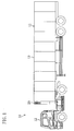
- a refrigerated vehicle (10) of this embodiment includes a trailer (11) and a tractor (12) for towing the trailer (11) and is used to transport refrigerated food products, such as frozen food products or perishable food products, by land.
- the trailer (11) includes a trailer body (13), i.e., a refrigerator, and a refrigeration unit (20) for a trailer, i.e., a refrigeration unit for a refrigerated vehicle.
- the refrigeration unit (20) is placed on the front end surface of the trailer body (13), i.e., the surface thereof near the tractor (12).
- the refrigeration unit (20) includes a sub-engine (30) forming a refrigerating engine, two compressors (40), a refrigeration circuit (70), an electric generator (50), a battery (51), and a standby motor (60) forming an auxiliary motor.
- the sub-engine (30) is provided separately from a driving engine and configured as an exclusive engine for driving the refrigeration unit (20) so that a belt (21) is wound around a pulley (31) fitted onto a drive shaft of the sub-engine (30).
- the compressors (40) are scroll compressors and configured as so-called open compressors so that pulleys (41) fitted onto respective drive shafts of the compressors (40) are coupled through the belt (21) to the pulley (31) of the sub-engine (30).
- the compressors (40) are mechanically coupled to the sub-engine (30) and driven by the torque of the sub-engine (30).
- the pulleys (41) or other components for the compressors (40) are provided with disconnecting mechanisms, such as clutches.
- the compressors (40) are disconnectably coupled to the sub-engine (30).
- a refrigerant pipe (71) for the refrigeration circuit (70) operable in a vapor compression refrigeration cycle is coupled to the compressors (40).
- the two compressors (40) are connected in parallel to the refrigeration circuit (70).
- the refrigeration circuit (70) includes a condenser, an expansion mechanism, and an evaporator.
- Refrigerant circulates in the following manner: Refrigerant discharged from the compressors (40) is condensed by the condenser, decompressed by the expansion mechanism, then evaporated by the evaporator, and returned to the compressors (40). The indoor air of the trailer body (13) is cooled by the evaporator, thereby cooling the interior of the trailer body (13).
- the refrigeration circuit (70) includes fans (72) for the condenser and evaporator.
- Fan motors (7a) are coupled to the fans (72).
- a pulley (52) fitted onto a drive shaft of the electric generator (50) is coupled through another belt (21) to the pulley (31) of the sub-engine (30).
- the electric generator (50) generates electric power by the torque of the sub-engine (30).
- the pulley (52) or any other component for the electric generator (50) is provided with a disconnecting mechanism, such as a clutch.
- the electric generator (50) is disconnectably coupled to the sub-engine (30).
- the battery (51) is connected to the electric generator (50) to store the power generated by the electric generator (50).
- the electric generator (50) is electrically wired to the fan motors (7a) so that the fan motors (7a) are driven by the electric power generated by the electric generator (50). Furthermore, the fan motors (7a) are electrically wired also to the battery (51) and selectively connected to the electric generator (50) and the battery (51) so as to be driven by at least one of the electric power from the electric generator (50) and the electric power from the battery (51).
- the fan motors (7a) are formed of alternating motors.
- the direct-current power supplied from the electric generator (50) and the battery (51) is converted into alternating-current power, and then the resultant alternating-current power is supplied to the fan motors (7a).
- the electric generator (50) and the battery (51) feed power also to control devices.
- the standby motor (60) is connectable to an external power source and permits a freezing operation of the refrigeration circuit (70) also during the period during which the refrigerated vehicle (10) is parked in a garage or the like.
- a pulley (61) fitted onto a drive shaft of the standby motor (60) is coupled through the associated belt (21) to the pulley (31) of the sub-engine (30) so as to be coupled to the compressors (40).
- the pulley (61) or any other component for the standby motor (60) is provided with a disconnecting mechanism, such as a clutch.
- the standby motor (60) is disconnectably coupled to the compressors (40).
- the standby motor (60) drives the compressors (40) during the stop period of the sub-engine (30) and is formed of a compact motor capable of rotating at high speed.
- a controller (90) is connected to the sub-engine (30) and provided with a rotational speed control unit (91) forming a rotational speed controller for the sub-engine (30).
- the rotational speed control unit (91) controls the rotational speed of the sub-engine (30).
- the rotational speed controller is configured, for example, to control a throttle motor for driving a throttle valve of the sub-engine (30).
- the rotational speed control unit (91) linearly controls fluctuations in the rotational speed of the sub-engine (30) such that the refrigeration capacity of the refrigeration unit grows or declines in response to the refrigeration load. More particularly, the rotational speed control unit (91) linearly increases the rotational speed of the sub-engine (30) on the basis of, for example, the temperature differential between an indoor temperature and a desired temperature in the following manner: With an increase in the temperature differential and an associated increase in the refrigeration load, the refrigeration capacity grows. Conversely, the rotational speed control unit (91) linearly decreases the rotational speed of the sub-engine (30), for example, in the following manner: With a decrease in the temperature differential between the indoor temperature and the desired temperature and an associated decrease in the refrigeration load, the refrigeration capacity declines.
- the rotation of the sub-engine (30) permits the rotational drive of the two compressors (40).
- the rotational drive of the compressors (40) allows the compressors (40) to compress refrigerant in the refrigeration circuit (70).
- the refrigerant circulates in the following manner: The refrigerant discharged from the compressors (40) is condensed by the condenser, decompressed by the expansion mechanism, then evaporated by the evaporator, and returned to the compressors (40).
- the indoor air of the trailer body (13) is cooled by the evaporator, thereby cooling the interior of the trailer body (13).
- the temperature of the indoor air of the trailer body (13) is sensed, thereby detecting the refrigeration load on the basis of the temperature differential between the indoor temperature and the desired temperature.
- the rotational speed control unit (91) linearly increases the rotational speed of the sub-engine (30) so that, with the increase in the temperature differential, the refrigeration capacity grows.
- the rotational speed control unit (91) linearly decreases the rotational speed of the sub-engine (30) so that, with the decrease in the temperature differential, the refrigeration capacity declines.
- the refrigeration capacity is controlled in the following manner: If the refrigeration load is small, only one of the two compressors (40) is driven, and if the refrigeration load is large, both of the two compressors (40) are driven.
- the rotation of the sub-engine (30) allows the electric generator (50) to generate electric power.
- the electric power of the electric generator (50) is supplied to the fan motors (7a), thereby driving the fans (72).
- the generated electric power of the electric generator (50) is fed also to control devices, such as the controller (90), and fed also to the battery (51) so as to be stored therein.
- the standby motor (60) On condition that a freezing operation of the refrigeration circuit (70) is performed also during the period during which the refrigerated vehicle (10) is parked in a garage or the like, the standby motor (60) is connected to an external power source. The drive of the standby motor (60) allows the torque of the standby motor (60) to drive the compressors (40). As a result, the refrigeration circuit (70) continues its cooling operation. In this case, while the coupling between the compressors (40) and the sub-engine (30) is interrupted, the standby motor (60) is coupled to the compressors (40).
- the refrigeration unit is equipped with the two compressors (40), the number of operating one or ones of the compressors (40) is controlled, thereby extensively adjusting the refrigeration capacity in response to the rotational speed range of the sub-engine (30). This adjustment allows the refrigeration capacity to adapt to extensive refrigeration loads.
- the electric power generated by the electric generator (50) drives the fan motors (7a). Therefore, the fan motors (7a) can form alternating motors, resulting in improved efficiency.
- the standby motor (60) since the standby motor (60) is provided, an operation of the refrigeration circuit (70) can be continued, for example, also during the stop period of the sub-engine (30). This can increase the range of use for the refrigeration unit.
- the above embodiment of the present invention may be configured as follows.
- the compressors (40) are always driven during the cooling operation.
- the rotation of the sub-engine (30) may be stopped, and only the fan motors (7a) may be driven by the electric power stored in the battery (51), thereby maintaining the indoor temperature only by an air blowing operation.
- the operating time of the sub-engine (30) can be reduced.
- the sub-engine (30) may be stopped, the electric power stored in the battery (51) may allow the electric generator (50) to develop torque, and the rotation of the electric generator (50) may drive the compressors (40).
- the electric generator (50) may double as a motor to drive the compressors (40).
- coupling between the compressors (40) and the sub-engine (30) is interrupted. Consequently, the sub-engine (30) can be used in its high-efficiency range, resulting in further energy savings.
- the rotational speed control unit (91) may be omitted. More particularly, the sub-engine (30) may be driven at a constant rotational speed. Meanwhile, according to the invention, if the refrigeration load is reduced, the sub-engine (30) is stopped, the electric power stored in the battery (51) allows the electric generator (50) to develop torque, and the rotation of the electric generator (50) drives the compressors (40). In this case, the power of the sub-engine (30) and the electric power of the battery (51) can be selectively used. This provides the refrigeration capacity matched with the refrigeration load while permitting energy savings, resulting in improved efficiency.
- the electric generator (50) and the standby motor (60) are both provided, the electric generator (50) may double as the standby motor (60). In other words, the electric generator (50) may be selectively connectable to an external power source and the battery (51). As a result, the number of components can be reduced.
- compressors (40) Although in the above embodiment the two compressors (40) are provided, a single compressor (40) may be provided in the present invention. Alternatively, three or more compressors (40) may be provided.
- the standby motor (60) is provided, it does not always need to be provided in the first, second and other aspects of the invention. In other words, the standby motor (60) may be provided as an optional item.
- the refrigerated vehicle (10) may be a refrigerated truck or any other refrigerated vehicle.
- the present invention is useful for refrigeration units for refrigerated vehicles for cooling, for example, the indoor air in the interior of a trailer body.
Landscapes
- Engineering & Computer Science (AREA)
- Physics & Mathematics (AREA)
- Thermal Sciences (AREA)
- Mechanical Engineering (AREA)
- Health & Medical Sciences (AREA)
- Public Health (AREA)
- Transportation (AREA)
- General Engineering & Computer Science (AREA)
- Devices That Are Associated With Refrigeration Equipment (AREA)
Claims (4)
- Kühlfahrzeug-Kühleinheit zum Kühlen des Inneren eines Kühlgeräts (13) eines Kühlfahrzeugs (10), wobei die Kühleinheit aufweist:eine Kältemaschine (30);einen Verdichter (40), der angeordnet ist, um durch die Kältemaschine (30) angetrieben zu werden; undeinen Kühlkreislauf (70), der mit dem Verdichter (40) verbunden ist und in einem Dampfverdichtungskältekreislauf betreibbar ist, wobeidie Kühlfahrzeug-Kühleinheit eine Batterie (51) zum Speichern von elektrischer Energie und einen elektrischen Generator (50) zum Erzeugen von elektrischer Energie durch die Drehbewegung der Kältemaschine (30) aufweist, um die erzeugte elektrische Energie in der Batterie (51) zu speichern, unddie Kältemaschine (30) trennbar mit dem Verdichter (40) verbunden ist, und der elektrische Generator (50) mit dem Verdichter (40) verbunden ist, dadurch gekennzeichnet, dassdie Kühlfahrzeug-Kühleinheit so angeordnet ist, dass, wenn eine Kühllast groß ist, der Verdichter (40) durch die Kältemaschine (30) angetrieben wird und die Rotation der Kältemaschine (30) es ermöglicht, dass der elektrische Generator (50) elektrische Energie erzeugt, und, wenn die Kühllast klein ist, die Kältemaschine (30) gestoppt wird und die elektrische Energie, welche in der Batterie (51) gespeichert ist, es ermöglicht, dass der elektrische Generator (50) Drehmoment entwickelt und die Rotation des elektrischen Generators (50) den Verdichter (40) antreibt.
- Kühlfahrzeug-Kühleinheit nach Anspruch 1, bei welcher
der Verdichter (40) eine Vielzahl von Verdichtern (40) aufweist, und die Vielzahl von Verdichtern (40) parallel geschaltet sind und mit dem Kühlkreislauf (70) verbunden sind. - Kühlfahrzeug-Kühleinheit nach Anspruch 1 oder 2 mit ferner
einem Hilfsmotor (60), welcher trennbar mit dem Verdichter (40) verbunden ist und durch elektrische Energie einer externen Energiequelle angetrieben wird. - Kühlfahrzeug-Kühleinheit nach Anspruch 3, bei welcher
der elektrische Generator (50) selektiv mit einer externen Energiequelle und der Batterie (51) verbindbar ist.
Applications Claiming Priority (2)
| Application Number | Priority Date | Filing Date | Title |
|---|---|---|---|
| JP2007016342A JP4325678B2 (ja) | 2007-01-26 | 2007-01-26 | 冷凍車両用冷凍装置 |
| PCT/JP2008/050975 WO2008090949A1 (ja) | 2007-01-26 | 2008-01-24 | 冷凍車両用冷凍装置 |
Publications (3)
| Publication Number | Publication Date |
|---|---|
| EP2128545A1 EP2128545A1 (de) | 2009-12-02 |
| EP2128545A4 EP2128545A4 (de) | 2011-05-18 |
| EP2128545B1 true EP2128545B1 (de) | 2013-10-09 |
Family
ID=39644523
Family Applications (1)
| Application Number | Title | Priority Date | Filing Date |
|---|---|---|---|
| EP08703803.0A Not-in-force EP2128545B1 (de) | 2007-01-26 | 2008-01-24 | Kühlvorrichtung für kühlfahrzeug |
Country Status (6)
| Country | Link |
|---|---|
| US (1) | US20090314019A1 (de) |
| EP (1) | EP2128545B1 (de) |
| JP (1) | JP4325678B2 (de) |
| CN (1) | CN101583833B (de) |
| DK (1) | DK2128545T3 (de) |
| WO (1) | WO2008090949A1 (de) |
Families Citing this family (71)
| Publication number | Priority date | Publication date | Assignee | Title |
|---|---|---|---|---|
| DE202008002920U1 (de) * | 2008-02-29 | 2008-05-29 | GM Global Technology Operations, Inc., Detroit | Temperierbares Ladestaufach |
| JP5404138B2 (ja) * | 2009-03-31 | 2014-01-29 | 三菱重工業株式会社 | エンジン駆動式冷凍装置 |
| US9557100B2 (en) * | 2009-10-27 | 2017-01-31 | Carrier Corporation | Hybrid refrigeration system for a mobile unit and method of operation |
| US8590330B2 (en) | 2010-06-03 | 2013-11-26 | Thermo King Corporation | Electric transport refrigeration unit with temperature-based diesel operation |
| CN101898500B (zh) * | 2010-07-19 | 2011-12-07 | 浙江博阳压缩机有限公司 | 直流电驱动移动制冷设备 |
| KR101038671B1 (ko) * | 2010-12-10 | 2011-06-02 | 고홍달 | 냉동차량용 냉각장치 |
| US8536834B2 (en) * | 2010-12-23 | 2013-09-17 | Thermo King Corporation | Mobile environment-controlled unit and method of operating a mobile environment-controlled unit |
| US9132735B2 (en) * | 2011-02-17 | 2015-09-15 | George Black | Electric car systems |
| US8720618B1 (en) | 2011-03-28 | 2014-05-13 | Aura Systems Inc. | Retrofitting a vehicle to transfer mechanical power out of an engine compartment |
| BR112013025808A2 (pt) * | 2011-04-04 | 2016-12-20 | Carrier Corp | método para operar um sistema de refrigeração, e, sistema de refrigeração de transportes |
| WO2012138497A1 (en) * | 2011-04-04 | 2012-10-11 | Carrier Corporation | Semi-electric mobile refrigerated system |
| CN102226462B (zh) * | 2011-04-14 | 2013-05-08 | 福州金飞鱼柴油机有限公司 | 一台发动机与多台车用空调压缩机的变速直连装置 |
| CN102310746A (zh) * | 2011-06-10 | 2012-01-11 | 合肥工业大学 | 一种冷藏车用电动制冷机组 |
| EP2764301B1 (de) | 2011-09-23 | 2019-11-27 | Carrier Corporation | Transportkühlsystem mit motorabgaskühlung |
| WO2013095889A2 (en) * | 2011-12-20 | 2013-06-27 | Carrier Corporation | Transport refrigeration system with engine shaft horsepower augmentation |
| GB201200735D0 (en) * | 2012-01-17 | 2012-02-29 | G A H Refrigeration Poducts Ltd | Secondary alternator for a power system |
| US9562715B2 (en) * | 2012-03-21 | 2017-02-07 | Thermo King Corporation | Power regulation system for a mobile environment-controlled unit and method of controlling the same |
| FR2993506B1 (fr) * | 2012-07-19 | 2015-06-05 | Leroy Somer Moteurs | Ensemble comportant un generateur et des moteurs electriques, pour un systeme de climatisation ou de refrigeration de vehicule. |
| FR2993505B1 (fr) * | 2012-07-19 | 2015-06-26 | Leroy Somer Moteurs | Ensemble comportant un generateur et des moteurs electrique, pour un systeme de climatisation ou de refrigeration de vehicule. |
| CN102837634B (zh) * | 2012-09-27 | 2015-01-21 | 郑州凯雪冷链股份有限公司 | 具有三温区的车载冷藏车厢 |
| US8764469B2 (en) | 2012-09-28 | 2014-07-01 | Atlantic Great Dane, Inc. | Power supply system including panel with safety release |
| US9093788B2 (en) | 2012-09-28 | 2015-07-28 | Atlantic Great Dane, Inc. | Power supply system including panel with safety release |
| CN104684758B (zh) | 2012-10-08 | 2018-03-23 | 冷王公司 | 用于为运输制冷系统提供动力的系统和方法 |
| WO2014082069A1 (en) * | 2012-11-26 | 2014-05-30 | Thermo King Corporation | Auxiliary subcooling circuit for a transport refrigeration system |
| US9010140B2 (en) * | 2013-02-15 | 2015-04-21 | City of Tallahassee | Vehicle idle time reduction system and method |
| US20140250932A1 (en) * | 2013-03-05 | 2014-09-11 | Valdemar A. Martinez, JR. | Portable heat exchange cooler |
| US20140283533A1 (en) * | 2013-03-22 | 2014-09-25 | Aura Systems, Inc. | Apparatus and Method for Electrical Transport Refrigeration in a Tractor-Trailer System |
| GB2513944B (en) * | 2014-01-29 | 2015-04-08 | Perpetual V2G Systems Ltd | Improvements in and relating to a vehicular refrigerator system |
| SG11201803311VA (en) * | 2015-11-09 | 2018-05-30 | Carrier Corp | Parallel loop intermodal container |
| US10823476B2 (en) | 2016-04-05 | 2020-11-03 | Carrier Corporation | Engineless transport refrigeration unit |
| CN107839438B (zh) * | 2016-09-21 | 2019-11-22 | 比亚迪股份有限公司 | 双驱压缩机切换控制方法、控制装置、控制系统以及车辆 |
| CN106627326A (zh) * | 2016-11-04 | 2017-05-10 | 无锡市普欧电子有限公司 | 一种具有备电系统的冷藏车空调系统 |
| CN106739961A (zh) * | 2016-12-31 | 2017-05-31 | 重庆樽明汽车零部件有限公司 | 一种货车保温系统 |
| WO2018136738A2 (en) | 2017-01-20 | 2018-07-26 | Carrier Corporation | Transport refrigeration unit (tru) direct current (dc) architecture |
| EP3692315B8 (de) * | 2017-10-05 | 2024-07-03 | Carrier Corporation | Mehrleistungswandlereinheit für eine anhängerkühleinheit |
| CN108167072A (zh) * | 2017-11-21 | 2018-06-15 | 重庆智仁发电设备有限责任公司 | 冷链车用发电机组 |
| FR3076492B1 (fr) * | 2018-01-09 | 2020-01-10 | Moteurs Leroy-Somer | Ensemble comportant un generateur et des moteurs electriques, pour un systeme de climatisation ou de refrigeration de vehicule |
| EP3626489A1 (de) | 2018-09-19 | 2020-03-25 | Thermo King Corporation | Verfahren und systeme zur energieverwaltung einer klimaanlage für transportfahrzeuge |
| EP3626490A1 (de) | 2018-09-19 | 2020-03-25 | Thermo King Corporation | Verfahren und systeme zur leistungs- und lastverwaltung einer klimaanlage für den transport |
| US11932076B2 (en) | 2018-09-28 | 2024-03-19 | Carrier Corporation | Transportation refrigeration unit with external AC generator power source |
| WO2020068502A1 (en) | 2018-09-28 | 2020-04-02 | Carrier Corporation | Transportation refrigeration unit with external dc generator power source |
| WO2020068641A1 (en) | 2018-09-28 | 2020-04-02 | Carrier Corporation | Simultaneous charge/discharge of battery for transportation refrigeration usage |
| US11945284B2 (en) | 2018-09-28 | 2024-04-02 | Carrier Corporation | Transportation refrigeration unit with DC generator charging of prime mover energy storage device |
| CN112313101B (zh) | 2018-09-28 | 2023-09-01 | 开利公司 | 带有能量存储系统和外部dc电力来源的运输制冷单元 |
| US11034213B2 (en) | 2018-09-29 | 2021-06-15 | Thermo King Corporation | Methods and systems for monitoring and displaying energy use and energy cost of a transport vehicle climate control system or a fleet of transport vehicle climate control systems |
| US11273684B2 (en) | 2018-09-29 | 2022-03-15 | Thermo King Corporation | Methods and systems for autonomous climate control optimization of a transport vehicle |
| US10875497B2 (en) | 2018-10-31 | 2020-12-29 | Thermo King Corporation | Drive off protection system and method for preventing drive off |
| US10926610B2 (en) | 2018-10-31 | 2021-02-23 | Thermo King Corporation | Methods and systems for controlling a mild hybrid system that powers a transport climate control system |
| US11059352B2 (en) | 2018-10-31 | 2021-07-13 | Thermo King Corporation | Methods and systems for augmenting a vehicle powered transport climate control system |
| US10870333B2 (en) | 2018-10-31 | 2020-12-22 | Thermo King Corporation | Reconfigurable utility power input with passive voltage booster |
| US11022451B2 (en) | 2018-11-01 | 2021-06-01 | Thermo King Corporation | Methods and systems for generation and utilization of supplemental stored energy for use in transport climate control |
| US11554638B2 (en) | 2018-12-28 | 2023-01-17 | Thermo King Llc | Methods and systems for preserving autonomous operation of a transport climate control system |
| EP3906175A1 (de) | 2018-12-31 | 2021-11-10 | Thermo King Corporation | Verfahren und systeme zur bereitstellung von prädiktiver energieverbrauchsrückkopplung zur speisung eines transportklimaregelungssystems unter verwendung externer daten |
| WO2020142063A1 (en) | 2018-12-31 | 2020-07-09 | Thermo King Corporation | Methods and systems for providing predictive energy consumption feedback for powering a transport climate control system |
| ES2982673T3 (es) | 2018-12-31 | 2024-10-17 | Thermo King Llc | Métodos y sistemas para notificar y mitigar un evento subóptimo que se produce en un sistema de control de climatización de transporte |
| US11072321B2 (en) | 2018-12-31 | 2021-07-27 | Thermo King Corporation | Systems and methods for smart load shedding of a transport vehicle while in transit |
| EP3906174B1 (de) | 2018-12-31 | 2024-05-29 | Thermo King LLC | Verfahren und systemen zur feststellung eines feedbacks für die klimasteuerung eines transportmittels |
| JP7274950B2 (ja) * | 2019-06-14 | 2023-05-17 | 三菱重工サーマルシステムズ株式会社 | 冷凍システム |
| ES2965029T3 (es) | 2019-06-28 | 2024-04-10 | Thermo King Llc | Vehículo climatizado, equipo de control climático para el transporte, método de readaptación de un vehículo y método de funcionamiento |
| EP3771814B1 (de) * | 2019-07-29 | 2023-10-04 | Thermo King LLC | Steuerungssystem und verfahren für einen elektronisch gesteuerten motor eines kühlsystems |
| US11376922B2 (en) | 2019-09-09 | 2022-07-05 | Thermo King Corporation | Transport climate control system with a self-configuring matrix power converter |
| US11458802B2 (en) | 2019-09-09 | 2022-10-04 | Thermo King Corporation | Optimized power management for a transport climate control energy source |
| US10985511B2 (en) | 2019-09-09 | 2021-04-20 | Thermo King Corporation | Optimized power cord for transferring power to a transport climate control system |
| ES2992855T3 (en) | 2019-09-09 | 2024-12-19 | Thermo King Llc | Prioritized power delivery for facilitating transport climate control |
| US11203262B2 (en) | 2019-09-09 | 2021-12-21 | Thermo King Corporation | Transport climate control system with an accessory power distribution unit for managing transport climate control loads |
| US11135894B2 (en) | 2019-09-09 | 2021-10-05 | Thermo King Corporation | System and method for managing power and efficiently sourcing a variable voltage for a transport climate control system |
| US11420495B2 (en) | 2019-09-09 | 2022-08-23 | Thermo King Corporation | Interface system for connecting a vehicle and a transport climate control system |
| US11214118B2 (en) | 2019-09-09 | 2022-01-04 | Thermo King Corporation | Demand-side power distribution management for a plurality of transport climate control systems |
| US11794551B2 (en) | 2019-09-09 | 2023-10-24 | Thermo King Llc | Optimized power distribution to transport climate control systems amongst one or more electric supply equipment stations |
| US11489431B2 (en) | 2019-12-30 | 2022-11-01 | Thermo King Corporation | Transport climate control system power architecture |
| CN116696580A (zh) * | 2023-06-08 | 2023-09-05 | 一汽解放汽车有限公司 | 冷藏车的发动机转速控制方法、控制装置及冷藏车 |
Family Cites Families (21)
| Publication number | Priority date | Publication date | Assignee | Title |
|---|---|---|---|---|
| US3844130A (en) * | 1973-07-09 | 1974-10-29 | M Wahnish | Automobile air conditioning system employing auxiliary prime motor |
| JPH0538933A (ja) * | 1991-08-08 | 1993-02-19 | Mitsubishi Heavy Ind Ltd | 陸上輸送用冷凍装置 |
| JPH08105666A (ja) * | 1994-08-08 | 1996-04-23 | Mitsubishi Heavy Ind Ltd | 輸送用冷凍装置 |
| JP2000257553A (ja) * | 1999-03-09 | 2000-09-19 | Seiko Seiki Co Ltd | マルチコンプレッサの動力伝達機構 |
| US6233957B1 (en) * | 1999-06-07 | 2001-05-22 | Mitsubishi Heavy Industries, Ltd. | Vehicular air conditioner |
| JP4426737B2 (ja) * | 2000-06-28 | 2010-03-03 | 東芝キヤリア株式会社 | 車両用冷凍装置 |
| JP2002081821A (ja) * | 2000-08-31 | 2002-03-22 | Mitsubishi Heavy Ind Ltd | 車載用冷凍装置 |
| US6745585B2 (en) * | 2000-12-26 | 2004-06-08 | Visteon Global Technologies, Inc. | Electric air conditioner sustain system |
| JP2002205538A (ja) * | 2001-01-09 | 2002-07-23 | Toyota Industries Corp | 車両用空調システム |
| US6434960B1 (en) * | 2001-07-02 | 2002-08-20 | Carrier Corporation | Variable speed drive chiller system |
| JP3854119B2 (ja) * | 2001-10-09 | 2006-12-06 | 株式会社デンソー | 圧縮機制御装置 |
| JP4114420B2 (ja) * | 2002-07-12 | 2008-07-09 | 株式会社デンソー | ハイブリッドコンプレッサ及びその制御装置 |
| ATE433557T1 (de) * | 2002-09-13 | 2009-06-15 | Whirlpool Co | Verfahren zum steuern eines kühlschrankes mit mehreren kühlfächern und ein solches verfahren verwendender kühlschrank |
| US6763668B1 (en) * | 2003-05-05 | 2004-07-20 | Carrier Corporation | Unibody modular bus air conditioner |
| TWI309290B (en) * | 2003-05-30 | 2009-05-01 | Sanyo Electric Co | Cooling apparatus |
| DE102004002386A1 (de) * | 2003-06-06 | 2005-08-11 | Enginion Ag | Antriebsanordnung für Hilfsaggregate |
| JP2005001523A (ja) * | 2003-06-12 | 2005-01-06 | Honda Motor Co Ltd | 車両用空調装置 |
| DE10355397A1 (de) * | 2003-11-25 | 2005-06-30 | Behr Gmbh & Co. Kg | Kraftfahrzeug-Klimaanlage mit Standklimatisierung |
| JP2006234198A (ja) * | 2005-02-22 | 2006-09-07 | Mitsubishi Heavy Ind Ltd | 冷凍車用冷凍装置および冷凍車用冷凍庫 |
| US8136363B2 (en) * | 2005-04-15 | 2012-03-20 | Thermo King Corporation | Temperature control system and method of operating the same |
| US20090056354A1 (en) * | 2007-08-30 | 2009-03-05 | Scott Judson Davis | Refrigeration power system for a storage compartment in a vehicle |
-
2007
- 2007-01-26 JP JP2007016342A patent/JP4325678B2/ja not_active Expired - Fee Related
-
2008
- 2008-01-24 EP EP08703803.0A patent/EP2128545B1/de not_active Not-in-force
- 2008-01-24 DK DK08703803.0T patent/DK2128545T3/da active
- 2008-01-24 CN CN200880002617XA patent/CN101583833B/zh not_active Expired - Fee Related
- 2008-01-24 WO PCT/JP2008/050975 patent/WO2008090949A1/ja not_active Ceased
- 2008-01-24 US US12/524,369 patent/US20090314019A1/en not_active Abandoned
Also Published As
| Publication number | Publication date |
|---|---|
| EP2128545A4 (de) | 2011-05-18 |
| JP4325678B2 (ja) | 2009-09-02 |
| EP2128545A1 (de) | 2009-12-02 |
| JP2008185222A (ja) | 2008-08-14 |
| WO2008090949A1 (ja) | 2008-07-31 |
| CN101583833A (zh) | 2009-11-18 |
| CN101583833B (zh) | 2011-04-13 |
| US20090314019A1 (en) | 2009-12-24 |
| DK2128545T3 (da) | 2013-12-02 |
Similar Documents
| Publication | Publication Date | Title |
|---|---|---|
| EP2128545B1 (de) | Kühlvorrichtung für kühlfahrzeug | |
| EP2694304B1 (de) | Halbelektrisches mobiles gekühltes system | |
| EP2479515B1 (de) | Kühlsystem für container | |
| EP2668051B1 (de) | Effizienter steueralgorithmus für den start-stopp-betrieb einer motorbetriebenen kühleinheit | |
| EP2643177B1 (de) | Strombegrenzungssteuerung in einem transportkühlsystem | |
| US9982921B2 (en) | Cooling system for in-transit cooling | |
| US6830438B2 (en) | Hybrid compressor | |
| US6927500B2 (en) | Automotive accessories control system | |
| KR20050086188A (ko) | 엔진과 전기 모터로 구동되는 공기 조화기 및 이를제어하는 방법 | |
| KR102577070B1 (ko) | 냉동차량용 냉방 및 냉동장치의 설치구조 | |
| US20050074339A1 (en) | Hybrid compressor device | |
| KR20140087960A (ko) | 차량용 냉각장치 | |
| US10823484B2 (en) | Intelligent voltage control for electric heat and defrost in transport refrigeration system | |
| KR101038671B1 (ko) | 냉동차량용 냉각장치 | |
| CN110573811B (zh) | 制冷装置 | |
| EP1808317B1 (de) | Verfahren zur Steuerung einer Verdichterkupplung | |
| JP4745567B2 (ja) | 陸上輸送用冷凍装置及びその運転制御方法 | |
| JP2021196115A (ja) | 輸送用冷凍機械 | |
| JP2005225439A (ja) | 空調装置 | |
| JP5067306B2 (ja) | 車両の空調制御装置 | |
| JP2013002803A (ja) | トレーラ用冷凍装置 | |
| KR200160720Y1 (ko) | 에어컨의 냉매 액화장치 | |
| JPH02213678A (ja) | 車載用冷凍装置の運転制御方法 | |
| HK1164989B (en) | Truck trailer refrigeration system |
Legal Events
| Date | Code | Title | Description |
|---|---|---|---|
| PUAI | Public reference made under article 153(3) epc to a published international application that has entered the european phase |
Free format text: ORIGINAL CODE: 0009012 |
|
| 17P | Request for examination filed |
Effective date: 20090812 |
|
| AK | Designated contracting states |
Kind code of ref document: A1 Designated state(s): AT BE BG CH CY CZ DE DK EE ES FI FR GB GR HR HU IE IS IT LI LT LU LV MC MT NL NO PL PT RO SE SI SK TR |
|
| DAX | Request for extension of the european patent (deleted) | ||
| A4 | Supplementary search report drawn up and despatched |
Effective date: 20110418 |
|
| RIC1 | Information provided on ipc code assigned before grant |
Ipc: B60H 1/32 20060101ALI20110412BHEP Ipc: F25B 27/00 20060101AFI20080811BHEP Ipc: B60P 3/20 20060101ALI20110412BHEP |
|
| 17Q | First examination report despatched |
Effective date: 20111222 |
|
| REG | Reference to a national code |
Ref country code: DE Ref legal event code: R079 Ref document number: 602008027985 Country of ref document: DE Free format text: PREVIOUS MAIN CLASS: F25B0027000000 Ipc: F25D0029000000 |
|
| GRAP | Despatch of communication of intention to grant a patent |
Free format text: ORIGINAL CODE: EPIDOSNIGR1 |
|
| RIC1 | Information provided on ipc code assigned before grant |
Ipc: F25B 27/00 20060101ALI20130411BHEP Ipc: B60H 1/32 20060101ALI20130411BHEP Ipc: F25D 29/00 20060101AFI20130411BHEP Ipc: B60P 3/20 20060101ALI20130411BHEP |
|
| INTG | Intention to grant announced |
Effective date: 20130429 |
|
| GRAS | Grant fee paid |
Free format text: ORIGINAL CODE: EPIDOSNIGR3 |
|
| GRAA | (expected) grant |
Free format text: ORIGINAL CODE: 0009210 |
|
| AK | Designated contracting states |
Kind code of ref document: B1 Designated state(s): AT BE BG CH CY CZ DE DK EE ES FI FR GB GR HR HU IE IS IT LI LT LU LV MC MT NL NO PL PT RO SE SI SK TR |
|
| REG | Reference to a national code |
Ref country code: GB Ref legal event code: FG4D |
|
| REG | Reference to a national code |
Ref country code: AT Ref legal event code: REF Ref document number: 635741 Country of ref document: AT Kind code of ref document: T Effective date: 20131015 Ref country code: CH Ref legal event code: EP |
|
| REG | Reference to a national code |
Ref country code: IE Ref legal event code: FG4D |
|
| REG | Reference to a national code |
Ref country code: DK Ref legal event code: T3 Effective date: 20131128 |
|
| REG | Reference to a national code |
Ref country code: DE Ref legal event code: R096 Ref document number: 602008027985 Country of ref document: DE Effective date: 20131205 |
|
| REG | Reference to a national code |
Ref country code: AT Ref legal event code: MK05 Ref document number: 635741 Country of ref document: AT Kind code of ref document: T Effective date: 20131009 |
|
| REG | Reference to a national code |
Ref country code: NL Ref legal event code: VDEP Effective date: 20131009 |
|
| PG25 | Lapsed in a contracting state [announced via postgrant information from national office to epo] |
Ref country code: SI Free format text: LAPSE BECAUSE OF FAILURE TO SUBMIT A TRANSLATION OF THE DESCRIPTION OR TO PAY THE FEE WITHIN THE PRESCRIBED TIME-LIMIT Effective date: 20131009 |
|
| REG | Reference to a national code |
Ref country code: LT Ref legal event code: MG4D |
|
| PG25 | Lapsed in a contracting state [announced via postgrant information from national office to epo] |
Ref country code: HR Free format text: LAPSE BECAUSE OF FAILURE TO SUBMIT A TRANSLATION OF THE DESCRIPTION OR TO PAY THE FEE WITHIN THE PRESCRIBED TIME-LIMIT Effective date: 20131009 Ref country code: BE Free format text: LAPSE BECAUSE OF FAILURE TO SUBMIT A TRANSLATION OF THE DESCRIPTION OR TO PAY THE FEE WITHIN THE PRESCRIBED TIME-LIMIT Effective date: 20131009 Ref country code: FI Free format text: LAPSE BECAUSE OF FAILURE TO SUBMIT A TRANSLATION OF THE DESCRIPTION OR TO PAY THE FEE WITHIN THE PRESCRIBED TIME-LIMIT Effective date: 20131009 Ref country code: LT Free format text: LAPSE BECAUSE OF FAILURE TO SUBMIT A TRANSLATION OF THE DESCRIPTION OR TO PAY THE FEE WITHIN THE PRESCRIBED TIME-LIMIT Effective date: 20131009 Ref country code: NO Free format text: LAPSE BECAUSE OF FAILURE TO SUBMIT A TRANSLATION OF THE DESCRIPTION OR TO PAY THE FEE WITHIN THE PRESCRIBED TIME-LIMIT Effective date: 20140109 Ref country code: SE Free format text: LAPSE BECAUSE OF FAILURE TO SUBMIT A TRANSLATION OF THE DESCRIPTION OR TO PAY THE FEE WITHIN THE PRESCRIBED TIME-LIMIT Effective date: 20131009 Ref country code: IS Free format text: LAPSE BECAUSE OF FAILURE TO SUBMIT A TRANSLATION OF THE DESCRIPTION OR TO PAY THE FEE WITHIN THE PRESCRIBED TIME-LIMIT Effective date: 20140209 Ref country code: NL Free format text: LAPSE BECAUSE OF FAILURE TO SUBMIT A TRANSLATION OF THE DESCRIPTION OR TO PAY THE FEE WITHIN THE PRESCRIBED TIME-LIMIT Effective date: 20131009 |
|
| PG25 | Lapsed in a contracting state [announced via postgrant information from national office to epo] |
Ref country code: ES Free format text: LAPSE BECAUSE OF FAILURE TO SUBMIT A TRANSLATION OF THE DESCRIPTION OR TO PAY THE FEE WITHIN THE PRESCRIBED TIME-LIMIT Effective date: 20131009 Ref country code: PL Free format text: LAPSE BECAUSE OF FAILURE TO SUBMIT A TRANSLATION OF THE DESCRIPTION OR TO PAY THE FEE WITHIN THE PRESCRIBED TIME-LIMIT Effective date: 20131009 Ref country code: CY Free format text: LAPSE BECAUSE OF FAILURE TO SUBMIT A TRANSLATION OF THE DESCRIPTION OR TO PAY THE FEE WITHIN THE PRESCRIBED TIME-LIMIT Effective date: 20131009 Ref country code: AT Free format text: LAPSE BECAUSE OF FAILURE TO SUBMIT A TRANSLATION OF THE DESCRIPTION OR TO PAY THE FEE WITHIN THE PRESCRIBED TIME-LIMIT Effective date: 20131009 Ref country code: LV Free format text: LAPSE BECAUSE OF FAILURE TO SUBMIT A TRANSLATION OF THE DESCRIPTION OR TO PAY THE FEE WITHIN THE PRESCRIBED TIME-LIMIT Effective date: 20131009 |
|
| PG25 | Lapsed in a contracting state [announced via postgrant information from national office to epo] |
Ref country code: PT Free format text: LAPSE BECAUSE OF FAILURE TO SUBMIT A TRANSLATION OF THE DESCRIPTION OR TO PAY THE FEE WITHIN THE PRESCRIBED TIME-LIMIT Effective date: 20140210 |
|
| REG | Reference to a national code |
Ref country code: DE Ref legal event code: R097 Ref document number: 602008027985 Country of ref document: DE |
|
| PG25 | Lapsed in a contracting state [announced via postgrant information from national office to epo] |
Ref country code: EE Free format text: LAPSE BECAUSE OF FAILURE TO SUBMIT A TRANSLATION OF THE DESCRIPTION OR TO PAY THE FEE WITHIN THE PRESCRIBED TIME-LIMIT Effective date: 20131009 |
|
| PLBE | No opposition filed within time limit |
Free format text: ORIGINAL CODE: 0009261 |
|
| STAA | Information on the status of an ep patent application or granted ep patent |
Free format text: STATUS: NO OPPOSITION FILED WITHIN TIME LIMIT |
|
| PG25 | Lapsed in a contracting state [announced via postgrant information from national office to epo] |
Ref country code: MC Free format text: LAPSE BECAUSE OF FAILURE TO SUBMIT A TRANSLATION OF THE DESCRIPTION OR TO PAY THE FEE WITHIN THE PRESCRIBED TIME-LIMIT Effective date: 20131009 Ref country code: LU Free format text: LAPSE BECAUSE OF FAILURE TO SUBMIT A TRANSLATION OF THE DESCRIPTION OR TO PAY THE FEE WITHIN THE PRESCRIBED TIME-LIMIT Effective date: 20140124 Ref country code: RO Free format text: LAPSE BECAUSE OF FAILURE TO SUBMIT A TRANSLATION OF THE DESCRIPTION OR TO PAY THE FEE WITHIN THE PRESCRIBED TIME-LIMIT Effective date: 20131009 Ref country code: CZ Free format text: LAPSE BECAUSE OF FAILURE TO SUBMIT A TRANSLATION OF THE DESCRIPTION OR TO PAY THE FEE WITHIN THE PRESCRIBED TIME-LIMIT Effective date: 20131009 Ref country code: SK Free format text: LAPSE BECAUSE OF FAILURE TO SUBMIT A TRANSLATION OF THE DESCRIPTION OR TO PAY THE FEE WITHIN THE PRESCRIBED TIME-LIMIT Effective date: 20131009 |
|
| REG | Reference to a national code |
Ref country code: CH Ref legal event code: PL |
|
| 26N | No opposition filed |
Effective date: 20140710 |
|
| GBPC | Gb: european patent ceased through non-payment of renewal fee |
Effective date: 20140124 |
|
| REG | Reference to a national code |
Ref country code: DE Ref legal event code: R097 Ref document number: 602008027985 Country of ref document: DE Effective date: 20140710 |
|
| PG25 | Lapsed in a contracting state [announced via postgrant information from national office to epo] |
Ref country code: CH Free format text: LAPSE BECAUSE OF NON-PAYMENT OF DUE FEES Effective date: 20140131 Ref country code: LI Free format text: LAPSE BECAUSE OF NON-PAYMENT OF DUE FEES Effective date: 20140131 |
|
| REG | Reference to a national code |
Ref country code: IE Ref legal event code: MM4A |
|
| PG25 | Lapsed in a contracting state [announced via postgrant information from national office to epo] |
Ref country code: GB Free format text: LAPSE BECAUSE OF NON-PAYMENT OF DUE FEES Effective date: 20140124 |
|
| PG25 | Lapsed in a contracting state [announced via postgrant information from national office to epo] |
Ref country code: IE Free format text: LAPSE BECAUSE OF NON-PAYMENT OF DUE FEES Effective date: 20140124 |
|
| REG | Reference to a national code |
Ref country code: FR Ref legal event code: PLFP Year of fee payment: 9 |
|
| PG25 | Lapsed in a contracting state [announced via postgrant information from national office to epo] |
Ref country code: MT Free format text: LAPSE BECAUSE OF FAILURE TO SUBMIT A TRANSLATION OF THE DESCRIPTION OR TO PAY THE FEE WITHIN THE PRESCRIBED TIME-LIMIT Effective date: 20131009 |
|
| PG25 | Lapsed in a contracting state [announced via postgrant information from national office to epo] |
Ref country code: BG Free format text: LAPSE BECAUSE OF FAILURE TO SUBMIT A TRANSLATION OF THE DESCRIPTION OR TO PAY THE FEE WITHIN THE PRESCRIBED TIME-LIMIT Effective date: 20131009 |
|
| PG25 | Lapsed in a contracting state [announced via postgrant information from national office to epo] |
Ref country code: GR Free format text: LAPSE BECAUSE OF FAILURE TO SUBMIT A TRANSLATION OF THE DESCRIPTION OR TO PAY THE FEE WITHIN THE PRESCRIBED TIME-LIMIT Effective date: 20140110 |
|
| PG25 | Lapsed in a contracting state [announced via postgrant information from national office to epo] |
Ref country code: TR Free format text: LAPSE BECAUSE OF FAILURE TO SUBMIT A TRANSLATION OF THE DESCRIPTION OR TO PAY THE FEE WITHIN THE PRESCRIBED TIME-LIMIT Effective date: 20131009 Ref country code: HU Free format text: LAPSE BECAUSE OF FAILURE TO SUBMIT A TRANSLATION OF THE DESCRIPTION OR TO PAY THE FEE WITHIN THE PRESCRIBED TIME-LIMIT; INVALID AB INITIO Effective date: 20080124 |
|
| REG | Reference to a national code |
Ref country code: FR Ref legal event code: PLFP Year of fee payment: 10 |
|
| REG | Reference to a national code |
Ref country code: FR Ref legal event code: PLFP Year of fee payment: 11 |
|
| PGFP | Annual fee paid to national office [announced via postgrant information from national office to epo] |
Ref country code: FR Payment date: 20221208 Year of fee payment: 16 |
|
| PGFP | Annual fee paid to national office [announced via postgrant information from national office to epo] |
Ref country code: DK Payment date: 20230111 Year of fee payment: 16 |
|
| PGFP | Annual fee paid to national office [announced via postgrant information from national office to epo] |
Ref country code: IT Payment date: 20221213 Year of fee payment: 16 Ref country code: DE Payment date: 20221130 Year of fee payment: 16 |
|
| P01 | Opt-out of the competence of the unified patent court (upc) registered |
Effective date: 20230525 |
|
| REG | Reference to a national code |
Ref country code: DE Ref legal event code: R119 Ref document number: 602008027985 Country of ref document: DE |
|
| REG | Reference to a national code |
Ref country code: DK Ref legal event code: EBP Effective date: 20240131 |
|
| PG25 | Lapsed in a contracting state [announced via postgrant information from national office to epo] |
Ref country code: DE Free format text: LAPSE BECAUSE OF NON-PAYMENT OF DUE FEES Effective date: 20240801 |
|
| PG25 | Lapsed in a contracting state [announced via postgrant information from national office to epo] |
Ref country code: FR Free format text: LAPSE BECAUSE OF NON-PAYMENT OF DUE FEES Effective date: 20240131 |
|
| PG25 | Lapsed in a contracting state [announced via postgrant information from national office to epo] |
Ref country code: FR Free format text: LAPSE BECAUSE OF NON-PAYMENT OF DUE FEES Effective date: 20240131 Ref country code: DE Free format text: LAPSE BECAUSE OF NON-PAYMENT OF DUE FEES Effective date: 20240801 |
|
| PG25 | Lapsed in a contracting state [announced via postgrant information from national office to epo] |
Ref country code: DK Free format text: LAPSE BECAUSE OF NON-PAYMENT OF DUE FEES Effective date: 20240131 |
|
| PG25 | Lapsed in a contracting state [announced via postgrant information from national office to epo] |
Ref country code: DK Free format text: LAPSE BECAUSE OF NON-PAYMENT OF DUE FEES Effective date: 20240131 |
|
| PG25 | Lapsed in a contracting state [announced via postgrant information from national office to epo] |
Ref country code: IT Free format text: LAPSE BECAUSE OF NON-PAYMENT OF DUE FEES Effective date: 20240124 |