EP2130972A2 - Installation destinée à transporter des personnes d'une station de montagne vers une station de vallée - Google Patents
Installation destinée à transporter des personnes d'une station de montagne vers une station de vallée Download PDFInfo
- Publication number
- EP2130972A2 EP2130972A2 EP09450097A EP09450097A EP2130972A2 EP 2130972 A2 EP2130972 A2 EP 2130972A2 EP 09450097 A EP09450097 A EP 09450097A EP 09450097 A EP09450097 A EP 09450097A EP 2130972 A2 EP2130972 A2 EP 2130972A2
- Authority
- EP
- European Patent Office
- Prior art keywords
- rails
- sub
- joint
- installation according
- region
- Prior art date
- Legal status (The legal status is an assumption and is not a legal conclusion. Google has not performed a legal analysis and makes no representation as to the accuracy of the status listed.)
- Withdrawn
Links
- 238000009434 installation Methods 0.000 claims abstract description 15
- 238000013016 damping Methods 0.000 claims description 9
- 239000000725 suspension Substances 0.000 description 5
- 230000035939 shock Effects 0.000 description 2
- 230000007704 transition Effects 0.000 description 2
- 238000006563 Carroll rearrangement reaction Methods 0.000 description 1
- 238000013459 approach Methods 0.000 description 1
- 238000005452 bending Methods 0.000 description 1
- 230000005540 biological transmission Effects 0.000 description 1
- 238000006073 displacement reaction Methods 0.000 description 1
- 230000005484 gravity Effects 0.000 description 1
- 230000003068 static effect Effects 0.000 description 1
Images




Classifications
-
- E—FIXED CONSTRUCTIONS
- E01—CONSTRUCTION OF ROADS, RAILWAYS, OR BRIDGES
- E01B—PERMANENT WAY; PERMANENT-WAY TOOLS; MACHINES FOR MAKING RAILWAYS OF ALL KINDS
- E01B25/00—Tracks for special kinds of railways
- E01B25/22—Tracks for railways with the vehicle suspended from rigid supporting rails
- E01B25/24—Supporting rails; Auxiliary balancing rails; Supports or connections for rails
-
- B—PERFORMING OPERATIONS; TRANSPORTING
- B61—RAILWAYS
- B61B—RAILWAY SYSTEMS; EQUIPMENT THEREFOR NOT OTHERWISE PROVIDED FOR
- B61B12/00—Component parts, details or accessories not provided for in groups B61B7/00 - B61B11/00
- B61B12/02—Suspension of the load; Guiding means, e.g. wheels; Attaching traction cables
Definitions
- the invention relates to a system for driving people from a mountain station in a valley station with a mounted on a suspension cable at a distance from the ground, consisting of a plurality of interconnected with partial rails rails rail along which carriages are movable.
- Such a plant is from the AT 410 306 B known.
- the speed of the car on the rail is occasionally 70 km / h or more, resulting in the joints connecting the rails and the transitions between the rails problems with the smoothness of the car and by the shocks occurring wear problems.
- the invention is therefore based on the object to avoid these problems as much as possible.
- the sub-rails are suspended in the inventive system of a rope, the sub-rails lower under the weight of occupied with one or more persons cars.
- this reduction is compensated by the fact that the partial rails are increased in the region of the joints by the extent of the expected reduction.
- partial rails are curved in a straight line or curve and to increase them in their initial and final regions by additional projections
- the partial rails it is preferred within the scope of the invention for the partial rails to be bent in such a way that their curvature causes the increase .
- Adjacent partial rails or their treads are thus inclined in the invention in the unloaded state at an angle not equal to 180 ° to each other.
- the extent of these angular deviations depends on several factors, e.g. The length of the sub-rails, the span of the rope between two supports, the sag of the rope, the weight of the car and the number of persons therein, etc.
- the angle, in the adjacent sub-rails or their treads in the joints are inclined to each other, between 175 ° and 179 °, preferably between 176 ° and 178 °. In individual cases, however, this angle can of course also be exceeded or fallen short of.
- a wedge-shaped gap is arranged at a joint between two sub-rails.
- the two sub-rails can be connected to each other via a hinge axis.
- This hinge axis can be arranged in the upper region, approximately at the middle level or in the lower region of the sub-rails.
- the hinge axis is arranged in the upper region and that the gap i loaded state of the joint is arranged below the hinge axis.
- the unloaded state of the joint thus no gap or only a small gap could be present, which then arises or increases when the sub-rails lower in the region of the joint when a car drives over it.
- the joint axis is arranged approximately at the middle height of the sub-rails and furthermore that the wedge-shaped gap is arranged above the joint axis in the unloaded state of the joint. This gap closes partially or completely when a car passes over the joint.
- a damping element is arranged on end faces of the partial rails in the region of the joints. If the joint axis is arranged approximately at mid-height of the sub-rails and the wedge-shaped gap is arranged in the unloaded state of the joint above the joint axis, the damping element is preferably arranged above the joint axis.
- the damping element may be arranged so that it constantly dampens the pivoting movement of the sub-rails or preferably so that it controls the movement the sub-rails only at the end of the lowering movement, ie just before the gap is completely closed or the sub-rails abut each other, is damped.
- the partial rails can be suspended from the cable in the region of the joints by means of the handlebars of track rest shoes.
- two partial rails connected to one another at the joint are suspended from a common rail support shoe in the region of a joint via a respective link.
- a rail support shoe has two or more optional bearings for a handlebar.
- This embodiment offers the further advantage that different loading conditions can be set in the power transmission between the interconnected at a joint rails and the rail support shoe by the possible different angles that can take the handlebar.
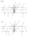
- Fig. 1 a section of a system for driving people from a mountain station in a valley station is shown, in which a running rail 1 is suspended from a support cable 2 via suspensions 3.
- the plant can in general as per se from the prior art, for example, the AT 410 306 B be known. That is, the support cable 2 is stretched between supports, fixed terrain points or the like, wherein a single support cable 2 or more, in the direction of travel successively arranged support cables 2 can be used.
- the rail 1 drive carriage not shown, which may take the form of cabins, armchairs, tubs or the like and in which persons or passengers sitting, lying or standing preferably ur driven by gravity from a mountain station to a valley station. Since the design of the mountain station and valley station, the supports or the like and the carriage for the invention are not of particular importance, they have not been shown in the drawings and are not described in detail in the description in the following.
- the running rail 1 consists of part rails 4, which are connected to joints 5 together.
- the sub-rails 4 are, as best in Fig. 2 can be seen bent so that they sag somewhat in their middle region or are increased in the region of the joints in relation to the middle region. The measure of this increase is in Fig. 2 denoted by X. If a car drives over a sub-rail 4 and is located in its central area, its weight is distributed approximately equally over both suspensions 3 at the beginning and at the end of the sub-rail 4 on the carrying cable 2.
- two adjacent sub-rails 4 abut one another at a hinge 5 at an angle ⁇ of less than 180 °, in the exemplary embodiment shown 177 °.
- This angle ⁇ is chosen such that, given the static and dynamic boundary conditions, such as e.g. the carrying capacity or elasticity of the supporting cable 2, the distance between two supports and the weight of a car, goes against 180 ° when the carriage drives over the hinge 5.
- a subsequent sub-rail 4 is then exactly in alignment with a preceding sub-rail 4, so that a bumpless overrunning of a joint 5 is made possible. This not only increases the comfort of the passengers considerably at higher driving speeds but also significantly reduces the wear on the sub-rails 4 and the joints 5 and the car.
- the sub-rails 4 have a continuous curvature over their entire length.
- the curvature can also be discontinuous, that is to say that the radius of curvature in the middle region is greater and becomes continuously or discontinuously smaller towards the ends of the partial rails 4.
- the sub-rails 4 are straight in the central region and curved towards the ends.
- the curvature which causes the inventive increase of the sub-rails 4, which compensates for the lowering when crossing the joints.
- the sub-rails 4 can additionally be curved in order to produce trajectories of the running rail 1.
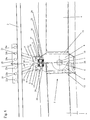
- a joint joint in the unloaded state is shown enlarged, are connected to the two sub-rails 4 at a joint 5 and suspended by a suspension 3 from the support cable 2.
- the joint 5, which in Fig. 5 shown in section on an enlarged scale is, has a hollow pin 6, which defines a hinge axis 7.
- the hollow pin 6 connects two joint parts 8 and 9, which are each connected to a rail part 4.
- the hollow pin 6 is secured by means of a securing bolt 10 against displacement and with the help of a rotation 11 against rotation.
- the joint parts 8 and 9 are received in circular cylindrical end caps 12, 13, which close the circular cylindrical tubes in the illustrated embodiment, which form the sub-rails 4.
- the outer circumference of the tubes forming the sub-rails 4 forms the running surface for the carriages, not shown in the drawings, which roll over rollers on these running surfaces.
- the outer diameter of the end caps 12, 13 is the same size as the outer diameter of the tubes forming the sub-rails 4, so that a shock-free driving over the joint 5 is possible.
- the rail support shoe 22 has in the illustrated embodiment, for each link 16, 17 each have three holes 23a, 23b, 23c and 24a, 24b, 24c, in which the hinge pin 20, 21 can be optionally used.
- the angle at which the links 16, 17 are aligned can be varied, whereby the power dissipation can be better adapted to the respective circumstances.
- the two joint parts 8, 9 and their projections 14,15 above the hinge axis 7 in the unloaded state by a wedge-shaped gap 25 are separated.
- the wedge angle ⁇ of this gap 25 is approximately the same as the angle 180 ° - ⁇ , in which the orientation of the ends of the sub-rails 4 and their treads deviates from the extended position.
- the damping elements 26 consist of pins 27 with widened heads 28, which are received in bores 29 in the lugs 15 and supported by disc springs 30 at the bottom of the holes 29.
- the heads 28 are only slightly above the end faces 31, 32 of the lugs 14, 15, so that the damping elements 26 are effective only shortly before the collision of the lugs 14, 15.
- the joint parts 8, 9 are also separated below the hinge axis 9 by a gap 35, which allows a free movement of the joints 5 also upwards. This is advantageous because the entire rail 1 can swing freely up and down during carriage of the car along the rail 1, without mechanically stressing the joints 5 in this way.
- additional rails 33, 34 are arranged, which on the one hand increase the flexural rigidity of the sub-rails 4 and on the other hand serve as guides for the drives of the car to a swinging of the car about the longitudinal axis of the sub-rails 4 limit or prevent.
Landscapes
- Engineering & Computer Science (AREA)
- Mechanical Engineering (AREA)
- Architecture (AREA)
- Civil Engineering (AREA)
- Structural Engineering (AREA)
- Transportation (AREA)
- Bridges Or Land Bridges (AREA)
- Platform Screen Doors And Railroad Systems (AREA)
- Leg Units, Guards, And Driving Tracks Of Cranes (AREA)
- Electric Cable Arrangement Between Relatively Moving Parts (AREA)
- Seats For Vehicles (AREA)
- Cage And Drive Apparatuses For Elevators (AREA)
- Toys (AREA)
Applications Claiming Priority (1)
| Application Number | Priority Date | Filing Date | Title |
|---|---|---|---|
| AT0088508A AT506915B1 (de) | 2008-06-02 | 2008-06-02 | Anlage zum abfahren von personen von einer bergstation in eine talstation |
Publications (2)
| Publication Number | Publication Date |
|---|---|
| EP2130972A2 true EP2130972A2 (fr) | 2009-12-09 |
| EP2130972A3 EP2130972A3 (fr) | 2013-01-09 |
Family
ID=40934556
Family Applications (1)
| Application Number | Title | Priority Date | Filing Date |
|---|---|---|---|
| EP09450097A Withdrawn EP2130972A3 (fr) | 2008-06-02 | 2009-05-07 | Installation destinée à transporter des personnes d'une station de montagne vers une station de vallée |
Country Status (12)
| Country | Link |
|---|---|
| US (1) | US8171857B2 (fr) |
| EP (1) | EP2130972A3 (fr) |
| JP (1) | JP5370998B2 (fr) |
| CN (1) | CN101596906B (fr) |
| AR (1) | AR071712A1 (fr) |
| AT (1) | AT506915B1 (fr) |
| AU (1) | AU2009202164A1 (fr) |
| BR (1) | BRPI0901761A2 (fr) |
| CA (1) | CA2666128C (fr) |
| NZ (1) | NZ577025A (fr) |
| RU (1) | RU2497700C2 (fr) |
| SA (1) | SA109300338B1 (fr) |
Families Citing this family (11)
| Publication number | Priority date | Publication date | Assignee | Title |
|---|---|---|---|---|
| AT506915B1 (de) * | 2008-06-02 | 2010-03-15 | Innova Patent Gmbh | Anlage zum abfahren von personen von einer bergstation in eine talstation |
| KR101566429B1 (ko) * | 2009-01-30 | 2015-11-06 | 삼성디스플레이 주식회사 | 표시판, 박막 트랜지스터 표시판 및 기판의 수리 방법 |
| US8863668B2 (en) * | 2010-03-19 | 2014-10-21 | Eco Adventure Technologies, Llc | Multidirectional transport system |
| US20140096699A1 (en) * | 2011-06-30 | 2014-04-10 | William J. Kitchen | Suspended Track Amusement Ride |
| US10099902B1 (en) * | 2015-10-07 | 2018-10-16 | The Boeing Company | Articulating rail for multidirectional movement of suspended load |
| US10220859B2 (en) * | 2015-10-28 | 2019-03-05 | Miracle Recreation Equipment Company | Zip line assembly and trolley therefore |
| US20190100220A1 (en) * | 2016-04-20 | 2019-04-04 | Tait Towers Manufacturing, LLC | A path following arrangement having a catenary structure and a method for operating such an arrangement |
| EP3329893B1 (fr) * | 2016-12-01 | 2020-09-23 | Liko Research & Development AB | Barrières de rails de levage |
| GB2569837B (en) * | 2018-07-31 | 2020-01-01 | Castree Projects Ltd | Zipline rail coupling |
| EP3636238B1 (fr) | 2018-10-12 | 2021-04-28 | Liko Research & Development AB | Barrières comportant des rampes de transition pour rails de levage |
| KR102479221B1 (ko) * | 2022-06-08 | 2022-12-20 | (주)신흥이앤지 | 익스트림 라이더용 주행레일 및 주행레일을 따라 이동하는 익스트림 라이더 |
Citations (1)
| Publication number | Priority date | Publication date | Assignee | Title |
|---|---|---|---|---|
| AT410306B (de) | 2001-03-07 | 2003-03-25 | Innova Patent Gmbh | Anlage zum abfahren von personen von einer bergstation in eine talstation |
Family Cites Families (24)
| Publication number | Priority date | Publication date | Assignee | Title |
|---|---|---|---|---|
| AT4103B (fr) | 1899-05-04 | 1901-05-10 | Arnold Kienast | |
| GB396374A (en) * | 1931-03-23 | 1933-08-03 | Adolf Bleichert & Co Ag | Improvements in and relating to ropeways |
| DE564329C (de) * | 1931-03-24 | 1932-11-17 | Bleichert Transportanlagen G M | Schwerlastseilbahn mit einer Laufbahn aus hintereinanderliegenden, miteinander verbundenen Abschnitten |
| GB642098A (en) * | 1945-06-15 | 1950-08-30 | Omnium Lyonnais | Improvements to systems including aerial trackways |
| DE1011447B (de) * | 1954-03-09 | 1957-07-04 | Wilhelm Grube | An Seilen, Gittertraegern od. dgl. Tragelementen geradlinig aufgehaengte Fahrbahn aus am Stoss unstarr verbundenen Fahrbahnabschnitten fuer ein- oder mehrspurige Haengebahnen |
| DE1238879B (de) | 1960-07-08 | 1967-04-20 | Willi Bayer Dipl Chem Dr | Klebereiter mit Beschriftungsstreifen |
| CH529645A (de) * | 1970-10-13 | 1972-10-31 | Mueller Gerhard | Seilbahnanordnung |
| BE790482A (fr) * | 1971-11-16 | 1973-02-15 | Patin Pierre | Transporteur du genre telepherique a cable porteur |
| CH611958A5 (fr) * | 1977-05-17 | 1979-06-29 | Rudolf Baltensperger | |
| DE2723543C2 (de) | 1977-05-25 | 1979-08-23 | Rudolf Hoeri Baltensperger | Schienenhängebahn-Anlage |
| DE2919318A1 (de) | 1977-05-25 | 1980-12-04 | Rudolf Baltensperger | Schienenhaengebahn-anlage |
| JPS60148302U (ja) * | 1984-03-08 | 1985-10-02 | 米山工業株式会社 | 懸垂式ラツクレ−ル |
| JPS6285501U (fr) * | 1985-11-14 | 1987-06-01 | ||
| GB8914169D0 (en) * | 1989-06-20 | 1989-08-09 | Latchways Ltd | Load attachment,transversing device |
| DE4310904A1 (de) * | 1993-04-02 | 1994-10-06 | Otto Ruppmann | Einschienen-Hängebahn mit einem insbesondere an mindestens einem Tragseil aufgehängten Fahrbalken |
| DE19533403C1 (de) * | 1995-09-09 | 1996-10-31 | Neuhaeuser Gmbh & Co | Gelenkige Schienenverbindung |
| NZ502388A (en) * | 1999-02-04 | 2000-03-27 | Konrad Dopplemayr & Sohn Masch | Installation for moving individuals from a mountain station into a valley station |
| AU2104101A (en) * | 1999-12-14 | 2001-06-25 | Yury Sherman | System for supporting substantially rigid linear structures |
| DE10056233A1 (de) * | 2000-03-13 | 2001-11-29 | Werner P Berwald | Kettenlose Aufhängung von EHB-Bahnen (Einschienen-Hänge-Bahnen) |
| AT409253B (de) * | 2000-07-20 | 2002-07-25 | Innova Patent Gmbh | Anlage zur beförderung von personen und verfahren zum betrieb einer derartigen anlage |
| AT409952B (de) | 2001-03-07 | 2002-12-27 | Innova Patent Gmbh | Anlage zum abfahren von personen von einer bergstation in eine talstation |
| EP1972365A3 (fr) * | 2007-03-22 | 2011-01-12 | Innova Patent GmbH | Installation destinée au transport de personnes |
| EP1980302A1 (fr) * | 2007-04-13 | 2008-10-15 | Philippe Perakis | Dispositif de suspension et de déplacement d'un objet ou d'une personne |
| AT506915B1 (de) * | 2008-06-02 | 2010-03-15 | Innova Patent Gmbh | Anlage zum abfahren von personen von einer bergstation in eine talstation |
-
2008
- 2008-06-02 AT AT0088508A patent/AT506915B1/de not_active IP Right Cessation
-
2009
- 2009-05-07 EP EP09450097A patent/EP2130972A3/fr not_active Withdrawn
- 2009-05-12 AR ARP090101703A patent/AR071712A1/es unknown
- 2009-05-14 JP JP2009117557A patent/JP5370998B2/ja not_active Expired - Fee Related
- 2009-05-15 NZ NZ577025A patent/NZ577025A/en unknown
- 2009-05-19 CA CA2666128A patent/CA2666128C/fr not_active Expired - Fee Related
- 2009-05-29 BR BRPI0901761-5A patent/BRPI0901761A2/pt not_active IP Right Cessation
- 2009-05-30 SA SA109300338A patent/SA109300338B1/ar unknown
- 2009-06-01 AU AU2009202164A patent/AU2009202164A1/en not_active Abandoned
- 2009-06-01 RU RU2009120739/11A patent/RU2497700C2/ru not_active IP Right Cessation
- 2009-06-02 CN CN200910143699.6A patent/CN101596906B/zh not_active Expired - Fee Related
- 2009-06-02 US US12/476,384 patent/US8171857B2/en not_active Expired - Fee Related
Patent Citations (1)
| Publication number | Priority date | Publication date | Assignee | Title |
|---|---|---|---|---|
| AT410306B (de) | 2001-03-07 | 2003-03-25 | Innova Patent Gmbh | Anlage zum abfahren von personen von einer bergstation in eine talstation |
Also Published As
| Publication number | Publication date |
|---|---|
| NZ577025A (en) | 2010-09-30 |
| CN101596906B (zh) | 2015-07-29 |
| AR071712A1 (es) | 2010-07-07 |
| BRPI0901761A2 (pt) | 2010-04-13 |
| CN101596906A (zh) | 2009-12-09 |
| AT506915A1 (de) | 2009-12-15 |
| JP2010001009A (ja) | 2010-01-07 |
| EP2130972A3 (fr) | 2013-01-09 |
| SA109300338B1 (ar) | 2013-12-10 |
| CA2666128C (fr) | 2014-02-25 |
| RU2009120739A (ru) | 2010-12-10 |
| US8171857B2 (en) | 2012-05-08 |
| RU2497700C2 (ru) | 2013-11-10 |
| US20090293757A1 (en) | 2009-12-03 |
| AU2009202164A1 (en) | 2009-12-17 |
| AT506915B1 (de) | 2010-03-15 |
| JP5370998B2 (ja) | 2013-12-18 |
| CA2666128A1 (fr) | 2009-12-02 |
Similar Documents
| Publication | Publication Date | Title |
|---|---|---|
| AT506915B1 (de) | Anlage zum abfahren von personen von einer bergstation in eine talstation | |
| EP3148916B1 (fr) | Chaîne articulée d'un trottoir roulant ou d'un escalier roulant | |
| EP1644239B1 (fr) | Bande de montage et/ou transporteuse courbe | |
| EP1086868B1 (fr) | Balancier à double effet pour supports de transporteurs aériens monocable, notamment de télésièges et de télécabines | |
| EP1640235B1 (fr) | Dispositif pour la fixation d'un élément mouvant d'une installation de téléphérique à une barre de suspension | |
| DE2636160A1 (de) | Endlosfoerderer | |
| EP2218662A2 (fr) | Transporteur à longerons mobiles | |
| WO2017064014A1 (fr) | Chariot de téléphérique | |
| EP1840072B1 (fr) | Grue dotée d'un bras et d'une bande de déroulement pour les chariots porte câbles | |
| DE3326103A1 (de) | Gelenkige stossverbindung fuer aufhaengbare schienen von einschienenhaengebahnen | |
| DE102012100791A1 (de) | Zugmittel-Windenvorrichtung | |
| DE3841660A1 (de) | Verfahren zum betreiben eines in einer kurve verlegten foerderbandes und kurvenbandfoerderer | |
| EP0327882A3 (fr) | Installation de téléphérage | |
| DE616758C (de) | Bandfoerderer mit biegsamem Foerderband | |
| DE10016121A1 (de) | Vorrichtung zur Speicherung von Fahrzeugen oder Gütern nach dem Paternosterprinzip | |
| DE2605683A1 (de) | Seilfoerderanlage | |
| EP1051347B1 (fr) | Procede et dispositif pour le transport de personnes et/ou de biens le long d'un trajet comprenant des parties verticales et courbees | |
| DE10348516B4 (de) | Förderband für eine Langstreckenförderanlage | |
| DE10132351A1 (de) | Fördersystem | |
| DE2723543C2 (de) | Schienenhängebahn-Anlage | |
| DE202008015843U1 (de) | Tragrollengirlandenaufhängung | |
| DE969050C (de) | Endlose Foerderer, insbesondere fuer den Grubenbetrieb | |
| CH375865A (de) | Kranlaufwerk | |
| DE10104248C1 (de) | Fassadenbefahranlage | |
| DE102023000868A1 (de) | Spannvorrichtung für Seilbahnen mit umlaufendem Förderseil |
Legal Events
| Date | Code | Title | Description |
|---|---|---|---|
| PUAI | Public reference made under article 153(3) epc to a published international application that has entered the european phase |
Free format text: ORIGINAL CODE: 0009012 |
|
| AK | Designated contracting states |
Kind code of ref document: A2 Designated state(s): AT BE BG CH CY CZ DE DK EE ES FI FR GB GR HR HU IE IS IT LI LT LU LV MC MK MT NL NO PL PT RO SE SI SK TR |
|
| PUAL | Search report despatched |
Free format text: ORIGINAL CODE: 0009013 |
|
| AK | Designated contracting states |
Kind code of ref document: A3 Designated state(s): AT BE BG CH CY CZ DE DK EE ES FI FR GB GR HR HU IE IS IT LI LT LU LV MC MK MT NL NO PL PT RO SE SI SK TR |
|
| AX | Request for extension of the european patent |
Extension state: AL BA RS |
|
| RIC1 | Information provided on ipc code assigned before grant |
Ipc: B61B 3/00 20060101ALI20121130BHEP Ipc: B61B 12/02 20060101ALI20121130BHEP Ipc: E01B 25/24 20060101AFI20121130BHEP |
|
| 17P | Request for examination filed |
Effective date: 20130511 |
|
| 17Q | First examination report despatched |
Effective date: 20130904 |
|
| GRAP | Despatch of communication of intention to grant a patent |
Free format text: ORIGINAL CODE: EPIDOSNIGR1 |
|
| INTG | Intention to grant announced |
Effective date: 20161007 |
|
| STAA | Information on the status of an ep patent application or granted ep patent |
Free format text: STATUS: THE APPLICATION IS DEEMED TO BE WITHDRAWN |
|
| RAP1 | Party data changed (applicant data changed or rights of an application transferred) |
Owner name: INNOVA PATENT GMBH |
|
| 18D | Application deemed to be withdrawn |
Effective date: 20170218 |