EP2133482A2 - Procédé destiné à la liaison de deux composants en bois - Google Patents
Procédé destiné à la liaison de deux composants en bois Download PDFInfo
- Publication number
- EP2133482A2 EP2133482A2 EP09007657A EP09007657A EP2133482A2 EP 2133482 A2 EP2133482 A2 EP 2133482A2 EP 09007657 A EP09007657 A EP 09007657A EP 09007657 A EP09007657 A EP 09007657A EP 2133482 A2 EP2133482 A2 EP 2133482A2
- Authority
- EP
- European Patent Office
- Prior art keywords
- screws
- screw
- wooden
- wood
- connection
- Prior art date
- Legal status (The legal status is an assumption and is not a legal conclusion. Google has not performed a legal analysis and makes no representation as to the accuracy of the status listed.)
- Withdrawn
Links
- 238000000034 method Methods 0.000 title claims description 22
- 239000002023 wood Substances 0.000 claims description 60
- 239000007787 solid Substances 0.000 claims description 24
- 150000001875 compounds Chemical class 0.000 claims description 12
- 238000005553 drilling Methods 0.000 claims description 12
- 238000010276 construction Methods 0.000 claims description 10
- 229920002522 Wood fibre Polymers 0.000 claims description 5
- 239000002025 wood fiber Substances 0.000 claims description 5
- 238000003780 insertion Methods 0.000 claims description 2
- 230000037431 insertion Effects 0.000 claims description 2
- 238000005304 joining Methods 0.000 description 5
- 241000699694 Gerbillinae Species 0.000 description 4
- 208000032843 Hemorrhage Diseases 0.000 description 4
- 208000034158 bleeding Diseases 0.000 description 4
- 230000000740 bleeding effect Effects 0.000 description 4
- 238000004519 manufacturing process Methods 0.000 description 4
- 238000010079 rubber tapping Methods 0.000 description 4
- 230000005540 biological transmission Effects 0.000 description 3
- 239000000463 material Substances 0.000 description 3
- 230000003068 static effect Effects 0.000 description 3
- 241001136792 Alle Species 0.000 description 2
- 230000000694 effects Effects 0.000 description 2
- 239000013013 elastic material Substances 0.000 description 2
- 238000009434 installation Methods 0.000 description 2
- 239000002655 kraft paper Substances 0.000 description 2
- 238000009966 trimming Methods 0.000 description 2
- 230000001154 acute effect Effects 0.000 description 1
- 239000000969 carrier Substances 0.000 description 1
- 239000002131 composite material Substances 0.000 description 1
- 230000008878 coupling Effects 0.000 description 1
- 238000010168 coupling process Methods 0.000 description 1
- 238000005859 coupling reaction Methods 0.000 description 1
- 238000005520 cutting process Methods 0.000 description 1
- 230000007423 decrease Effects 0.000 description 1
- 238000010586 diagram Methods 0.000 description 1
- 230000009365 direct transmission Effects 0.000 description 1
- 238000006073 displacement reaction Methods 0.000 description 1
- 238000009826 distribution Methods 0.000 description 1
- 230000007717 exclusion Effects 0.000 description 1
- 239000000835 fiber Substances 0.000 description 1
- 238000003754 machining Methods 0.000 description 1
- 238000003801 milling Methods 0.000 description 1
- 239000002557 mineral fiber Substances 0.000 description 1
- 230000003014 reinforcing effect Effects 0.000 description 1
- 239000007779 soft material Substances 0.000 description 1
- 241000894007 species Species 0.000 description 1
- 230000008961 swelling Effects 0.000 description 1
- 210000004341 tarsal joint Anatomy 0.000 description 1
- 230000003313 weakening effect Effects 0.000 description 1
Images



Classifications
-
- E—FIXED CONSTRUCTIONS
- E04—BUILDING
- E04B—GENERAL BUILDING CONSTRUCTIONS; WALLS, e.g. PARTITIONS; ROOFS; FLOORS; CEILINGS; INSULATION OR OTHER PROTECTION OF BUILDINGS
- E04B1/00—Constructions in general; Structures which are not restricted either to walls, e.g. partitions, or floors or ceilings or roofs
- E04B1/18—Structures comprising elongated load-supporting parts, e.g. columns, girders, skeletons
- E04B1/26—Structures comprising elongated load-supporting parts, e.g. columns, girders, skeletons the supporting parts consisting of wood
- E04B1/2604—Connections specially adapted therefor
-
- E—FIXED CONSTRUCTIONS
- E04—BUILDING
- E04B—GENERAL BUILDING CONSTRUCTIONS; WALLS, e.g. PARTITIONS; ROOFS; FLOORS; CEILINGS; INSULATION OR OTHER PROTECTION OF BUILDINGS
- E04B1/00—Constructions in general; Structures which are not restricted either to walls, e.g. partitions, or floors or ceilings or roofs
- E04B1/18—Structures comprising elongated load-supporting parts, e.g. columns, girders, skeletons
- E04B1/24—Structures comprising elongated load-supporting parts, e.g. columns, girders, skeletons the supporting parts consisting of metal
-
- E—FIXED CONSTRUCTIONS
- E04—BUILDING
- E04B—GENERAL BUILDING CONSTRUCTIONS; WALLS, e.g. PARTITIONS; ROOFS; FLOORS; CEILINGS; INSULATION OR OTHER PROTECTION OF BUILDINGS
- E04B1/00—Constructions in general; Structures which are not restricted either to walls, e.g. partitions, or floors or ceilings or roofs
- E04B1/18—Structures comprising elongated load-supporting parts, e.g. columns, girders, skeletons
- E04B1/26—Structures comprising elongated load-supporting parts, e.g. columns, girders, skeletons the supporting parts consisting of wood
-
- E—FIXED CONSTRUCTIONS
- E04—BUILDING
- E04B—GENERAL BUILDING CONSTRUCTIONS; WALLS, e.g. PARTITIONS; ROOFS; FLOORS; CEILINGS; INSULATION OR OTHER PROTECTION OF BUILDINGS
- E04B1/00—Constructions in general; Structures which are not restricted either to walls, e.g. partitions, or floors or ceilings or roofs
- E04B1/18—Structures comprising elongated load-supporting parts, e.g. columns, girders, skeletons
- E04B1/26—Structures comprising elongated load-supporting parts, e.g. columns, girders, skeletons the supporting parts consisting of wood
- E04B1/2604—Connections specially adapted therefor
- E04B2001/2652—Details of nailing, screwing, or bolting
Definitions
- the invention relates to a method for joining at least two components, in particular two wooden components, the use of such a method and the connection of at least two components, in particular wooden components.
- connections of wooden components are known, for example those with nails. Wood joints, with nails can be subjected to pressure or thrust. However, joints on push or pressure across the wood fiber are weak and soft.
- screws for connecting wooden components can also be used.
- the connection of wooden beams by means of screws have become known from a variety of writings.
- connection of two at least at right angles adjoining wooden beams is in the WO 01/65018 described.
- the screws are screwed lying in at least two mutually parallel planes lying. This means that the axes of the screws come to lie completely in the mutually parallel planes and these levels are characterized in that it is perpendicular to at least one surface of a wooden beam to be connected. Since the planes are parallel to each other, the defined levels in which the screws are screwed, do not intersect.
- a disadvantage of the WO 01/65018 known main / secondary beam connector was further that bends in the middle and rotates at the end. It should be noted that wooden beams can not be cut as precisely as possible on woodworking machines and that wood can swell and disappear.
- a connection for removing a load is in the DE 299 20 853 not revealed.
- the DE 19712175 shows threaded bushes for connecting wooden stairs. The screws are used only for attaching the threaded bushes and are not passed for the removal of loads through both wooden components
- the object of the invention is thus to overcome the disadvantages of the prior art and in a first aspect to provide a method for connecting two wood elements, which allows any orientation of the connecting elements, here the screws in the wood element, the position of the connecting elements predetermined is calculated, for example, from a calculation of the loads to be removed by the connected wood elements.
- connection should also be used in a gerbil joint, in the gerbil joint loads can be entered from different directions.
- non-rectangular connections or connections of wood components are to be made available with which loads can be reliably removed.
- the invention in a first aspect, is achieved in that in a method for connecting two wooden components, ie a first wooden component and a second wooden component, with at least one engaging in the first and one in the second wooden component screw with an engagement length in a first Step of the screw-in or the screw-in and the solid angle of the at least one screw is determined.
- the invention provides that before screwing the screw with the aid of a drill at the point of insertion under the solid angle, a guide hole is provided.
- the guide bore for example compared to the screw-in length of the screw, is very short.
- Short means that the Length of the guide holes is chosen so that on the one hand engagement of the screw, in particular full-threaded screw is guaranteed, so that the screw can be precisely screwed in the predetermined direction and the predetermined screw-in further into the timber components by the support function of the thread, on the other hand, the Guide hole is sufficiently short, so that the drill does not run during drilling.
- the length of the guide bore ranges from 5 times the core diameter of the thread to 30 times the core diameter of the thread of the bolt used as the connecting means. Most preferably, the guide bore length is 10 to 15 times the core diameter of the screw to be screwed. Screws with a length of 400 mm have, for example, a core diameter of 10 mm at 600 mm length and 8 mm at 400 mm length. The resulting guide bore length is then between 40 mm and 300 mm, preferably in the range 80 mm to 150 mm.
- the short guide bore serves essentially as a substitute for an external gauge, with the help of which a screw is introduced at the screw-in point under a solid angle.
- the guide bore is much simpler and less expensive to manufacture than an introduction by means of gauges.
- the screw-in points and the solid angle of the connecting means, in particular the screws is determined by the loads to be removed.
- the connecting elements preferably the screws
- the connecting elements are introduced into the guide bores and screwed into the wooden component. Since preferably self-drilling screws are used, a bleeding, ie a deviation from the predetermined axis when screwing the screws, for example, to drill pipes avoided. It is particularly preferred if self-drilling full-threaded screws are used as a screw, such as in the DE 10 2006 057259 A1 or the DE 10 2005 039744 A1 or the DE 10 2004 018069 A1 described.
- the full-threaded screw used as a connecting element are loaded on a diagonal pull.
- Full thread screws loaded by diagonal tension can absorb much higher loads than full load screws loaded on thrust.
- a further advantage of using full thread screws as connecting means is that the displacement under load is much smaller and the payload of the screw head does not limit the tensile load of the screw.
- An ordinary countersunk head could anchor just about as much traction as a thread length of about 4 times the thread diameter could accommodate.
- the risk of bleeding of the borehole increases with its length.
- the length of the guide hole should be such that on the one hand an engagement of the screw and a precise propulsion is made possible, on the other hand, the borehole but must be so short that a bleeding of the bore is avoided.
- the diameters of the guide holes correspond essentially to the core diameter of the full thread screws used for the connection with a clearance of a few tenths of a centimeter.
- the screw-in point and the solid angle determine the maximum transferable load.
- the maximum transferable load is determined when connecting similar timbers by the shorter engaging in the wood component threaded part. This means that if exactly half engages in one and exactly half in the other component made of the same wood material, the transferable load in the composite produced by the full-thread screws becomes maximum.
- the maximum achievable load can be determined by calculation and determines the screw-in point and the solid angle of the connecting elements. According to the method of the invention, solid angles and screw-in points of the connecting elements are determined under the boundary condition of the loads to be removed.
- z. B. divided by a wooden beam on the other wooden beams to be transferred thrust load in a tensile and compressive force.
- screw-in points and the solid angle are mathematically calculated on the basis of the predetermined loads, for example with the aid of an external program.
- the invention proposes with the help of an external program calculated screw-in points and solid angle to be mechanically transferred to the wood to be joined.
- the wood may also be provided with the guide bores in the joinery machines by transferring the data available in digital form to the joinery machine and transferring them to the timber components with the aid of CAM.
- the program transfers the data for the holes to be drilled to the joinery machine together with the other cut data.
- the external program which determines the data of the location of a screw, also to be attached directly to the file for the cut data of a CAD program for the joinery machine.
- the short drilled precise guide holes is the solution to the problem of joining wood parts to full load screws for load transfer.
- These guide holes could be referred to as gauges integrated into the timber component. It goes without saying that the holes must be drilled with the core diameter of the full-thread screws, possibly a few tenths of a mm larger.
- the length of the guide bores is preferably 5 to 30 times, in particular 10 to 15 times the core diameter of the screw to be twisted.
- the length of the guide bore on the one hand must be sufficient to allow further driving the screw along the predetermined angle and the predetermined axis, on the other hand, the length is so short that can be pre-drilled with sufficient precession , d. H. no or a precession that only negligibly impairing bleeding occurs
- screws are preferably used whose core diameter corresponds to these standard diameters and not, as usual in the art, screws whose outer diameters are graduated in whole mm diameter.
- At least two screws are provided in the connection of the two wooden components, wherein the two screws in a three-dimensional arrangement for receiving loads in different spatial directions not in mutually parallel planes.
- the planes which are not parallel to one another are in particular perpendicular to at least one surface of the two wooden components.
- connection between the two wooden components is made, but more than two screws are provided, for example, three screws that connect the two wooden components or even several wooden components of a wooden structure with each other under any position.
- the method of the present invention can be applied to, but is not limited to, the joining of timber members employing a main / secondary beam terminal, a bolt post terminal, a post beam terminal, or when connecting the frame and rafter to the ridge and eaves become.
- a so-called gerbil joint under which one understands an articulated connection of two wooden beams or girders in the same axis, would be possible.
- the connecting means in particular the full-thread screws
- a screw-in tool which - for example by means of an adjustable stop - ensures that the screw is screwed in accurately and sufficiently, the full-threaded screw can be set in a simple and safe manner. It is also conceivable to equip the screw with a head, which itself acts as a depth stop - z. B. a conventional screw head. Alternatively, in connections in which the screw is to be sunk, a slimmer, retractable, serving only the drive when screwing head can be provided.
- the invention also provides a connection of at least two wooden components, wherein at least two screws engage in the first and the second wooden component.
- the screws come to lie in two different planes, wherein the first and second planes are not parallel to one another and the planes are perpendicular to the surface of at least one component.
- the wooden components have short guide bores, into which connecting means, in particular, the full-thread screws are introduced, in particular screwed.
- more than two screws for example three screws, are provided which come to rest in three different planes, wherein the planes are not formed parallel to each other and the planes in which the screws are perpendicular to the surface of at least one component stand.
- connection according to the invention with screws can transmit loads several times higher than conventional wood connections.
- accurate static calculations are required, with the exception of a few simple applications where the full-thread screws are to be arranged three-dimensionally in the space when joining wooden components meeting at right angles. Only with these three-dimensional arrangements, the full-thread screws can be fully utilized and high loads safely transmitted.
- a precise precise arrangement of the full-thread screws in space by means of short guide holes which allows a simple and precise installation, advantageous. This can be achieved by drilling short, short clearance holes on the woodworking center quickly, safely and precisely. Precise, but especially straight guide holes can only be bored with a limited length.
- Fully threaded screws on the other hand, can be screwed in exactly along the desired axis, thanks to the support function of the thread.
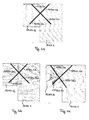
- FIG. 1a-1b is a main / secondary beam connection according to the WO 01/65018 shown, in which two screws 1020.1, 1020.2 come to lie in two mutually parallel planes.
- FIG. 1a shows a section through a plane in which one of the two connecting screws 1020.1, 1020.2 comes to rest. The plane of the other screw is parallel to it. This is from the 3-dimensional view in FIG. 1b seen.
- the wooden beams are labeled 1010.1 and 1010.2.
- the first screw 1020.1 comes to lie in a first plane 1021.1, which is substantially perpendicular to the surface 1023 of the wooden beam 1010.2.
- the second screw 1020.2 comes to rest in a second level 1021.2.
- the level 1021.2 is also perpendicular to the surface 1023 of the wooden beam 1010.2. How out FIG. 1b shows the levels 1021.1, 1021.2, in which the screws come to rest substantially parallel to each other, ie the levels 1021.1, 1021.2 and thus lying in the planes screws 1020.1, 1020.2 do not penetrate.
- the wooden beams 1010.1, 1010.2 to be connected abut each other at right angles.
- the two sections 1020.1.a, 1020.1.b and 1020.2.a and 1020.2.b are the same length. With the same kind of wood optimally large loads are thereby transferred.
- the effects of small inaccuracies are clearly evident in the Fig. 1c to 1e ,
- the threaded sections 1020.1.a, 1020.1.b, 1020.2.a, 1020.2.b are no longer the same length in the two wooden parts to be joined.
- the transferable load decreases by 20% or more compared to the connection in Fig. 1a-b if there are the same types of wood.
- different lengths of the threaded sections may be desired, since the difference in the wood is compensated in relation to the same loads to be removed.
- Fig. 2 the connection of non-perpendicular abutting wooden components is shown.
- the non-rectangular wooden beams to be connected are denoted by the reference numerals 1110.1, 1110.2, the screws with the reference numerals 1120.1, 1120.2.
- Gerbera can be used with a screw, for example, in roof structures. If such carriers used in roof structures, so there is the problem that the dead load of the roof and the snow load not stand perpendicular to the roof pitch. To the wind load perpendicular to the surface of the purlin comes to a parallel load, the suction (snow shovel).
- the loads 1015, 1017 of the connection of the wooden parts 1210.1, 1210.2 are in Fig. 3a located. From the loads 1015 and 1017 in Fig. 3a then the position of the screws, ie, their screwing direction can be determined.
- the position of the screws 1220.1, 1220.2, 1220.3, 1220.4 in a plan view of the carrier consisting of the two wooden beams 1210.1, 1210.2 shows Fig. 3b , How out Fig. 3b
- the planes 1024.1, 1024.2, 1024.3, 1024.4 in which the screws come to rest are not parallel to one another, like the planes 1021.1, 1021.2 according to FIG Fig.
- Layers 1024.1, 1024.2, 1024.3, 1024.4 intersect.
- the in-plane screws do not penetrate because the screws have an inclination angle, not shown, in the plane 1024.1, 1024.2, 1024.3, 1024.4.
- Fig. 4 a section of a wooden structure 3000 is shown.
- the beams of the wooden construction are designated 3010.1, 3010.2, 3010.3, 3010.4.
- the local coordinates are designated 3016.1, 3016.2, 3016.3.
- the coordinate systems 3016.1, 3016.2, 3016.3 are shifted to the general coordinate system 3021 and rotated.
- Fig. 5a-5b is the location of the screws for a complex wooden construction, here a roof construction in a 3-dimensionallane view ( Fig. 5a ) and in a plan view ( Fig. 5b ).
- a total of five bars 4010.1, 4010.2, 4010.3, 4010.4, 4010.5 are interconnected.
- the ridge is labeled 4010.1, the ridge rafters 4010.2, 4010.3 and the rafters 4010.4, and 4010.5.
- the connecting bolts whose position results from the calculation of the loads are designated 4020.1, 4020.2, 4020.3, 4020.4, 4020.5, 4020.6, 4020.7, 4020.8.
- this can be achieved by setting guide bores into which self-tapping connectors, such as full-thread screws, can then be screwed.
- the guide holes are already in the production of wooden beams z. B. introduced on joinery machines.
- the big advantage of these self-drilling, very fast assembled connectors is an economical wood connection that can transmit the highest loads.
- FIG. 6 is a further inventive compound of two wooden components, here two wooden beams 10.1, 10.2, which are shown only partially shown.
- the restriction to two abutting wooden beams is only illustrative and not restrictive.
- connection of the two wooden beams 10.1, 10.2 is along the surface 12 at which the two wooden beams abut each other, made by four arbitrarily oriented in space screws 20.1, 20.2, 20.3, 20.4.
- an elastic material can be introduced between the abutting surfaces of the two wooden beams.
- This elastic material may for example be a layer in the form of a wood fiber or a mineral fiber board, and plastic plates would be possible.
- the thickness of such a layer may be in the range of 0.1 mm to 10 cm and preferably comprise a soft material, wherein the softness or the elasticity is less than the softness or elasticity of the wooden beams. Due to the elastic intermediate layer in the area the area 12 of the wooden beams to be joined is achieved so that the shrinkage and the swelling of the wood is compensated when connecting two wooden beams and a gap that is formed between the abutting wooden beams, can be closed.
- FIG. 6 how out FIG. 6 As can be seen, the screws 20.1, 20.2, 20.3, 20.4 are screwed into different planes, wherein none of the planes in which the screws 20.1, 20.2, 20.3, 20.4 come to rest are parallel to one another.
- full-thread screws are for example in the DE 10 2006 057 259 A1 or DE 10 2005 039 744 A1 or the DE 10 2004 068 069 A1 described.
- full-thread screws are not very suitable. To anyway To transfer shear loads, they can be divided into tensile and compressive loads.
- guide bores are usually sized in length so that on the one hand the position of the self-tapping screw is determined exactly, on the other hand, a running of the drill does not occur, so that the predetermined positions and solid angles can be met accurately.
- FIG. 6 It can also be seen that, in the case of the illustrated connection, when the screw is projected into a projection plane, for example into the surface defined by the abutting surfaces, there are 12 crossing points in this projection plane.
- connections are also conceivable in which the screws do not intersect in any projection plane. This is particularly the case when connections or wood connections are in an inclined plane, z. B. on a roof.
- the wind loads are perpendicular to the roof level, but the intrinsic and snow loads are vertical. Wind bandages can also load the timber joints in the roof parallel to the roof level. Thus loads occur in all three dimensions.
- the screw-in point and the solid angle of the screws 20.1, 20.2, 20.3, 20.4 are just chosen so that exactly one half of the thread 30.1.1 each screw, for example, the screw 20.1 in the one wood component 10.1 and the other half 30.1. 2 of the thread in the other timber component 10.2 comes to rest.
- the transferable loads which are always determined by the shorter threaded part, at the same species of wood to be joined wood components 10.1, 10.2 maximum.
- the length of the guide bores is usually measured according to the core diameter of the full-thread screws 20.1, 20.2, 20.3, 20.4. In the present case, the engagement length has been designated by the reference symbol L for the full-threaded screw 20.2.
- the guide bore length is between 5 times to 30 times the core diameter of the thread. It is particularly preferred if the guide bore length is in the range of 10 times to 15 times the core diameter of the screw to be screwed.
- the guide holes are, for example, at core diameters of 10 mm at 600 mm screw length and 8 mm at 400 mm screw length in the range of 40 mm to 300 mm, preferably in the range of 80mm to 150mm .
- the guide holes have a diameter which is substantially the Core diameter of the screw corresponds, with a few tenths of a millimeter deviations are possible.
- the guide bores are not introduced on the construction site, but already in the production of wood parts, for example on the joinery.
- the By means of data files from the CAD certain screw-in points and solid angles are transferred via CAM to the joinery machine and drilled there.
- stencils that are used, for example, on the construction site for introducing the guide bore become superfluous.
- the connecting bolts have an average diameter in straight millimeters, for example 4, 5, 6 and 8 mm in an automated pre-drilling with the aid of drills on joinery machines, instead of the usual outside diameters of even millimeters, which is used in current screws.
- FIG. 7 is a possible way of using connected by means of the invention wooden beams outside the support, shown more precisely outside the moment zero point of the wearer.
- the in FIG. 7 shown Gerberlie may have a plurality of joints, one of which is shown at the point 110, which consists of two pairs of screws 100.1 and 100.2, which connect the two wooden beams according to the invention. If no automated transmission of the guide holes in the production on joinery, so this could also be using template according to the predetermined positions and solid angles from the calculations on the site in the respective Gerbergelenke 100.1, 100.2 are introduced This is not preferred because of every single geometry would have to be made its own template.
- the gerber joints 100.1, 100.2 are connected with screws 120.1, 120.2, 120.3, 120.4.
- the screw-in point and the solid angles are preferably determined with the aid of a separate, external program from which the data is then transferred to a CAD program.
- the CAD program can then pass the data for the holes to be pre-drilled to the joinery machine together with the other cut data.
- the external program which determines the data of the position of a screw, can also be attached directly to the file for the cutting data of the CAD program for the joinery machine.
- a gerber joint are in turn the screws in different planes, which need not be parallel to each other, screwed. In this way, it is possible to derive snow loads and the dead load of the structure parallel to the roof level.
- Such parallel to the roof plane resulting loads can be taken with conventional joints of gerber joints with full-thread screws, in which the full-thread screws lie with parallel planes to the longitudinal axis of the wooden beam, in only a very limited extent.
- Fig. 8a shown a derivative of shear forces perpendicular to the screw axis of a full-threaded screw, as in Fig. 8a shown, barely possible.
- the screws are in Fig. 8a represented by the reference numerals 400.1, 400.2, the thrust forces occurring perpendicular to the full-thread screws with reference numerals 410.1, 410.2, 410.3.
- the invention thus makes it possible for the first time to specify a connection, in particular, between wooden supports to be joined, with which loads can be removed in different directions. Furthermore, a method is specified, with which the connecting elements, in particular connecting screws can be securely screwed into the predetermined positions.
Landscapes
- Engineering & Computer Science (AREA)
- Architecture (AREA)
- Physics & Mathematics (AREA)
- Electromagnetism (AREA)
- Civil Engineering (AREA)
- Structural Engineering (AREA)
- Joining Of Building Structures In Genera (AREA)
- Connection Of Plates (AREA)
- Rod-Shaped Construction Members (AREA)
Priority Applications (2)
| Application Number | Priority Date | Filing Date | Title |
|---|---|---|---|
| EP09007657A EP2133482A3 (fr) | 2008-06-11 | 2009-06-10 | Procédé destiné à la liaison de deux composants en bois |
| EP12003635A EP2500477A1 (fr) | 2008-06-11 | 2009-06-10 | Procédé destiné à la liaison de deux composants en bois |
Applications Claiming Priority (3)
| Application Number | Priority Date | Filing Date | Title |
|---|---|---|---|
| DE200810027873 DE102008027873B4 (de) | 2008-06-11 | 2008-06-11 | Verbindung von zwei Holzbalken |
| EP20080022085 EP2133480B1 (fr) | 2008-06-11 | 2008-12-19 | Procédé destiné à la liaison de deux composants en bois |
| EP09007657A EP2133482A3 (fr) | 2008-06-11 | 2009-06-10 | Procédé destiné à la liaison de deux composants en bois |
Related Child Applications (1)
| Application Number | Title | Priority Date | Filing Date |
|---|---|---|---|
| EP12003635A Division EP2500477A1 (fr) | 2008-06-11 | 2009-06-10 | Procédé destiné à la liaison de deux composants en bois |
Publications (2)
| Publication Number | Publication Date |
|---|---|
| EP2133482A2 true EP2133482A2 (fr) | 2009-12-16 |
| EP2133482A3 EP2133482A3 (fr) | 2011-08-17 |
Family
ID=40373503
Family Applications (4)
| Application Number | Title | Priority Date | Filing Date |
|---|---|---|---|
| EP20080022085 Not-in-force EP2133480B1 (fr) | 2008-06-11 | 2008-12-19 | Procédé destiné à la liaison de deux composants en bois |
| EP09007281A Withdrawn EP2133481A3 (fr) | 2008-06-11 | 2009-06-02 | Liaison de deux poutres en bois |
| EP12003635A Withdrawn EP2500477A1 (fr) | 2008-06-11 | 2009-06-10 | Procédé destiné à la liaison de deux composants en bois |
| EP09007657A Withdrawn EP2133482A3 (fr) | 2008-06-11 | 2009-06-10 | Procédé destiné à la liaison de deux composants en bois |
Family Applications Before (3)
| Application Number | Title | Priority Date | Filing Date |
|---|---|---|---|
| EP20080022085 Not-in-force EP2133480B1 (fr) | 2008-06-11 | 2008-12-19 | Procédé destiné à la liaison de deux composants en bois |
| EP09007281A Withdrawn EP2133481A3 (fr) | 2008-06-11 | 2009-06-02 | Liaison de deux poutres en bois |
| EP12003635A Withdrawn EP2500477A1 (fr) | 2008-06-11 | 2009-06-10 | Procédé destiné à la liaison de deux composants en bois |
Country Status (2)
| Country | Link |
|---|---|
| EP (4) | EP2133480B1 (fr) |
| DE (1) | DE102008027873B4 (fr) |
Families Citing this family (3)
| Publication number | Priority date | Publication date | Assignee | Title |
|---|---|---|---|---|
| SE537689C2 (sv) * | 2013-12-12 | 2015-09-29 | Martinson Group Ab | Knutpunkt mellan konstruktionselement av trä samt fackverk |
| CN108517972B (zh) * | 2018-04-20 | 2019-09-20 | 广东大喜装饰设计工程有限公司 | 仿木建筑及其钢木连接结构 |
| DE102020114613A1 (de) * | 2020-06-02 | 2021-12-02 | Fischerwerke Gmbh & Co. Kg | Verfahren zu einer Prüfung einer Berührung zweier in Holz geschraubter, elektrisch leitender Schrauben und Handschraubmaschine zur Durchführung des Verfahrens |
Citations (10)
| Publication number | Priority date | Publication date | Assignee | Title |
|---|---|---|---|---|
| FR865513A (fr) | 1940-05-09 | 1941-05-26 | Assemblage de bois | |
| DE706759C (de) | 1937-06-16 | 1941-06-05 | Samuel Voss | Holzverbindung durch metallene Schrauben |
| DE19712175A1 (de) | 1997-03-22 | 1997-10-16 | Beez Fredi Dipl Masch Ing | Gewindebuchsen zum Verbinden von Holz-Treppenteilen |
| DE19724284A1 (de) | 1997-06-09 | 1998-12-17 | Sfs Ind Holding Ag | Koppelpfette aus wenigstens zwei aneinander anschließenden Holzbalken sowie Befestigungselement zum Einsatz bei dieser Koppelpfette |
| DE29920853U1 (de) | 1999-11-30 | 2000-03-02 | Kob, Sabine, 95448 Bayreuth | Wetterfester Wandaufbau in der Blockbauweise |
| WO2001065018A1 (fr) | 2000-02-29 | 2001-09-07 | Sfs Intec Holding Ag | Assemblage de deux poutres en bois se raccordant mutuellement au moins approximativement a angle droit |
| DE102004018069A1 (de) | 2004-04-08 | 2004-08-26 | Rensburg, Markus, Dipl.-Wirtsch.-Ing. | Schraube insbesonder Holzsenkschraube und Verfahren zu deren Herstellung |
| DE102005039744A1 (de) | 2005-08-23 | 2007-03-01 | Rensburg, Markus, Dipl.-Wirtsch.-Ing. | Schraube, insbesondere Holzsenkschraube, Distanzleiste und Verbundsystem |
| DE102006057259A1 (de) | 2006-11-22 | 2008-05-29 | Swg Schraubenwerk Gaisbach Gmbh | Schraube |
| EP2003348A2 (fr) | 2007-06-15 | 2008-12-17 | Adolf Würth GmbH & Co. KG | Vis et son utilisation |
Family Cites Families (9)
| Publication number | Priority date | Publication date | Assignee | Title |
|---|---|---|---|---|
| CH478997A (de) * | 1968-05-30 | 1969-09-30 | Henke Jakob Ing Dr | Abbindevorrichtung für die Enden von Eisenbahn-Holzschwellen, Holzmasten, Balken und Edelholzstämmen |
| GB8332533D0 (en) * | 1983-12-06 | 1984-01-11 | Dinardo & Partners | Restoration and strengthening of timber components |
| FR2617081B1 (fr) * | 1987-06-29 | 1992-04-24 | Guy Perron | Assemblage de pieces de bois et son procede de realisation |
| ATE141986T1 (de) * | 1989-11-16 | 1996-09-15 | Sfs Handels Holding Ag | Verbundkonstruktion aus einem holzbalken bzw. - träger aufweisenden tragwerk und einer ortbetonplatte |
| FI98280C (fi) * | 1994-08-02 | 1997-05-26 | Finnforest Oy | Esivalmistettu liitosrakenne |
| CA2207234A1 (fr) | 1996-06-10 | 1997-12-10 | Ats Automation Tooling Systems Inc. | Arbre excentrique compose de plusieurs pieces et methode de fabrication |
| DE20120208U1 (de) * | 2001-12-13 | 2003-04-24 | Guttendörfer, Dieter, 91522 Ansbach | Verbindung von aus Holzbalken oder -Latten bestehenden Pfosten und Riegeln zur Bildung von Wandelementen |
| US6922951B1 (en) * | 2003-01-16 | 2005-08-02 | Metal-Era, Inc. | Lighted roof edge assembly |
| EP1690990A2 (fr) * | 2005-02-09 | 2006-08-16 | SFS intec Holding AG | Assemblage de montants et de traverses formés de poutres ou de lattes en bois pour la construction d'éléments de murs |
-
2008
- 2008-06-11 DE DE200810027873 patent/DE102008027873B4/de not_active Expired - Fee Related
- 2008-12-19 EP EP20080022085 patent/EP2133480B1/fr not_active Not-in-force
-
2009
- 2009-06-02 EP EP09007281A patent/EP2133481A3/fr not_active Withdrawn
- 2009-06-10 EP EP12003635A patent/EP2500477A1/fr not_active Withdrawn
- 2009-06-10 EP EP09007657A patent/EP2133482A3/fr not_active Withdrawn
Patent Citations (10)
| Publication number | Priority date | Publication date | Assignee | Title |
|---|---|---|---|---|
| DE706759C (de) | 1937-06-16 | 1941-06-05 | Samuel Voss | Holzverbindung durch metallene Schrauben |
| FR865513A (fr) | 1940-05-09 | 1941-05-26 | Assemblage de bois | |
| DE19712175A1 (de) | 1997-03-22 | 1997-10-16 | Beez Fredi Dipl Masch Ing | Gewindebuchsen zum Verbinden von Holz-Treppenteilen |
| DE19724284A1 (de) | 1997-06-09 | 1998-12-17 | Sfs Ind Holding Ag | Koppelpfette aus wenigstens zwei aneinander anschließenden Holzbalken sowie Befestigungselement zum Einsatz bei dieser Koppelpfette |
| DE29920853U1 (de) | 1999-11-30 | 2000-03-02 | Kob, Sabine, 95448 Bayreuth | Wetterfester Wandaufbau in der Blockbauweise |
| WO2001065018A1 (fr) | 2000-02-29 | 2001-09-07 | Sfs Intec Holding Ag | Assemblage de deux poutres en bois se raccordant mutuellement au moins approximativement a angle droit |
| DE102004018069A1 (de) | 2004-04-08 | 2004-08-26 | Rensburg, Markus, Dipl.-Wirtsch.-Ing. | Schraube insbesonder Holzsenkschraube und Verfahren zu deren Herstellung |
| DE102005039744A1 (de) | 2005-08-23 | 2007-03-01 | Rensburg, Markus, Dipl.-Wirtsch.-Ing. | Schraube, insbesondere Holzsenkschraube, Distanzleiste und Verbundsystem |
| DE102006057259A1 (de) | 2006-11-22 | 2008-05-29 | Swg Schraubenwerk Gaisbach Gmbh | Schraube |
| EP2003348A2 (fr) | 2007-06-15 | 2008-12-17 | Adolf Würth GmbH & Co. KG | Vis et son utilisation |
Also Published As
| Publication number | Publication date |
|---|---|
| EP2133480B1 (fr) | 2012-12-19 |
| EP2133482A3 (fr) | 2011-08-17 |
| DE102008027873A1 (de) | 2009-12-24 |
| EP2133481A3 (fr) | 2011-11-09 |
| EP2133480A1 (fr) | 2009-12-16 |
| EP2500477A1 (fr) | 2012-09-19 |
| EP2133481A2 (fr) | 2009-12-16 |
| DE102008027873B4 (de) | 2010-05-12 |
Similar Documents
| Publication | Publication Date | Title |
|---|---|---|
| EP3559484B1 (fr) | Système d'assemblage ou de blindage de composants | |
| EP3433440B1 (fr) | Procédé d'assemblage de poutres en bois | |
| EP2227605A2 (fr) | Procédé de production d'un assemblage longitudinal pour composants en bois, et composant en bois correspondant | |
| EP1015774B1 (fr) | Fixation des lattes de bois sur le platelage d'un toit ou la fondation d'un mur composé entre autres de bois | |
| WO2018166773A1 (fr) | Élément de raccordement pour le vissage en biais de deux pièces | |
| EP2821562A2 (fr) | Structure composite en bois/béton | |
| DE102011102825B4 (de) | Verbindungsanordnung und Verfahren zur Herstellung einer Durchstanzsicherung | |
| EP2133482A2 (fr) | Procédé destiné à la liaison de deux composants en bois | |
| EP2977528B1 (fr) | Système de renfort d'un ouvrage et procédé destiné à renforcer un ouvrage doté d'un tel système de renfort | |
| EP0988430B1 (fr) | Panne de couplage constituee de deux ou plusieurs poutres en bois jointes l'une a l'autre par chevauchement longitudinal, ainsi qu'element de fixation pour relier deux zones d'extremite se chevauchant de poutres en bois a utiliser pour une panne de couplage | |
| WO2014067924A1 (fr) | Procédé d'assemblage d'éléments préfabriqués en béton | |
| DE102007057291A1 (de) | Verfahren zur Herstellung einer Eckverbindung für Beton-Fertigteile | |
| EP2096217B1 (fr) | Liaison pour structures de poutres en bois | |
| EP1699986B1 (fr) | Construction de parois en bois, du type a madriers en blocs | |
| DE3318751A1 (de) | Kraftuebertragende holzverbindung | |
| EP2954125B1 (fr) | Construction porteuse en bois comportant un élément porteur en forme de barre ou plat et au moins un deuxième élément porteur en forme de barre ou plat | |
| EP4459073A1 (fr) | Renforcement pour un support de béton poreux, support de béton poreux, utilisation d'un support de béton poreux, procédé de renforcement d'un support de béton poreux et utilisation d'un renforcement | |
| EP2126241A1 (fr) | Poutre en bois | |
| EP3807523B1 (fr) | Dispositif pour l'introduction de force longitudinale ou de traction ainsi que procédé pour la fabrication d'un tel dispositif | |
| EP2409821A1 (fr) | Procédé de fabrication d'éléments de plaque | |
| AT506192B1 (de) | Verbindungselement | |
| EP4221936A1 (fr) | Plaque avec au moins une fente dans sa surface, procédé de fabrication d'une fente dans la surface d'une plaque, et écrou à fente | |
| AT528128B1 (de) | Modulbauhausabschnitt mit einem Schienensystem | |
| EP4717934A1 (fr) | Tôle à structures estampées pour relier deux éléments en bois, assemblage de deux éléments en bois avec la tôle et procédé de fabrication de la tôle | |
| EP4678838A1 (fr) | Liaison d'élément de paroi, de plafond, de façade ou de toit |
Legal Events
| Date | Code | Title | Description |
|---|---|---|---|
| PUAI | Public reference made under article 153(3) epc to a published international application that has entered the european phase |
Free format text: ORIGINAL CODE: 0009012 |
|
| AK | Designated contracting states |
Kind code of ref document: A2 Designated state(s): AT BE BG CH CY CZ DE DK EE ES FI FR GB GR HR HU IE IS IT LI LT LU LV MC MK MT NL NO PL PT RO SE SI SK TR |
|
| 17P | Request for examination filed |
Effective date: 20091222 |
|
| PUAL | Search report despatched |
Free format text: ORIGINAL CODE: 0009013 |
|
| AK | Designated contracting states |
Kind code of ref document: A3 Designated state(s): AT BE BG CH CY CZ DE DK EE ES FI FR GB GR HR HU IE IS IT LI LT LU LV MC MK MT NL NO PL PT RO SE SI SK TR |
|
| AX | Request for extension of the european patent |
Extension state: AL BA RS |
|
| RIC1 | Information provided on ipc code assigned before grant |
Ipc: F16B 25/00 20060101ALI20110714BHEP Ipc: E04B 1/26 20060101AFI20110714BHEP |
|
| 17Q | First examination report despatched |
Effective date: 20120417 |
|
| STAA | Information on the status of an ep patent application or granted ep patent |
Free format text: STATUS: THE APPLICATION IS DEEMED TO BE WITHDRAWN |
|
| 18D | Application deemed to be withdrawn |
Effective date: 20140918 |