EP2135333B1 - Verlängerungskabel für elektrische rohrbearbeitungsvorrichtungen - Google Patents
Verlängerungskabel für elektrische rohrbearbeitungsvorrichtungen Download PDFInfo
- Publication number
- EP2135333B1 EP2135333B1 EP08708374.7A EP08708374A EP2135333B1 EP 2135333 B1 EP2135333 B1 EP 2135333B1 EP 08708374 A EP08708374 A EP 08708374A EP 2135333 B1 EP2135333 B1 EP 2135333B1
- Authority
- EP
- European Patent Office
- Prior art keywords
- cable
- plug
- coupling
- pipe
- electrical
- Prior art date
- Legal status (The legal status is an assumption and is not a legal conclusion. Google has not performed a legal analysis and makes no representation as to the accuracy of the status listed.)
- Active
Links
Images


Classifications
-
- H—ELECTRICITY
- H01—ELECTRIC ELEMENTS
- H01R—ELECTRICALLY-CONDUCTIVE CONNECTIONS; STRUCTURAL ASSOCIATIONS OF A PLURALITY OF MUTUALLY-INSULATED ELECTRICAL CONNECTING ELEMENTS; COUPLING DEVICES; CURRENT COLLECTORS
- H01R27/00—Coupling parts adapted for co-operation with two or more dissimilar counterparts
-
- H—ELECTRICITY
- H01—ELECTRIC ELEMENTS
- H01R—ELECTRICALLY-CONDUCTIVE CONNECTIONS; STRUCTURAL ASSOCIATIONS OF A PLURALITY OF MUTUALLY-INSULATED ELECTRICAL CONNECTING ELEMENTS; COUPLING DEVICES; CURRENT COLLECTORS
- H01R13/00—Details of coupling devices of the kinds covered by groups H01R12/70 or H01R24/00 - H01R33/00
- H01R13/62—Means for facilitating engagement or disengagement of coupling parts or for holding them in engagement
- H01R13/639—Additional means for holding or locking coupling parts together, after engagement, e.g. separate keylock, retainer strap
- H01R13/6392—Additional means for holding or locking coupling parts together, after engagement, e.g. separate keylock, retainer strap for extension cord
-
- H—ELECTRICITY
- H01—ELECTRIC ELEMENTS
- H01R—ELECTRICALLY-CONDUCTIVE CONNECTIONS; STRUCTURAL ASSOCIATIONS OF A PLURALITY OF MUTUALLY-INSULATED ELECTRICAL CONNECTING ELEMENTS; COUPLING DEVICES; CURRENT COLLECTORS
- H01R35/00—Flexible or turnable line connectors, i.e. the rotation angle being limited
- H01R35/02—Flexible line connectors without frictional contact members
- H01R35/025—Flexible line connectors without frictional contact members having a flexible conductor wound around a rotation axis
-
- H—ELECTRICITY
- H01—ELECTRIC ELEMENTS
- H01R—ELECTRICALLY-CONDUCTIVE CONNECTIONS; STRUCTURAL ASSOCIATIONS OF A PLURALITY OF MUTUALLY-INSULATED ELECTRICAL CONNECTING ELEMENTS; COUPLING DEVICES; CURRENT COLLECTORS
- H01R35/00—Flexible or turnable line connectors, i.e. the rotation angle being limited
- H01R35/04—Turnable line connectors with limited rotation angle with frictional contact members
-
- H—ELECTRICITY
- H01—ELECTRIC ELEMENTS
- H01R—ELECTRICALLY-CONDUCTIVE CONNECTIONS; STRUCTURAL ASSOCIATIONS OF A PLURALITY OF MUTUALLY-INSULATED ELECTRICAL CONNECTING ELEMENTS; COUPLING DEVICES; CURRENT COLLECTORS
- H01R39/00—Rotary current collectors, distributors or interrupters
- H01R39/64—Devices for uninterrupted current collection
Definitions
- the invention relates to a flexible electrical extension cable
- the separating device is rotatably arranged on the clamping device about a tube longitudinal axis defined by the clamping device.
- the separating device includes a tool holder for holding a cutting tool, such as a circular saw blade, and an electric motor for the rotational drive of the tool holder together with the cutting tool attached to it.
- the separating device has a transverse to the tube longitudinal axis, for example, radially projecting lever-like projection, which is designed as a handle or can be provided with a handle for rotating the separator about the tube longitudinal axis.
- the electric motor may be housed in the lever-like projection.
- a cable is connected to the separator for the electrical power to the electric motor.
- the cable has a cable end electrically connected in the disconnecting device, for example in the lever-like projection.
- a cable connector is connected, which is adapted to the standard sockets of the public power grid and therefore plugged into such sockets for electrical connection between the public grid and the cable.
- the cable contains at least two electrically conductive wires.
- the separating element can be, for example, a circular saw blade or a cut-off wheel.
- the invention is also applicable to pipe cutting devices according to the DE 100 20 393 A1 applicable. Furthermore, it is applicable to pipe end processing equipment, as for example from the DE 197 26 498 A1 , of the DE 100 14 578 A1 and the DE 102 16 787 A1 are known. The invention is also applicable to combined pipe cutting and pipe end processing devices, as for example from the DE 196 03 361 A1 are known. This device is used for separating pipes and for preheating pipe ends, in particular of thin-walled metal pipes.
- the invention is applicable to pipe cutting devices, as for example from the US 4,890,385 and 6,065,212 are known. They contain a motor for driving a rotary body, which is rotatably mounted in a housing and carries the pipe cutting tool. By means of the motor and the separating tool is moved radially to the pipe to be separated.
- the housing and the rotary body have a radial access opening through which the pipe separator is radially attachable to a pipe to be separated.
- the sockets of public power grids are designed differently in many countries.
- the cable connector designed as a plug of the fit Pipe processing devices usually only in the sockets of the public power grid of one country, but not in the sockets of the public power grid of other countries. Therefore, the manufacturers of such pipe processing apparatuses have to manufacture and stock a variety of different pipe processing apparatuses corresponding to the plurality of different power outlets of the various countries, and take into account the socket type of the country concerned in the shipment.
- Pipe processing devices such as pipe cutters and / or pipe end processing devices are exposed to harsh working conditions and environmental conditions. They are used in pipe processing workshops and on building shell buildings. Therefore, the flexible electrical cables of the tube processing devices are very often damaged and they must be replaced.
- the replacement of an electrical cable requires opening the tube processing device and connecting the electrically conductive wires of a new cable within the tube processing device and properly attaching a strain relief device for the cable in the tube processing device.
- the replacement of a cable should, for safety reasons, not be performed by the pipe man skilled in the art who uses the pipe working device, but by a qualified electrician. This means that the pipe processing device must be brought to a power workshop for replacement of a cable and then retrieved.
- the cable of the tube processing apparatuses is damaged not only by being crushed by persons standing on the cable or by metallic objects falling on the cable, but also by the cable being damaged by forces through which the cable is stretched and almost pulled is torn apart by a person walking on the cable or by an object falling on the cable.
- Another source of damage is that the cable is twisted frequently during use and then twisted by a person for the purpose of Entdrillens is not completely back-drilled, but by pulling the cable, the cable is stretched.
- the problem to be solved is to improve the handling of pipe processing devices.
- a tube processing device which has a stationary mounted on her electrical plug or a cable plug, which is adapted to a cable coupling of the extension cable according to the invention.
- flexible electrical extension cable 2 contains at least two electrically conductive wires.
- the extension cable 2 is split into a front cable piece 2-1 and a rear cable piece 2-2.
- the two cable pieces 2-1 and 2-2 are connected to each other by a rotary coupling 4, so that the two cable pieces 2-1 and 2-2 are rotatable relative to each other about their longitudinal axis.
- the cable coupling 8 has a different construction than sockets of public power grids, such that the cable connector 6 does not fit into the cable coupling 8 and thus can not be plugged together so that they are not connectable to each other for establishing an electrical connection.
- the cable coupling 8 can be plugged together only with a cable plug adapted to it or with an electrical plug which is adapted to it and fixedly attached to a pipe-working device in order to form an electrical connection.
- the number of sockets 12, 13, 14 and the number of connector pins 22, 23, 24 is at least two, but may be another number, for. For example, three, five, six or more. The number may be higher than is needed electrically, for example, if connectors and / or couplings with a higher number are cheaper than those with a lower number.
- a cable coupling 20 Connected to the external end of the external cable section 54 projecting out of the housing 52 is a cable coupling 20 which is adapted to the cable coupling 8 of the extension cable 2 so as to be mated therewith to establish an electrical connection.
- the external cable connector may be the one with reference to Fig. 4 be described cable connector 20.
- an electrical connector for example on the housing 52, which is adapted to the cable coupling 8 of the extension cable 2, so as to produce a electrical connection to be plugged together.
- the rotary joint 4 contains, as in Fig. 1 is shown schematically, two relatively rotatable about the cable longitudinal axis coupling parts 4-1 and 4-2.
- the one coupling part 4-1 contains at the rear end of the front cable piece 2-1 with its wires, of which two pieces 62 and 63 are shown, electrically connected contacts 64 and 66, which on contacts 78 and 80 of the other coupling part 4-. 2 slide.
- These further contacts 78 and 80 are connected at the front end of the rear cable piece 2-2 with the electrically conductive wires 82 and 83 (or more) of the rear cable piece 2-2.
- Fig. 5 shows a lever-like extension 90 for a tube processing device 40 of Fig. 1
- the lever-like extension 90 may, for example, contain the electric motor 42 and be provided with one or two handles 91 and / or 92.
- the external cable section 54 with the external plug 20 extends at the external end of the lever through a cable protection sleeve 93 and a housing opening 94 into a housing part 95 of the lever-like extension 90.
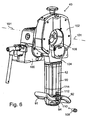
- Fig. 6 shows an example of how the tube processing device 40 can be formed in detail. It contains, for example, a tube clamping device 100, for example in the form of a vice, in which a tube to be machined can be clamped and which defines a tube longitudinal axis 101 of the tube to be machined.
- a rotary body 102 is rotatably mounted about the tube longitudinal axis 101.
- a slider 104 is arranged radially displaceable to the tube longitudinal axis 101.
- the slider 104 carries a rotatably mounted tool holder (not shown) for a pipe-working tool 106, for example a pipe-cutting tool, for example in the form of a circular saw blade or a cut-off wheel.
- a pipe end machining tool could also be provided.
- the lever-like extension 90 extends transversely to the tube longitudinal axis 101, for example radially thereto.
- Fig. 6 14 shows the housing opening 94 for the connection cable 50 of the tube processing device 40.
- an electrical connector 108 could be fixedly mounted on the tube processing device 40, in particular on the extension 90 thereof, which is designed to connect to the sockets of a public power grid is not attachable, but is adapted to the cable coupling 8 of the extension cable 2 so that it can be plugged together with the cable coupling 8 for establishing an electrical connection therebetween.
- the housing opening 94 is not needed in this case.
- the plug 108 may, for. B. at the point where the housing opening 94 was.
- an on and off switch 110 for switching on and off of the electric motor 42 may be provided on the lever-like extension 90.
- a speed controller 112 may be provided for controlling the rotational speed of the electric motor 42.
- the lever-like extension 90 may include electronics 114 which, for example, regardless of the load on the tool 106 holds the set at the speed controller 112 engine speed constant.
- lever-like projection 90 itself may be formed as a handle.
Landscapes
- Electric Cable Installation (AREA)
- Details Of Indoor Wiring (AREA)
- Sawing (AREA)
Description
- Die Erfindung betrifft ein flexibles elektrisches Verlängerungskabel
- Eine Rohrbearbeitungsvorrichtung in Form einer Rohrtrennvorrichtung ist aus der
DE 103 52 890 A1 (=US 2005/0097752 A1 ) bekannt. Ähnliche Rohrtrennvorrichtungen sind auch aus derCH-Patentschrift 372202 DE 101 34 269 B4 bekannt. Sie enthalten eine Einspannvorrichtung zum Einspannen eines abzutrennenden Rohres und eine Trennvorrichtung zum Trennen des eingespannten Rohres. Die Trennvorrichtung ist an der Einspannvorrichtung um eine durch die Einspannvorrichtung definierte Rohrlängsachse drehbar angeordnet. Die Trennvorrichtung enthält einen Werkzeughalter zum Halten eines Trennwerkzeuges, beispielsweise eines Kreissägeblattes, und einen elektrischen Motor für den Rotationsantrieb des Werkzeughalters zusammen mit dem an ihm befestigten Trennwerkzeug. Die Trennvorrichtung hat einen quer zur Rohrlängsachse, beispielsweise radial, wegragenden hebelartigen Vorsprung, welcher als Handgriff ausgebildet ist oder mit einem Handgriff versehen sein kann zum Drehen der Trennvorrichtung um die Rohrlängsachse. Der elektrische Motor kann in dem hebelartigen Vorsprung untergebracht sein. Üblicherweise ist an die Trennvorrichtung ein Kabel angeschlossen für die elektrische Stromzufuhr zum elektrischen Motor. Das Kabel hat ein in der Trennvorrichtung, beispielsweise in dem hebelartigen Vorsprung, elektrisch angeschlossenes Kabelende. An das von der Trennvorrichtung entfernte externe Ende des Kabels ist ein Kabelstecker angeschlossen, welcher an die handelsüblichen Steckdosen des öffentlichen Stromnetzes adaptiert ist und deshalb in solche Steckdosen steckbar ist zur elektrischen Verbindung zwischen dem öffentlichen Stromnetz und dem Kabel. Das Kabel enthält mindestens zwei elektrisch leitende Adern. - Das Trennelement kann beispielsweise ein Kreissägeblatt oder eine Trennschleifscheibe sein.
- Die Erfindung ist auch auf Rohrtrennvorrichtungen gemäß der
DE 100 20 393 A1 anwendbar. Ferner ist sie auf Rohrendenbearbeitungsgeräte anwendbar, wie sie beispielsweise aus derDE 197 26 498 A1 , derDE 100 14 578 A1 und derDE 102 16 787 A1 bekannt sind. Die Erfindung ist auch auf kombinierte Rohrtrenn- und Rohrendenbearbeitungsvorrichtungen anwendbar, wie sie beispielsweise aus derDE 196 03 361 A1 bekannt sind. Diese Vorrichtung dient zum Trennen von Rohren und zum Anphasen von Rohrenden, insbesondere von dünnwandigen Metallrohren. - Ferner ist die Erfindung auf Rohrtrennvorrichtungen anwendbar, wie sie beispielsweise aus den
US 4,890,385 und6,065,212 bekannt sind. Sie enthalten einen Motor zum Antrieb eines Drehkörpers, welcher in einem Gehäuse drehbar gelagert ist und das Rohrtrennwerkzeug trägt. Mittels des Motors wird auch das Trennwerkzeug radial zu dem abzutrennenden Rohr bewegt. Das Gehäuse und der Drehkörper haben eine radiale Zugangsöffnung, durch welche die Rohrtrennvorrichtung radial auf ein zu trennendes Rohr aufsteckbar ist. - Die Steckdosen von öffentlichen Stromnetzen sind in vielen Ländern unterschiedlich ausgebildet. Dadurch passen die als Netzstecker ausgebildeten Kabelstecker der Rohrbearbeitungsvorrichtungen meistens nur in die Steckdosen des öffentlichen Stromnetzes von einem Land, jedoch nicht in die Steckdosen des öffentlichen Stromnetzes von anderen Ländern. Deshalb müssen die Hersteller von solchen Rohrbeärbeitungsvorrichtungen eine der Vielzahl der verschiedenen Steckdosen der verschiedenen Länder entsprechende Vielzahl von unterschiedlichen Rohrbearbeitungsvorrichtungen herstellen und auf Lager halten und bei der Versendung die Steckdosenart des betreffenden Landes berücksichtigen.
- Rohrbearbeitungsvorrichtungen wie Rohrtrennvorrichtungen und/oder Rohrendenbearbeitungsvorrichtungen sind rauen Arbeitsbedingungen und Umweltbedingungen ausgesetzt. Sie werden in Rohrverarbeitungswerkstätten und auf Gebäude-Rohbauten verwendet. Deshalb werden die flexiblen elektrischen Kabel der Rohrbearbeitungsvorrichtungen sehr häufig beschädigt und sie müssen ausgetauscht werden. Der Austausch eines elektrischen Kabels erfordert das Öffnen der Rohrbearbeitungsvorrichtung und das Anschließen der elektrisch leitenden Adern eines neuen Kabels innerhalb der Rohrbearbeitungsvorrichtung und die richtige Anbringung einer Zugentlastungsvorrichtung für das Kabel in der Rohrbearbeitungsvorrichtung. Der Austausch eines Kabels sollte aus Sicherheitsgründen nicht von dem Rohrbearbeitungsfachmann durchgeführt werden, welcher die Rohrbearbeitungsvorrichtung benutzt, sondern von einem qualifizierten Elektriker. Dies bedeutet, dass die Rohrbearbeitungsvorrichtung zum Austausch eines Kabels in eine Elektrowerkstatt gebracht und danach wieder geholt werden muss.
- Das Kabel der Rohrbearbeitungsvorrichtungen wird nicht nur dadurch beschädigt, dass es gequetscht wird durch Personen, die auf das Kabel stehen, oder durch Metallgegenstände, die auf das Kabel fallen, sondern das Kabel wird auch beschädigt durch Kräfte, durch welche das Kabel gestreckt und dabei nahezu auseinander gerissen wird durch eine auf das Kabel tretende Person oder durch einen auf das Kabel fallenden Gegenstand.
- Eine weitere Beschädigungsquelle besteht darin, dass das Kabel während der Benutzung häufig verdrillt wird und danach von einer Person im Zwecke des Entdrillens nicht vollständig zurück-gedrillt wird, sondern durch Ziehen des Kabels das Kabel gestreckt wird.
- Durch die Erfindung soll die Aufgabe gelöst werden, die Handhabung von Rohrbearbeitungsvorrichtungen zu verbessern.
- Diese Aufgabe wird gemäß der Erfindung durch ein flexibles elektrisches Verlängerungskabel mit den Merkmalen des Anspruchs 1 gelöst.
- Ferner wird die Erfindung durch eine Rohrbearbeitungsvorrichtung gemäß den Patentansprüchen gelöst, welche einen ortsfest an ihr montierten elektrischen Stecker oder einen Kabelstecker aufweist, welcher an eine Kabelkupplung des erfindungsgemäßen Verlängerungskabels adaptiert ist.
- Weitere Merkmale der Erfindung sind in den Unteransprüchen enthalten.
- Vorteile der Erfindung: Eine einzige Ausführungsform der Rohrbearbeitungsvorrichtung ist für alle Länder verwendbar. Es werden nur noch verschiedene Verlängerungskabel benötigt. Bei einem Defekt des Verlängerungskabels bleibt die Rohrbearbeitungsvorrichtung betriebsbereit. Sie braucht nicht geöffnet zu werden. Es wird eine höhere Betriebssicherheit erreicht.
- Die Erfindung wird im Folgenden mit Bezug auf die beiliegenden Zeichnungen anhand von bevorzugten Ausführungsformen als Beispiele beschrieben. In den Zeichnungen zeigen
- Fig. 1
- schematisch ein flexibles elektrisches Verlängerungskabel gemäß der Erfindung in Kombination mit einer daran adaptierten Rohrbearbeitungsvorrichtung gemäß der Erfindung,
- Fig. 2
- eine perspektivische Darstellung des Verlängerungskabels von
Fig. 1 , - Fig. 3
- perspektivisch eine Kabelkupplung am hinteren Ende des Verlängerungskabels,
- Fig. 4
- perspektivisch einen Kabelstecker, welcher mit der Kabelkupplung von
Fig. 3 zusammenpasst und zur Bildung einer elektrischen Verbindung dazwischen, - Fig. 5
- der Kabelstecker von
Fig. 4 am externen Ende eines flexiblen elektrischen Kabels, welches sich in das Gehäuse eines hebelartigen Vorsprunges einer Rohrtrennvorrichtung vonFig. 6 erstreckt, - Fig. 6
- eine perspektivische Darstellung einer Rohrtrennvorrichtung, von welcher ein Teil in
Fig. 5 dargestellt ist. - Das in den
Figuren 1 ,2 und3 dargestellte flexible elektrische Verlängerungskabel 2 enthält mindestens zwei elektrisch leitende Adern. Das Verlängerungskabel 2 ist auf ein vorderes Kabelstück 2-1 und ein hinteres Kabelstück 2-2 aufgeteilt. Die beiden Kabelstücke 2-1 und 2-2 sind durch eine Drehkupplung 4 miteinander verbunden, sodass die beiden Kabelstücke 2-1 und 2-2 relativ zueinander um ihre Längsachse verdrehbar sind. - An das vordere Ende des vorderen Kabelstückes 2-1 ist ein mindestens zweiadriger Kabelstecker 6 angeschlossen. An das hintere Ende des hinteren Kabelstückes 2-2 ist eine Kabelkupplung 8 angeschlossen.
- Der Kabelstecker 6 ist ein Netzstecker, welcher derart ausgebildet ist, dass er zur Herstellung einer elektrischen Verbindung in eine Steckdose eines öffentlichen Stromnetzes steckbar ist.
- Die Kabelkupplung 8 hat eine andere Konstruktion als Steckdosen von öffentlichen Stromnetzen, derart, dass der Kabelstecker 6 nicht in die Kabelkupplung 8 passt und damit nicht zusammensteckbar ist, sodass sie nicht zur Herstellung einer elektrischen Verbindung miteinander verbindbar sind. Die Kabelkupplung 8 ist nur mit einem an sie adaptierten Kabelstecker oder mit einem an sie adaptierten, ortsfest an einer Rohrbearbeitungsvorrichtung befestigten elektrischen Stecker zusammensteckbar zur Bildung einer elektrischen Verbindung.
-
Fig. 3 zeigt eine von vielen Möglichkeiten einer solchen Kabelkupplung 8. Sie kann einen zentralen Kupplungszapfen 10 aus elektrisch isolierendem Material aufweisen, in welchem sich entsprechend der Anzahl der Adern des Verlängerungskabels 2 mindestens zwei Steckbuchsen 12, 13 und/oder 14 befinden, deren nach hinten zeigende Enden im Kupplungszapfen vertieft angeordnet sind, sodass sie aus dem Kupplungszapfen 10 nicht herausragen. Zwischen dem Außenumfang des Kupplungszapfens 10 und einem ihn mit radialem Abstand umgebenden Gehäusering 16 ist eine zur hinteren Stirnseite offene Ringnut 18 gebildet. - Mit der Kabelkupplung 8 von
Fig. 3 ist ein ortsfest an einer Rohrbearbeitungsvorrichtung angeordneter elektrischer Stecker oder ein zweiter Kabelstecker 20 vonFig. 4 zur Bildung einer elektrischen Verbindung zusammensteckbar, welcher mit den Steckbuchsen 12, 13, und 14 fluchtend angeordnete Steckerstifte 22, 23 und/oder 24 enthält und mit einer Kupplungsbuchse 26 aus elektrisch isolierendem Material versehen ist, welche alle Steckerstifte 22, 23 und 24 umgibt und in die Ringnut 18 der Kabelkupplung 8 vonFig. 3 passt. Dadurch ist die Kabelkupplung 8 mit dem Kabelstecker 20 vonFig. 3 oder mit einem entsprechend dem Kabelstecker 20 ausgebildeten ortsfesten Stecker zusammensteckbar zur Bildung einer elektrischen Verbindung dazwischen. - Die Anzahl der Steckbuchsen 12, 13, 14 und die Anzahl der Steckerstifte 22, 23, 24 beträgt mindestens zwei, kann jedoch auch eine andere Zahl sein, z. B. drei, fünf, sechs oder mehr. Die Anzahl kann höher sein als elektrisch benötigt wird, beispielsweise wenn Stecker und/oder Kupplungen mit einer höheren Anzahl preiswerter sind als solche mit einer niedrigeren Anzahl.
- Das hintere Kabelstück 2-2 ist mindestens auf einem Teil seiner Länge als eine mehrfache Wendel 30 geformt, sodass dieser Teil wie eine Schraubenfeder ausgebildet ist und in Kabellängsrichtung des hinteren Kabelstückes 2-2 federelastisch expandierbar ist.
-
Fig. 1 zeigt schematische eine Rohrbearbeitungsvorrichtung 40. Sie kann eine Rohrtrennvorrichtung oder eine Rohrendenbearbeitungsvorrichtung oder eine kombinierte Rohrtrenn- und Rohrendenbeärbeitungsvorrichtung sein. Sie enthält einen elektrischen Motor 42, welcher direkt oder über ein Getriebe 44 einen Werkzeugträger 46 mit einem daran befestigten Werkzeug 48 zur Rohrbearbeitung rotatorisch antreibt. Die Rohrbearbeitungsvorrichtung 40 kann zur Stromversorgung des elektrischen Motors 42 ein flexibles elektrisches Kabel 50 aufweisen, welches innerhalb eines Gehäuses 52 der Rohrbearbeitungsvorrichtung 40 mit dem elektrischem Motor 42 über einen (nicht gezeigten) Schalter verbindbar ist. Diese Verbindung kann entweder direkt oder über einen Akkumulator erfolgen. An das externe Ende des aus dem Gehäuse 52 herausragenden externen Kabelabschnittes 54 ist eine Kabelkupplung 20 angeschlossen, welche an die Kabelkupplung 8 des Verlängerungskabels 2 adaptiert ist, um damit zur Herstellung einer elektrischen Verbindung zusammengesteckt zu werden. Der externe Kabelstecker kann der mit Bezug aufFig. 4 beschriebene Kabelstecker 20 sein. - Anstelle eines externen Kabelsteckers 20, welcher an die Kabelkupplung 8 des Verlängerungskabels 2 adaptiert ist, könnte an der Rohrbefestigungsvorrichtung ein elektrischer Stecker ortsfest befestigt sein, beispielsweise an dem Gehäuse 52, welcher an die Kabelkupplung 8 des Verlängerungskabels 2 adaptiert ist, um damit zur Herstellung einer elektrischen Verbindung zusammengesteckt zu werden.
- Damit der externe Kabelstecker 20 der
Figuren 1 und 4 bei der Benutzung der Rohrbearbeitungsvorrichtung nicht am Boden liegt und dort beschädigt werden kann, beträgt die Länge des externen Kabelabschnittes 54 von dem Gehäuse 52 bis zu dem externen Kabelstecker 20 vorzugsweise zwischen 5 cm und maximal 60 cm, wobei die Mindestlänge vorzugsweise mindestens 10 cm beträgt und die maximale Länge vorzugsweise maximal 40 cm oder 30 cm. - Damit die Kabelkupplung 8 und der externe Kabelstecker 20 oder ein anstatt dem externen Kabelstecker 20 vorgesehener ortsfester Stecker der Rohrbearbeitungsvorrichtung 40 nicht versehentlich voneinander trennbar sind, sind sie vorzugsweise jeweils mit einem Verriegelungselement 8-1 bzw. 20-1 versehen, beispielsweise miteinander verschraubbare Gewindeelemente, wie dies in
Fig. 1 schematisch dargestellt ist, oder ein Verriegelungshebel und ein Verriegelungsvorsprung, die mechanisch miteinander verbindbar sind und jeweils erst voneinander getrennt werden müssen, bevor die Kabelkupplung 8 von dem externen Kabelstecker 20 oder einem an die Kabelkupplung 8 adaptierten ortsfesten Stecker der Rohrbearbeitungsvorrichtung 40 getrennt werden kann. Gemäß einer anderen bevorzugten Ausführungsform der Erfindung sind die Verriegelungselemente 8-1 und 20-1 derart ausgebildet, dass sie einen Bajonettverschluss bilden. - Die Drehkupplung 4 enthält, wie dies in
Fig. 1 schematisch dargestellt ist, zwei relativ zueinander um die Kabellängsachse verdrehbare Kupplungsteile 4-1 und 4-2. Der eine Kupplungsteil 4-1 enthält am hinteren Ende des vorderen Kabelstückes 2-1 mit dessen Adern, von welchen zwei Stück 62 und 63 dargestellt sind, elektrisch verbundene Kontakte 64 bzw. 66, welche auf Kontakten 78 bzw. 80 des anderen Kupplungsteiles 4-2 gleiten. Diese weiteren Kontakte 78 und 80 sind am vorderen Ende des hinteren Kabelstücks 2-2 mit den elektrisch leitenden Adern 82 bzw. 83 (oder mehr) des hinteren Kabelstückes 2-2 verbunden. -
Fig. 5 zeigt eine hebelartige Verlängerung 90 für eine Rohrbearbeitungsvorrichtung 40 vonFig. 1 . Die hebelartige Verlängerung 90 kann beispielsweise den elektrischen Motor 42 enthalten und mit einem oder zwei Handgriffen 91 und/oder 92 versehen sein. Der externe Kabelabschnitt 54 mit dem externen Stecker 20 erstreckt sich am externen Hebelende durch eine Kabelschutztülle 93 und eine Gehäuseöffnung 94 in einen Gehäuseteil 95 der hebelartigen Verlängerung 90. -
Fig. 6 zeigt ein Beispiel, wie die Rohrbearbeitungsvorrichtung 40 im Detail ausgebildet sein kann. Sie enthält beispielsweise eine Rohreinspannvorrichtung 100, beispielsweise in Form eines Schraubstockes, in welche ein zu bearbeitendes Rohr einspannbar ist und welche eine Rohrlängsachse 101 des zu bearbeitenden Rohres definiert. An der Rohreinspannvorrichtung 100 ist ein Drehkörper 102 um die Rohrlängsachse 101 drehbar gelagert. Im Drehkörper 102 ist ein Schieber 104 radial zur Rohrlängsachse 101 verschiebbar angeordnet. Der Schieber 104 trägt einen (nicht gezeigten) drehbar gelagerten Werkzeughalter für ein Rohrbearbeitungswerkzeug 106, beispielsweise ein Rohrtrennwerkzeug, beispielsweise in Form eines Kreissägeblattes oder einer Trennschleifscheibe. - Anstelle eines Rohrtrennwerkzeuges 106 könnte auch ein Rohrenden-Bearbeitungswerkzeug vorgesehen sein.
- Die hebelartige Verlängerung 90 erstreckt sich quer zur Rohrlängsachse 101, beispielsweise radial dazu.
-
Fig. 6 zeigt die Gehäuseöffnung 94 für das Anschlusskabel 50 der Rohrbearbeitungsvörrichtung 40. Anstatt ein Anschlusskabel 50 zu verwenden, könnte an der Rohrbearbeitungsvorrichtung 40, insbesondere an deren Verlängerung 90, ein elektrischer Stecker 108 ortsfest montiert sein, welcher derart ausgebildet ist, dass er an die Steckdosen eines öffentlichen Stromnetzes nicht ansteckbar ist, sondern an die Kabelkupplung 8 des Verlängerungskabels 2 adaptiert ist, sodass er mit der Kabelkupplung 8 zusammensteckbar ist zur Herstellung einer elektrischen Verbindung dazwischen. Die Gehäuseöffnung 94 wird in diesem Falle nicht benötigt. Der Stecker 108 kann z. B. an der Stelle angeordnet werden, wo die Gehäuseöffnung 94 war. - An der hebelartigen Verlängerung 90 kann ein Ein- und Aus-Schalter 110 zum Ein- und Ausschalten des elektrischen Motors 42 vorgesehen sein. Ferner kann in der hebelartigen Verlängerung 90 ein Drehzahlregler 112 vorgesehen werden zur Regelung der Drehzahl des elektrischen Motors 42. Ferner kann die hebelartige Verlängerung 90 eine Elektronik 114 enthalten, welche beispielsweise unabhängig von der Belastung am Werkzeug 106 die am Drehzahlregler 112 eingestellte Motordrehzahl konstant hält.
- Anstatt der Befestigung von einem oder mehreren Handgriffen 91, 92 an dem hebelartigen Vorsprung 90 kann der hebelartige Vorsprung 90 selbst als Handgriff ausgebildet sein.
Claims (2)
- Flexibles elektrisches Verlängerungskabel, welches mindestens zwei elektrisch leitende Adern enthält, für elektrische Rohrbearbeitungsvorrichtungen in Form einer Rohrtrennvorrichtung und/oder in Form einer Rohrendenbearbeitungsvorrichtung,
wobei das Verlängerungskabel (2) auf ein vorderes Kabelstück (2-1) und ein hinteres Kabelstück (2-2) aufgeteilt ist; wobei die beiden Kabelstücke (2-1, 2-2) durch eine Drehkupplung (4) miteinander verbunden sind, sodass die beiden Kabelstücke (2-1, 2-2) relativ zueinander verdrehbar sind; wobei an das vordere Ende des vorderen Kabelstückes (2-1) ein mindestens zweiadriger Kabelstecker (6) elektrisch angeschlossen ist, welcher als Netzstecker ausgebildet ist, der in eine Steckdose des öffentlichen Stromnetzes passt; wobei an das hintere Ende des hinteren Kabelstückes (2-2) eine mindestens zweiadrige Kabelkupplung (8) elektrisch angeschlossen ist, welche eine mit dem Kabelstecker (6) nicht passende und dadurch elektrisch nicht verbindbare Konstruktion hat, sondern nur mit einem an sie adaptierten Kabelstecker oder mit einem an sie adaptierten ortsfest an einer Rohrbearbeitungsvorrichtung befestigten elektrischen Stecker zusammensteckbar ist zur Bildung einer elektrischen Verbindung, wobei die Kabelkupplung (8) einen zentralen Kupplungszapfen (10) aus elektrisch isolierendem Material aufweist, in welchem sich mindestens zwei Steckbuchsen (12, 13, 14) aus elektrisch leitendem Material befinden, welche aus dem Kupplungszapfen (10) nach hinten nicht herausragen, derart, dass ein mindestens zweiadriger elektrischer Stecker ansteckbar ist, wobei es im hinteren Kabelstück (2-2) mindestens auf einem Teil seiner Länge als eine mehrfache Wendel (30) gewindeartig geformt ist, sodass sie wie eine Schraubenfeder aussieht und in Kabellängsrichtung federelastisch expandierbar ist. - Verlängerungskabel nach Anspruch 1,
dadurch gekennzeichnet,
dass die Kabelkupplung (8) eine mechanische Verriegelungsvorrichtung (8-1) aufweist zum Verriegeln der Kabelkupplung mit einem mit ihr zusammensteckbaren mindestens zweiadrigen elektrischen Stecker (20).
Applications Claiming Priority (2)
| Application Number | Priority Date | Filing Date | Title |
|---|---|---|---|
| DE102007013502A DE102007013502A1 (de) | 2007-03-21 | 2007-03-21 | Verlängerungskabel und daran adaptierte Rohrbearbeitungsvorrichtung |
| PCT/EP2008/051057 WO2008113634A1 (de) | 2007-03-21 | 2008-01-29 | Verlängerungskabel und daran adaptierte rohrbearbeitungsvorrichtung |
Publications (2)
| Publication Number | Publication Date |
|---|---|
| EP2135333A1 EP2135333A1 (de) | 2009-12-23 |
| EP2135333B1 true EP2135333B1 (de) | 2015-03-11 |
Family
ID=39472629
Family Applications (1)
| Application Number | Title | Priority Date | Filing Date |
|---|---|---|---|
| EP08708374.7A Active EP2135333B1 (de) | 2007-03-21 | 2008-01-29 | Verlängerungskabel für elektrische rohrbearbeitungsvorrichtungen |
Country Status (5)
| Country | Link |
|---|---|
| US (1) | US20100115775A1 (de) |
| EP (1) | EP2135333B1 (de) |
| CN (1) | CN101647160B (de) |
| DE (1) | DE102007013502A1 (de) |
| WO (1) | WO2008113634A1 (de) |
Families Citing this family (5)
| Publication number | Priority date | Publication date | Assignee | Title |
|---|---|---|---|---|
| GB201114250D0 (en) * | 2010-09-28 | 2011-10-05 | Yota Group Cyprus Ltd | Connector and device |
| US20130214226A1 (en) * | 2012-02-17 | 2013-08-22 | Juan C. Gamez | High Tension Release Jumper Cable |
| CN110265797B (zh) * | 2019-06-25 | 2020-09-01 | 安徽顺信线缆有限公司 | 一种机器人伺服电机线 |
| CN113300167B (zh) * | 2021-04-30 | 2022-08-02 | 石家庄汉邦科技有限公司 | 一种单向360°无限旋转可插拔可锁紧结构 |
| US12460760B2 (en) * | 2022-12-20 | 2025-11-04 | The Yokohama Rubber Co., Ltd. | Attachment for fluid characteristic measurement sensor |
Family Cites Families (32)
| Publication number | Priority date | Publication date | Assignee | Title |
|---|---|---|---|---|
| DE7046173U (de) * | 1971-05-06 | Fein C & E | Arbeitseinrichtung zur Handhabung von Elektrogeräten | |
| CH372202A (de) | 1959-04-07 | 1963-09-30 | Fischer Ag Georg | Rohrtrennvorrichtung, insbesondere für Montagezwecke |
| DE7140600U (de) * | 1971-10-27 | 1975-12-04 | Heyde R | Elektrische Leitungskupplung |
| AU3176877A (en) * | 1976-12-17 | 1979-06-28 | Rosenthal D | Coiled power lead |
| US4673228A (en) * | 1985-12-16 | 1987-06-16 | Telephone Products, Inc. | Rotary electrical connector apparatus |
| US4890385A (en) | 1988-02-29 | 1990-01-02 | Tri Tool Inc. | Automatic feed system for a tube cutter |
| FR2638031A1 (fr) * | 1988-10-19 | 1990-04-20 | Takara Co Ltd | Adaptateur pour une connexion sur une alimentation exterieure en energie |
| DE4104883A1 (de) * | 1991-02-18 | 1992-08-20 | Braun Ag | Elektrisches geraet |
| US5409403A (en) * | 1993-10-25 | 1995-04-25 | Falossi; Aldo | 360 degree connector system |
| DE9414910U1 (de) * | 1994-09-14 | 1994-12-08 | Price, Robert, 35578 Wetzlar | Stromversorgungs-Adapterkabel |
| DE19603361C2 (de) | 1996-01-31 | 2000-10-12 | Fischer G Rohrverbindungstech | Rohrtrenn- und Rohranfasvorrichtung für ein dünnwandiges Rohr |
| US6190180B1 (en) * | 1996-04-18 | 2001-02-20 | Kim Purington | Swiveling electrical connector |
| DE19726498A1 (de) | 1996-08-16 | 1998-02-26 | Fischer G Rohrverbindungstech | Rohrendenbearbeitungsgerät |
| US5984687A (en) * | 1996-11-05 | 1999-11-16 | Schwarz; Paul E. | Rotatable electrical connector |
| US5899766A (en) * | 1997-09-23 | 1999-05-04 | W.W. Fisher, S.A. | Electrical connector system |
| US6065212A (en) | 1998-12-08 | 2000-05-23 | Lazarevic; Milisav | Powered tube cutter and cutting process |
| DE10020393B4 (de) | 1999-05-31 | 2009-08-06 | Illinois Tool Works Inc., Glenview | Tragbare Rohrtrennvorrichtung |
| US6139332A (en) * | 1999-07-20 | 2000-10-31 | Tsai; A-Ming | Swivel connector |
| DE10014578A1 (de) | 2000-03-27 | 2001-10-04 | Fischer G Rohrverbindungstech | Vorrichtung zum Bearbeiten von Rohrenden von Rohrbogen |
| US6358096B1 (en) * | 2000-12-29 | 2002-03-19 | Gateway, Inc. | Multiple source power adapter for output power control |
| US6443762B1 (en) * | 2001-06-04 | 2002-09-03 | Black & Decker Inc. | Power tool cord retainer |
| DE10134269B4 (de) | 2001-07-18 | 2006-07-13 | Georg Fischer Rohrverbindungstechnik Gmbh | Kreissägevorrichtung zum Abtrennen von Rohren |
| US7125277B2 (en) * | 2002-03-12 | 2006-10-24 | Credo Technology Corporation | plug retention system |
| DE10216787B4 (de) | 2002-04-15 | 2008-01-03 | Illinois Tool Works Inc., Glenview | Rohrendenbearbeitungsmaschine |
| DE20219556U1 (de) * | 2002-12-16 | 2003-03-13 | Kratzmaier Konstruktionen GmbH, 82547 Eurasburg | Motorische Schneidevorrichtung |
| GB0300098D0 (en) * | 2003-01-03 | 2003-02-05 | Modern Sense Ltd | Electrical adaptor |
| US6727677B1 (en) * | 2003-01-08 | 2004-04-27 | Moshe Bouskila | Adapter interface unique to each model mobile telephone with standardized charger |
| TWM246840U (en) * | 2003-10-28 | 2004-10-11 | Spi Electronic Co Ltd | Improved structure for DC output plug of power adapter |
| DE10352890B4 (de) | 2003-11-10 | 2007-05-31 | Illinois Tool Works Inc., Glenview | Kreissägevorrichtung zum Abtrennen von Rohren |
| US7140921B2 (en) * | 2004-07-07 | 2006-11-28 | Yau-Tzung Liu | Conversion plug structure having a variable resistor |
| US7316584B2 (en) * | 2005-09-13 | 2008-01-08 | Deutsch Engineered Connecting Devices, Inc. | Matched impedance shielded pair interconnection system for high reliability applications |
| US7632152B2 (en) * | 2006-11-27 | 2009-12-15 | Cyber Power System Inc. | DC/AC adapter assembly with a power-overload protection circuit |
-
2007
- 2007-03-21 DE DE102007013502A patent/DE102007013502A1/de not_active Withdrawn
-
2008
- 2008-01-29 EP EP08708374.7A patent/EP2135333B1/de active Active
- 2008-01-29 CN CN2008800088284A patent/CN101647160B/zh active Active
- 2008-01-29 US US12/532,047 patent/US20100115775A1/en not_active Abandoned
- 2008-01-29 WO PCT/EP2008/051057 patent/WO2008113634A1/de not_active Ceased
Also Published As
| Publication number | Publication date |
|---|---|
| DE102007013502A1 (de) | 2008-09-25 |
| WO2008113634A1 (de) | 2008-09-25 |
| US20100115775A1 (en) | 2010-05-13 |
| CN101647160A (zh) | 2010-02-10 |
| EP2135333A1 (de) | 2009-12-23 |
| CN101647160B (zh) | 2012-03-21 |
Similar Documents
| Publication | Publication Date | Title |
|---|---|---|
| DE10056888B4 (de) | Elektrowerkzeug, Verfahren und Anschlußkabel | |
| DE69916140T2 (de) | Reparabler Stecker | |
| EP2367235B1 (de) | Stecker zur Verbindung mit einer Buchse | |
| DE60033303T2 (de) | Verdrehbares elektrisches Verbindungsglied | |
| EP3767750B1 (de) | Elektrischer steckverbinder, isolierschutzelement und verfahren zur montage eines elektrischen steckverbinders | |
| EP2135333B1 (de) | Verlängerungskabel für elektrische rohrbearbeitungsvorrichtungen | |
| EP3427350B1 (de) | Steckvorrichtung, insbesondere für kühlcontainer | |
| DE102008046932A1 (de) | Gehäuse für eine elektrische Steckverbindung | |
| WO2014118169A1 (de) | Abknickbare haltevorrichtung | |
| DE102011108123A1 (de) | Kabelanschlussbauteil sowie Kabelanschlusseinrichtung und Kabelverbindungseinrichtung mit einem Kabelanschlussbauteil | |
| EP0444478A1 (de) | Kontaktträger für eine Steckdose oder einen Stecker für eine Steckverbindungen fÀ¼r den elektrischen Anschluss von Kraftfahrzeuganhängern | |
| EP4026204A1 (de) | Verbindungsvorrichtung für leuchtmitteltreiber | |
| WO2010091985A1 (de) | Steckbare anschlussvorrichtung zum anschluss eines kabels an ein anschlussgehäuse | |
| DE102007045400A1 (de) | Netzstecker | |
| DE102017103842B4 (de) | Ladestecker mit einem gehäuse und einem zu dem gehäuse anpassbaren griffabschnitt | |
| EP2648287B1 (de) | Fahrzeugseitige Dose eines Ladesteckverbinders, insbesondere für Flurförderfahrzeuge | |
| DE2323612A1 (de) | Elektrisches verbindungsglied | |
| DE102010061934A1 (de) | Ladeeinrichtung mit Spindelantrieb für ein Elektrofahrzeug | |
| EP3183787A1 (de) | Elektrisches gerät | |
| EP4699191A1 (de) | Hochleistungssteckverbindersystem | |
| EP0617482B1 (de) | Netzkabelsteckanschluss | |
| EP4601938A1 (de) | Elektrische verbindung zwischen einer elektrischen einrichtung und einem elektrisch betreibbaren fahrzeug, elektrische einrichtung und elektrisches fahrzeug | |
| DE4437338A1 (de) | Kabel-Steckverbindung für den druckfest gekapselten Elektromotor einer Tauchmotorpumpe | |
| DE102014220114B4 (de) | Durchführungseinheit zur Durchführung elektrischer Energie durch eine Schwenkeinheit und System aus einer Schwenkeinheit und einer Durchführungseinheit | |
| WO2002097928A1 (de) | Kabelverbindungsvorrichtung |
Legal Events
| Date | Code | Title | Description |
|---|---|---|---|
| PUAI | Public reference made under article 153(3) epc to a published international application that has entered the european phase |
Free format text: ORIGINAL CODE: 0009012 |
|
| 17P | Request for examination filed |
Effective date: 20090825 |
|
| AK | Designated contracting states |
Kind code of ref document: A1 Designated state(s): AT BE BG CH CY CZ DE DK EE ES FI FR GB GR HR HU IE IS IT LI LT LU LV MC MT NL NO PL PT RO SE SI SK TR |
|
| 17Q | First examination report despatched |
Effective date: 20100121 |
|
| DAX | Request for extension of the european patent (deleted) | ||
| RAP1 | Party data changed (applicant data changed or rights of an application transferred) |
Owner name: ILLINOIS TOOL WORKS INC. |
|
| GRAP | Despatch of communication of intention to grant a patent |
Free format text: ORIGINAL CODE: EPIDOSNIGR1 |
|
| INTG | Intention to grant announced |
Effective date: 20140904 |
|
| GRAS | Grant fee paid |
Free format text: ORIGINAL CODE: EPIDOSNIGR3 |
|
| GRAJ | Information related to disapproval of communication of intention to grant by the applicant or resumption of examination proceedings by the epo deleted |
Free format text: ORIGINAL CODE: EPIDOSDIGR1 |
|
| GRAP | Despatch of communication of intention to grant a patent |
Free format text: ORIGINAL CODE: EPIDOSNIGR1 |
|
| GRAP | Despatch of communication of intention to grant a patent |
Free format text: ORIGINAL CODE: EPIDOSNIGR1 |
|
| GRAJ | Information related to disapproval of communication of intention to grant by the applicant or resumption of examination proceedings by the epo deleted |
Free format text: ORIGINAL CODE: EPIDOSDIGR1 |
|
| GRAP | Despatch of communication of intention to grant a patent |
Free format text: ORIGINAL CODE: EPIDOSNIGR1 |
|
| INTG | Intention to grant announced |
Effective date: 20141203 |
|
| INTG | Intention to grant announced |
Effective date: 20141212 |
|
| GRAA | (expected) grant |
Free format text: ORIGINAL CODE: 0009210 |
|
| AK | Designated contracting states |
Kind code of ref document: B1 Designated state(s): AT BE BG CH CY CZ DE DK EE ES FI FR GB GR HR HU IE IS IT LI LT LU LV MC MT NL NO PL PT RO SE SI SK TR |
|
| REG | Reference to a national code |
Ref country code: GB Ref legal event code: FG4D Free format text: NOT ENGLISH |
|
| REG | Reference to a national code |
Ref country code: CH Ref legal event code: EP |
|
| REG | Reference to a national code |
Ref country code: IE Ref legal event code: FG4D Free format text: LANGUAGE OF EP DOCUMENT: GERMAN |
|
| REG | Reference to a national code |
Ref country code: AT Ref legal event code: REF Ref document number: 715765 Country of ref document: AT Kind code of ref document: T Effective date: 20150415 |
|
| REG | Reference to a national code |
Ref country code: DE Ref legal event code: R096 Ref document number: 502008012759 Country of ref document: DE Effective date: 20150423 |
|
| REG | Reference to a national code |
Ref country code: NL Ref legal event code: VDEP Effective date: 20150311 |
|
| REG | Reference to a national code |
Ref country code: NL Ref legal event code: VDEP Effective date: 20150311 |
|
| PG25 | Lapsed in a contracting state [announced via postgrant information from national office to epo] |
Ref country code: HR Free format text: LAPSE BECAUSE OF FAILURE TO SUBMIT A TRANSLATION OF THE DESCRIPTION OR TO PAY THE FEE WITHIN THE PRESCRIBED TIME-LIMIT Effective date: 20150311 Ref country code: ES Free format text: LAPSE BECAUSE OF FAILURE TO SUBMIT A TRANSLATION OF THE DESCRIPTION OR TO PAY THE FEE WITHIN THE PRESCRIBED TIME-LIMIT Effective date: 20150311 Ref country code: LT Free format text: LAPSE BECAUSE OF FAILURE TO SUBMIT A TRANSLATION OF THE DESCRIPTION OR TO PAY THE FEE WITHIN THE PRESCRIBED TIME-LIMIT Effective date: 20150311 Ref country code: FI Free format text: LAPSE BECAUSE OF FAILURE TO SUBMIT A TRANSLATION OF THE DESCRIPTION OR TO PAY THE FEE WITHIN THE PRESCRIBED TIME-LIMIT Effective date: 20150311 Ref country code: NO Free format text: LAPSE BECAUSE OF FAILURE TO SUBMIT A TRANSLATION OF THE DESCRIPTION OR TO PAY THE FEE WITHIN THE PRESCRIBED TIME-LIMIT Effective date: 20150611 Ref country code: SE Free format text: LAPSE BECAUSE OF FAILURE TO SUBMIT A TRANSLATION OF THE DESCRIPTION OR TO PAY THE FEE WITHIN THE PRESCRIBED TIME-LIMIT Effective date: 20150311 |
|
| REG | Reference to a national code |
Ref country code: LT Ref legal event code: MG4D |
|
| PG25 | Lapsed in a contracting state [announced via postgrant information from national office to epo] |
Ref country code: LV Free format text: LAPSE BECAUSE OF FAILURE TO SUBMIT A TRANSLATION OF THE DESCRIPTION OR TO PAY THE FEE WITHIN THE PRESCRIBED TIME-LIMIT Effective date: 20150311 Ref country code: GR Free format text: LAPSE BECAUSE OF FAILURE TO SUBMIT A TRANSLATION OF THE DESCRIPTION OR TO PAY THE FEE WITHIN THE PRESCRIBED TIME-LIMIT Effective date: 20150612 |
|
| PG25 | Lapsed in a contracting state [announced via postgrant information from national office to epo] |
Ref country code: NL Free format text: LAPSE BECAUSE OF FAILURE TO SUBMIT A TRANSLATION OF THE DESCRIPTION OR TO PAY THE FEE WITHIN THE PRESCRIBED TIME-LIMIT Effective date: 20150311 |
|
| PG25 | Lapsed in a contracting state [announced via postgrant information from national office to epo] |
Ref country code: EE Free format text: LAPSE BECAUSE OF FAILURE TO SUBMIT A TRANSLATION OF THE DESCRIPTION OR TO PAY THE FEE WITHIN THE PRESCRIBED TIME-LIMIT Effective date: 20150311 Ref country code: PT Free format text: LAPSE BECAUSE OF FAILURE TO SUBMIT A TRANSLATION OF THE DESCRIPTION OR TO PAY THE FEE WITHIN THE PRESCRIBED TIME-LIMIT Effective date: 20150713 Ref country code: SK Free format text: LAPSE BECAUSE OF FAILURE TO SUBMIT A TRANSLATION OF THE DESCRIPTION OR TO PAY THE FEE WITHIN THE PRESCRIBED TIME-LIMIT Effective date: 20150311 Ref country code: CZ Free format text: LAPSE BECAUSE OF FAILURE TO SUBMIT A TRANSLATION OF THE DESCRIPTION OR TO PAY THE FEE WITHIN THE PRESCRIBED TIME-LIMIT Effective date: 20150311 Ref country code: RO Free format text: LAPSE BECAUSE OF FAILURE TO SUBMIT A TRANSLATION OF THE DESCRIPTION OR TO PAY THE FEE WITHIN THE PRESCRIBED TIME-LIMIT Effective date: 20150311 |
|
| PG25 | Lapsed in a contracting state [announced via postgrant information from national office to epo] |
Ref country code: IS Free format text: LAPSE BECAUSE OF FAILURE TO SUBMIT A TRANSLATION OF THE DESCRIPTION OR TO PAY THE FEE WITHIN THE PRESCRIBED TIME-LIMIT Effective date: 20150711 Ref country code: PL Free format text: LAPSE BECAUSE OF FAILURE TO SUBMIT A TRANSLATION OF THE DESCRIPTION OR TO PAY THE FEE WITHIN THE PRESCRIBED TIME-LIMIT Effective date: 20150311 |
|
| REG | Reference to a national code |
Ref country code: DE Ref legal event code: R097 Ref document number: 502008012759 Country of ref document: DE |
|
| PLBE | No opposition filed within time limit |
Free format text: ORIGINAL CODE: 0009261 |
|
| STAA | Information on the status of an ep patent application or granted ep patent |
Free format text: STATUS: NO OPPOSITION FILED WITHIN TIME LIMIT |
|
| REG | Reference to a national code |
Ref country code: FR Ref legal event code: PLFP Year of fee payment: 9 |
|
| PG25 | Lapsed in a contracting state [announced via postgrant information from national office to epo] |
Ref country code: DK Free format text: LAPSE BECAUSE OF FAILURE TO SUBMIT A TRANSLATION OF THE DESCRIPTION OR TO PAY THE FEE WITHIN THE PRESCRIBED TIME-LIMIT Effective date: 20150311 |
|
| 26N | No opposition filed |
Effective date: 20151214 |
|
| PG25 | Lapsed in a contracting state [announced via postgrant information from national office to epo] |
Ref country code: SI Free format text: LAPSE BECAUSE OF FAILURE TO SUBMIT A TRANSLATION OF THE DESCRIPTION OR TO PAY THE FEE WITHIN THE PRESCRIBED TIME-LIMIT Effective date: 20150311 |
|
| PG25 | Lapsed in a contracting state [announced via postgrant information from national office to epo] |
Ref country code: BE Free format text: LAPSE BECAUSE OF NON-PAYMENT OF DUE FEES Effective date: 20160131 |
|
| PG25 | Lapsed in a contracting state [announced via postgrant information from national office to epo] |
Ref country code: LU Free format text: LAPSE BECAUSE OF FAILURE TO SUBMIT A TRANSLATION OF THE DESCRIPTION OR TO PAY THE FEE WITHIN THE PRESCRIBED TIME-LIMIT Effective date: 20160129 |
|
| REG | Reference to a national code |
Ref country code: CH Ref legal event code: PL |
|
| GBPC | Gb: european patent ceased through non-payment of renewal fee |
Effective date: 20160129 |
|
| PG25 | Lapsed in a contracting state [announced via postgrant information from national office to epo] |
Ref country code: MC Free format text: LAPSE BECAUSE OF FAILURE TO SUBMIT A TRANSLATION OF THE DESCRIPTION OR TO PAY THE FEE WITHIN THE PRESCRIBED TIME-LIMIT Effective date: 20150311 |
|
| PG25 | Lapsed in a contracting state [announced via postgrant information from national office to epo] |
Ref country code: CH Free format text: LAPSE BECAUSE OF NON-PAYMENT OF DUE FEES Effective date: 20160131 Ref country code: GB Free format text: LAPSE BECAUSE OF NON-PAYMENT OF DUE FEES Effective date: 20160129 Ref country code: LI Free format text: LAPSE BECAUSE OF NON-PAYMENT OF DUE FEES Effective date: 20160131 |
|
| REG | Reference to a national code |
Ref country code: IE Ref legal event code: MM4A |
|
| REG | Reference to a national code |
Ref country code: FR Ref legal event code: PLFP Year of fee payment: 10 |
|
| PG25 | Lapsed in a contracting state [announced via postgrant information from national office to epo] |
Ref country code: IE Free format text: LAPSE BECAUSE OF NON-PAYMENT OF DUE FEES Effective date: 20160129 |
|
| REG | Reference to a national code |
Ref country code: AT Ref legal event code: MM01 Ref document number: 715765 Country of ref document: AT Kind code of ref document: T Effective date: 20160129 |
|
| PG25 | Lapsed in a contracting state [announced via postgrant information from national office to epo] |
Ref country code: AT Free format text: LAPSE BECAUSE OF NON-PAYMENT OF DUE FEES Effective date: 20160129 |
|
| PG25 | Lapsed in a contracting state [announced via postgrant information from national office to epo] |
Ref country code: MT Free format text: LAPSE BECAUSE OF FAILURE TO SUBMIT A TRANSLATION OF THE DESCRIPTION OR TO PAY THE FEE WITHIN THE PRESCRIBED TIME-LIMIT Effective date: 20150311 |
|
| REG | Reference to a national code |
Ref country code: FR Ref legal event code: PLFP Year of fee payment: 11 |
|
| PG25 | Lapsed in a contracting state [announced via postgrant information from national office to epo] |
Ref country code: HU Free format text: LAPSE BECAUSE OF FAILURE TO SUBMIT A TRANSLATION OF THE DESCRIPTION OR TO PAY THE FEE WITHIN THE PRESCRIBED TIME-LIMIT; INVALID AB INITIO Effective date: 20080129 Ref country code: CY Free format text: LAPSE BECAUSE OF FAILURE TO SUBMIT A TRANSLATION OF THE DESCRIPTION OR TO PAY THE FEE WITHIN THE PRESCRIBED TIME-LIMIT Effective date: 20150311 |
|
| PG25 | Lapsed in a contracting state [announced via postgrant information from national office to epo] |
Ref country code: TR Free format text: LAPSE BECAUSE OF FAILURE TO SUBMIT A TRANSLATION OF THE DESCRIPTION OR TO PAY THE FEE WITHIN THE PRESCRIBED TIME-LIMIT Effective date: 20150311 |
|
| PG25 | Lapsed in a contracting state [announced via postgrant information from national office to epo] |
Ref country code: BG Free format text: LAPSE BECAUSE OF FAILURE TO SUBMIT A TRANSLATION OF THE DESCRIPTION OR TO PAY THE FEE WITHIN THE PRESCRIBED TIME-LIMIT Effective date: 20150311 |
|
| P01 | Opt-out of the competence of the unified patent court (upc) registered |
Effective date: 20230606 |
|
| PGFP | Annual fee paid to national office [announced via postgrant information from national office to epo] |
Ref country code: DE Payment date: 20260128 Year of fee payment: 19 |
|
| PGFP | Annual fee paid to national office [announced via postgrant information from national office to epo] |
Ref country code: IT Payment date: 20260121 Year of fee payment: 19 |
|
| PGFP | Annual fee paid to national office [announced via postgrant information from national office to epo] |
Ref country code: FR Payment date: 20260126 Year of fee payment: 19 |