EP2138752A1 - Appareil d'éclairage - Google Patents
Appareil d'éclairage Download PDFInfo
- Publication number
- EP2138752A1 EP2138752A1 EP09163881A EP09163881A EP2138752A1 EP 2138752 A1 EP2138752 A1 EP 2138752A1 EP 09163881 A EP09163881 A EP 09163881A EP 09163881 A EP09163881 A EP 09163881A EP 2138752 A1 EP2138752 A1 EP 2138752A1
- Authority
- EP
- European Patent Office
- Prior art keywords
- light
- emitter
- mentioned
- lighting device
- plane light
- Prior art date
- Legal status (The legal status is an assumption and is not a legal conclusion. Google has not performed a legal analysis and makes no representation as to the accuracy of the status listed.)
- Withdrawn
Links
- 238000004020 luminiscence type Methods 0.000 claims abstract description 22
- 239000007769 metal material Substances 0.000 claims description 5
- 238000005286 illumination Methods 0.000 claims description 4
- 238000000638 solvent extraction Methods 0.000 claims description 3
- 230000020169 heat generation Effects 0.000 description 5
- 239000000758 substrate Substances 0.000 description 5
- 238000010276 construction Methods 0.000 description 4
- 239000011521 glass Substances 0.000 description 3
- 238000007789 sealing Methods 0.000 description 3
- 239000000853 adhesive Substances 0.000 description 2
- 230000001070 adhesive effect Effects 0.000 description 2
- 230000000694 effects Effects 0.000 description 2
- 238000005401 electroluminescence Methods 0.000 description 2
- 229910052751 metal Inorganic materials 0.000 description 2
- 239000002184 metal Substances 0.000 description 2
- 229920000877 Melamine resin Polymers 0.000 description 1
- 239000004640 Melamine resin Substances 0.000 description 1
- 229910052782 aluminium Inorganic materials 0.000 description 1
- XAGFODPZIPBFFR-UHFFFAOYSA-N aluminium Chemical compound [Al] XAGFODPZIPBFFR-UHFFFAOYSA-N 0.000 description 1
- 238000005452 bending Methods 0.000 description 1
- 238000004140 cleaning Methods 0.000 description 1
- 230000010485 coping Effects 0.000 description 1
- 238000005034 decoration Methods 0.000 description 1
- 229910052736 halogen Inorganic materials 0.000 description 1
- 150000002367 halogens Chemical class 0.000 description 1
- 230000005525 hole transport Effects 0.000 description 1
- 238000009434 installation Methods 0.000 description 1
- 239000000463 material Substances 0.000 description 1
- 229920003002 synthetic resin Polymers 0.000 description 1
- 239000000057 synthetic resin Substances 0.000 description 1
- 239000012780 transparent material Substances 0.000 description 1
Images



Classifications
-
- F—MECHANICAL ENGINEERING; LIGHTING; HEATING; WEAPONS; BLASTING
- F21—LIGHTING
- F21K—NON-ELECTRIC LIGHT SOURCES USING LUMINESCENCE; LIGHT SOURCES USING ELECTROCHEMILUMINESCENCE; LIGHT SOURCES USING CHARGES OF COMBUSTIBLE MATERIAL; LIGHT SOURCES USING SEMICONDUCTOR DEVICES AS LIGHT-GENERATING ELEMENTS; LIGHT SOURCES NOT OTHERWISE PROVIDED FOR
- F21K9/00—Light sources using semiconductor devices as light-generating elements, e.g. using light-emitting diodes [LED] or lasers
-
- F—MECHANICAL ENGINEERING; LIGHTING; HEATING; WEAPONS; BLASTING
- F21—LIGHTING
- F21Y—INDEXING SCHEME ASSOCIATED WITH SUBCLASSES F21K, F21L, F21S and F21V, RELATING TO THE FORM OR THE KIND OF THE LIGHT SOURCES OR OF THE COLOUR OF THE LIGHT EMITTED
- F21Y2105/00—Planar light sources
-
- F—MECHANICAL ENGINEERING; LIGHTING; HEATING; WEAPONS; BLASTING
- F21—LIGHTING
- F21Y—INDEXING SCHEME ASSOCIATED WITH SUBCLASSES F21K, F21L, F21S and F21V, RELATING TO THE FORM OR THE KIND OF THE LIGHT SOURCES OR OF THE COLOUR OF THE LIGHT EMITTED
- F21Y2115/00—Light-generating elements of semiconductor light sources
- F21Y2115/10—Light-emitting diodes [LED]
- F21Y2115/15—Organic light-emitting diodes [OLED]
Definitions
- the present invention relates to a lighting apparatus which uses a plane light-emitter represented by an organic EEL (electroluminescence) element as a light source, is provided with a cylindrical light distribution control member for carrying out light distribution control of the light from the above-mentioned plane light-emitter, and can thus be used as, for example, a down light.
- a plane light-emitter represented by an organic EEL (electroluminescence) element
- a cylindrical light distribution control member for carrying out light distribution control of the light from the above-mentioned plane light-emitter, and can thus be used as, for example, a down light.
- One example of the above-mentioned conventional down light is provided which is embedded in a ceiling side, therefore it is necessary to provide an opening for installation in order to install it in the ceiling side, and construction work is needed when installing the down light. Thus, it is impossible to install this when it is difficult to bore the ceiling side.
- an incandescence lamp, a halogen lamp, etc. is used for the light source, therefore it is necessary for the above-mentioned conventional down light to take care of heat generation from the above-mentioned light source.
- An example of the proposed care is one in which a large number of heat sink fins are provided for the back of the main part of an instrument (see Japanese Patent Application Publication (KOKAI) No. H5-47208 and Japanese Patent Application Publication (KOKAI) No. H9-293410 ).
- Another example is one which is arranged to attach a heat insulating board having a comparatively large area tc the back of the main part of an instrument (see Japanese Patent Application Publication (KOKAI) No. 2007-95394 ).
- the above-mentioned down lights are mainly dedicated to have functions to illuminate the areas immediately below them in the shape of a spot, and properly used so that the whole room including the ceiling side may be illuminated with other lights. For this reason, it is necessary to use the down light together with other lights which illuminate the whole room, and there is a need for functioning as the down light and indirect illumination including the ceiling side by means of one device.
- the present invention arises in view of the above-mentioned problem of tie conventional ones and the above-mentioned need, and aims at providing a lighting apparatus which requires neither particular construction work in the case of attachment of the device nor an additional means for taking care of heat generation from a light source, achieves the function to indirectly illuminate around the attachment area in addition to the main irradiation function, and can suitably be used, for example, as the down light.
- the lighting apparatus in accordance with the present invention made in order to solve the above-mentioned problem is a lighting apparatus including a plane light-emitter used as a light source for illumination and a lighting device body for distributing and guiding light emitted from the above-mentioned plane light-emitter, the above-mentioned lighting device body being provided with a lighting device attachment member mounted to the plane light-emitter so as to surround a luminescence side of the above-mentioned plane light-emitter, a first light guidance member which is constituted by a light permeable member or a window hole adjoining the above-mentioned lighting device attachment member and passes the above-mentioned emitted light in a direction which does not intersect perpendicularly with the luminescence side of the above-mentioned plane light-emitter, and a second light guidance member which is formed in the shape of a cylinder adjoining the above-mentioned first light guidance member and passes the above-mentioned e
- louvers having formed thereon partitioning sides in the di rection which intersects perpendicularly with the above-mentioned plane light-emitter are arranged in the cylinder which constitutes the above-mentioned second light guidance member.
- a reflection member which reflects a part of light coming from the above-mentioned plane light-emitter is formed at an upper end of the cylinder which constitutes the above-mentioned second light guidance member.
- a fixing member of a metal material is formed so as to surround the above-mentioned plane light-emitter, and the lighting device attachment member in the above-mentioned lighting device body may be detachably attached to the above-mentioned fixing member by a magnetic fixing means.
- the lighting apparatus having the above-mentioned structure is arranged such that the first light guidance member is constituted by the light permeable member or the window hole so as to pass the emitted light from the plane light-emitter in the direction which does not intersect perpendicularly with the luminescence side, it can achieve the function to illuminate the ceiling side indirectly with faint light.
- the second light guidance member is formed in the shape of a cylinder and the emitted light in the direction which intersects perpendicularly with the luminescence side of the above-mentioned plane light-emitter operates to pass through the above-mentioned cylinder, thus achieving the function as the down light having a predetermined cutoff angle and providing the lighting apparatus excellent also in a decoration effect.
- the organic EL element as the above-mentioned plane light-emitter, it is possible to obtain high luminous efficiency without generating heat, and a special feature of allowing light weight and thinning can be employed efficiently as it is. Thus, it requires neither the particular construction work in the case of attachment of the device nor the additional means for taking care of heat generation from the light source.
- the fixing member is constituted by the metal member so as to surround the above-mentioned plane light-emitter and the lighting device body provided with the above-mentioned first and second light guidance members is detachably attached by the magnetic fixing means, thus the handling in the case of cleaning, for example, the lighting device body etc. can be made easy.
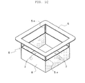
- FIGS. 1A - 1C illustrate a first preferred embodiment of the lighting apparatus.
- FIG. 1A is a sectional view showing a situation where a plane light-emitter is constituted by an organic EL element, and a lighting device body are attached to, for example, a ceiling side in order.
- FIG. 1B is a bottom plan view from below of the lighting apparatus.
- FIG. 1C is a perspective view from above of the lighting device body at some angle.
- a plane light-emitter 1 is constituted by the organic EL element formed in the shape of a rectangle.
- a fixing member 2 made of a metal material is attached so that four sides of the above-mentioned plane light-emitter 1 may be surrounded.
- an attachment side 4 such as a ceiling
- the above-mentioned attachment side 4 is provided, if needed, with an opening 4a through which an electric supply line (not shown) for supplying electric power to the above-mentioned organic EL element as the plane light-emitter 1 is threaded.
- the magnet sheet is used instead of the above-mentioned adhesive sheet 3, so that the plane light-emitter 1 can be attached to the above-mentioned attachment side 4 by means of the above-mentioned fixing member 2 which surrounds the four sides of the plane iighr-emitter 1.
- a lighting device body as indicated by reference numeral 5 is attached to the above-mentioned plane light-emitter 1 which is attached to the attachment side 4 as described above. As shown also in FIGS. 1B and 1C , this lighting device body 5 is provided with a lighting device attachment member 6 mounted to the plane light-emitter 1 so as to surround the luminescence side 1a of the above-mentioned plane light-emitter 1.
- This lighting device attachment member 6 is formed to have a rectangular opening and a size similar to that of the above-mentioned fixing member 2 attached so as to surround the four sides of the above-mentioned plane light-emitter 1. Therefore, by forming the lighting device attachment member 6 from a metal material, the lighting device body 5 can be attached to the fixing member 2 of the plane light-emitter 1 through a magnet sheet(a magnetic fixing means) as indicated by reference numeral 9 and having formed therein the rectangular opening.
- the above-mentioned lighting device body 5 has formed therein a first light guidance member 7 for passing the emitted light in a direction which does not intersect perpendicularly with the luminescence side 1a of the above-mentioned plane light-emitter 1.
- the first light guidance member 7 is constituted by window holes partitioned by four rib members 5a which connect the lighting device attachment member 6 with a second light guidance member 8 in the shape of a cylinder, as will be described later.
- the above-ment ioned second light guidance member 8 is constituted by a rectangular cylinder (indicated by the same reference numeral 8 as that of the second light guidance member), and functions to pass the emitted light which is directed toward the inside of the cylinder and is in a direction intersecting perpendicularly with the luminescence side 1a of the above-mentioned plane light-emitter 1.
- the above-mentioned cylinder 8 by forming the above-mentioned cylinder 8 to have a predetermined length, the light emitted from the above-mentioned plane light-emitter 1 is projected downward at a predetermined cutoff angle, and it acts so as to achieve the function as a down light.
- the above-mentioned lighting device body 5 is formed by bending a metal plate whose overall thickness is thin (for example, approximately 0.8 mum), and it is arranged to be subjected to baking finish with melamine resin, for example. Therefore, the lighting device body 5 can be formed to be lightweight, and as shown by way of illustration it can be detachably attached to the ceiling side etc. by means of the magnet sheet 9.
- FIG. 2 is for explaining an example of a structure of the organic EL element (indicated by the same reference numeral 1 as that of the plane light-emitter) as the above-mentioned plane light-emitter 1.
- FIG. 2 it is illustrated in a situation where respective layers constituting the organic EL element 1 are separated in a layer direction.
- a transparent electrode 1B made of ITO (for example) used as a first electrode is formed at one side of a substrate 1A formed of a transparent material, such as for example glass.
- an organic luminescence layer 1C is formed as a film so as to be stacked on the above-mentioned transparent electrode 1B.
- this organic luminescence layer is constituted by, for example, a hole transport layer, a luminescence layer, an electronic transport layer, etc., it is represented by the organic luminescence layer 1C with one layer in the drawing.
- a counter electrode 1D which serves as a second electrode and is made of aluminum etc., for example, is formed so as to be stacked on the above-mentioned organic luminescence layer 1C.
- a sealing substrate is disposed at the back side of the counter electrode 1D, and this sealing substrate is sealed by a sealing member at a circumferential edge of the above-mentioned glass substrate 1A on a front side.
- a direct-current power source E is connected between the above-mentioned transparent electrode 1B and the counter electrode 1D, whereby a portion sandwiched between the above-mentioned transparent electrode 1B and the counter electrode 10 at the organic luminescence layer 1C emits light which is conducted to the outside through the above-mentioned transparent electrode 18 and the glass substrate 1A.
- the above-mentioned organic EL element 1 is characterized in that it is driven by a low D/C voltage to provide high luminous efficiency and allow light weight and thinning and that heat is not substantially generated, thus being suitably applied to the lighting apparatus in accordance with the present invention.
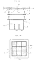
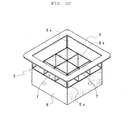
- FIGS. 3A - 3C show a second preferred embodiment of the lighting apparatus in accordance with the present invention.
- Each of these drawings is an illustration similar to that for the first preferred embodiment as already described with reference to FIGS. 1A - 1C .
- the same reference numerals are used for components that achieve the functions similar to those in the first preferred embodiment as described with reference to FIGS. 1A - 3C , therefore the detailed description will not be repeated.
- louvers 8a having formed thereon partitioning sides in the direction which intersects perpendicularly with the luminescence side 1a of the above-mentioned organic EL element 1 as the plane light-emitter are arranged in the rectangular cylinder 8 which constitutes the second light guidance member.
- the louvers 8a in this preferred embodiment are arranged such that the inside of the rectangular cylinder 8 is divided into nine parts as described in FIG. 4B .
- the light emitted from the above-mentioned organic EL element 1 as the plane light-emitter can be projected below at a narrower cutoff angle, and the function to illuminate the areas immediately below them in the shape of a spot with a smaller size can be provided.
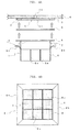
- FIGS. 4A - 4C show a third preferred embodiment of the lighting apparatus in accordance with the present invention.
- Each of these drawings is an illustration similar to that for the first or second preferred embodiment as already described with reference to FIGS. 1A - 1C or FIGS. 3A - 3C .
- the same reference numerals are used for components that achieve the functions similar to those in the first and second preferred embodiments, and therefore the detailed description will not be repeated.
- a reflection member 8b which deflects a part of light coming from the organic EL element 1 as the above-mentioned plane light-emitter is formed at an upper end of the cylinder 8 which constitutes the second light guidance member.
- the upper end of the above-mentioned cylinder 8 formed in the shape of a rectangle is formed to curve horizontally toward the outside of the cylinder 8, and a flange portion which is horizontally formed constitutes the above-mentioned reflection member 8b.
- FIG. 4A a part of light which is from the plane light-emitter 1 and passes through the second light guidance member 8 constituted by the window holes is reflected, as shown by arrow c, by the reflection member 8b formed in the shape of a flange, and is projected, as shown by arrow d, toward the attachment side 4 of the plane light-emitter 1. Therefore, in the case of attaching the lighting device body 5 to the ceiling side, a part of light from the plane light-emitter 1 reaches the ceiling side and can increase a degree of the indirect illumination.
- the lighting apparatus in accordance with the present invention is constituted by the plane light-emitter 1 and the lighting device body 5, and the above-mentioned lighting device body 5 is provided with the lighting device attachment member, the first light guidance member, and the second light guidance member, so that a part of light from the above-mentioned plane light-emitter is allowed to achieve the function to illuminate the lighting device attachment side (ceiling side) with the faint light and to have the function as the down light having a predetermined cutoff angle.
- the cylinder body which constitutes the second light guidance member in the lighting device body is made in the shape of a rectangle, it is possible to select, for example, a cylindrical shape or other shapes.
- the shape of the louvers may not be parallel crossed, but can be formed concentrically with the cylinder body, for example.
- the first light guidance member 7 is constituted by the window holes divided by the four rib members 5a which connect the lighting device attachment member 6 and the cylindrical second light guidance member 8, it can also be made of a light permeable material, such as for example Japanese paper or a synthetic resin, according to usage. Furthermore, it may also be arranged such that a plate-like light permeable member is fitted into the above-mentioned window hole.
- the plane light-emitter 1 of the lighting apparatus in accordance with the present invention is attached to the ceiling side and used as the down light
- this plane light-emitter 1 it is also possible to attach this plane light-emitter 1 to a wall surface (side wall). It is further possible to attach the above-mentioned plane light-emitter 1 to a tip of a support (for example), and to use it so as to function as a stand light or a spotlight.
- the organic EL element is desirably used as the plane light-emitter.
- a plane light-emitting element such as an inorganic EL element.
Landscapes
- Engineering & Computer Science (AREA)
- Physics & Mathematics (AREA)
- Microelectronics & Electronic Packaging (AREA)
- Optics & Photonics (AREA)
- General Engineering & Computer Science (AREA)
- Non-Portable Lighting Devices Or Systems Thereof (AREA)
- Electroluminescent Light Sources (AREA)
- Planar Illumination Modules (AREA)
Applications Claiming Priority (1)
| Application Number | Priority Date | Filing Date | Title |
|---|---|---|---|
| JP2008168799A JP4570668B2 (ja) | 2008-06-27 | 2008-06-27 | 照明装置 |
Publications (1)
| Publication Number | Publication Date |
|---|---|
| EP2138752A1 true EP2138752A1 (fr) | 2009-12-30 |
Family
ID=40940130
Family Applications (1)
| Application Number | Title | Priority Date | Filing Date |
|---|---|---|---|
| EP09163881A Withdrawn EP2138752A1 (fr) | 2008-06-27 | 2009-06-26 | Appareil d'éclairage |
Country Status (4)
| Country | Link |
|---|---|
| US (1) | US20090323349A1 (fr) |
| EP (1) | EP2138752A1 (fr) |
| JP (1) | JP4570668B2 (fr) |
| CN (1) | CN101614338A (fr) |
Families Citing this family (9)
| Publication number | Priority date | Publication date | Assignee | Title |
|---|---|---|---|---|
| AU2011243504B2 (en) * | 2010-04-23 | 2015-09-17 | Opto Design, Inc. | Surface illumination fixture and surface illumination device |
| US8668361B2 (en) | 2010-09-22 | 2014-03-11 | Bridgelux, Inc. | LED-based replacement for fluorescent light source |
| CN102242895A (zh) * | 2011-07-07 | 2011-11-16 | 周陈华 | 一种便于安装及更换灯泡的射灯 |
| KR101277635B1 (ko) * | 2011-10-06 | 2013-06-21 | 심상미 | 조명장치 |
| KR101514114B1 (ko) * | 2012-09-14 | 2015-04-21 | 주식회사 엘지화학 | Oled 조명 모듈 |
| CN103775909A (zh) * | 2012-10-24 | 2014-05-07 | 海洋王照明科技股份有限公司 | 地埋灯 |
| JP2015083283A (ja) * | 2013-10-25 | 2015-04-30 | 京セラ株式会社 | 光照射モジュールおよび印刷装置 |
| US10443794B2 (en) * | 2016-12-02 | 2019-10-15 | Kaneka Corporation | Planar light source and illumination apparatus |
| JP7511210B2 (ja) * | 2019-10-18 | 2024-07-05 | 株式会社キルトプランニングオフィス | 照明システム |
Citations (8)
| Publication number | Priority date | Publication date | Assignee | Title |
|---|---|---|---|---|
| JPH0547208A (ja) | 1991-08-09 | 1993-02-26 | Matsushita Electric Works Ltd | ダウンライト |
| JPH09293410A (ja) | 1996-04-30 | 1997-11-11 | Matsushita Electric Works Ltd | ダウンライト |
| US6565231B1 (en) * | 2002-05-28 | 2003-05-20 | Eastman Kodak Company | OLED area illumination lighting apparatus |
| EP1367677A2 (fr) * | 2002-05-28 | 2003-12-03 | Eastman Kodak Company | Dispositif d'éclairage avec une oled flexible comme source lumineuse |
| EP1367676A1 (fr) * | 2002-05-28 | 2003-12-03 | Eastman Kodak Company | Dispositif électroluminescent organique ayant un substrat flexible sur un support |
| EP1431656A2 (fr) * | 2002-12-18 | 2004-06-23 | General Electric Company | Luminaire avec extraction de lumière d'une source lumineuse plane |
| DE202006005427U1 (de) * | 2006-04-04 | 2006-06-08 | Emde, Thomas | Beleuchtungsvorrichtung |
| JP2007095394A (ja) | 2005-09-27 | 2007-04-12 | Matsushita Electric Works Ltd | ダウンライト |
Family Cites Families (10)
| Publication number | Priority date | Publication date | Assignee | Title |
|---|---|---|---|---|
| US2147482A (en) * | 1936-12-01 | 1939-02-14 | Gen Electric | Luminaire |
| US2540389A (en) * | 1946-02-21 | 1951-02-06 | Elwood Wiles | Signal light ray director |
| JPS6178004A (ja) * | 1984-09-25 | 1986-04-21 | 松下電工株式会社 | 照明器具 |
| JPH07201212A (ja) * | 1993-12-28 | 1995-08-04 | Mitsubishi Electric Corp | 照明器具 |
| JP3806963B2 (ja) * | 1996-01-25 | 2006-08-09 | 松下電工株式会社 | 照明器具 |
| FR2806648B1 (fr) * | 2000-03-22 | 2002-08-23 | Visteon Systemes Interieurs | Procede et dispositif de formation d'une piece planiforme notamment destinee a l'equipement interieur de vehicule automobile |
| US7048425B2 (en) * | 2003-09-29 | 2006-05-23 | Dialight Corporation | LED signal with side emitting status indicators |
| US20060017059A1 (en) * | 2004-07-21 | 2006-01-26 | Eastman Kodak Company | Packaged OLED light source |
| EP1891476B1 (fr) * | 2005-05-30 | 2012-12-19 | Koninklijke Philips Electronics N.V. | Dispositif electroluminescent a couche d'amelioration de la luminosite |
| JP4702063B2 (ja) * | 2006-01-11 | 2011-06-15 | パナソニック電工株式会社 | 発光パネルユニット |
-
2008
- 2008-06-27 JP JP2008168799A patent/JP4570668B2/ja not_active Expired - Fee Related
-
2009
- 2009-06-26 EP EP09163881A patent/EP2138752A1/fr not_active Withdrawn
- 2009-06-26 CN CN200910146286A patent/CN101614338A/zh active Pending
- 2009-06-26 US US12/492,287 patent/US20090323349A1/en not_active Abandoned
Patent Citations (8)
| Publication number | Priority date | Publication date | Assignee | Title |
|---|---|---|---|---|
| JPH0547208A (ja) | 1991-08-09 | 1993-02-26 | Matsushita Electric Works Ltd | ダウンライト |
| JPH09293410A (ja) | 1996-04-30 | 1997-11-11 | Matsushita Electric Works Ltd | ダウンライト |
| US6565231B1 (en) * | 2002-05-28 | 2003-05-20 | Eastman Kodak Company | OLED area illumination lighting apparatus |
| EP1367677A2 (fr) * | 2002-05-28 | 2003-12-03 | Eastman Kodak Company | Dispositif d'éclairage avec une oled flexible comme source lumineuse |
| EP1367676A1 (fr) * | 2002-05-28 | 2003-12-03 | Eastman Kodak Company | Dispositif électroluminescent organique ayant un substrat flexible sur un support |
| EP1431656A2 (fr) * | 2002-12-18 | 2004-06-23 | General Electric Company | Luminaire avec extraction de lumière d'une source lumineuse plane |
| JP2007095394A (ja) | 2005-09-27 | 2007-04-12 | Matsushita Electric Works Ltd | ダウンライト |
| DE202006005427U1 (de) * | 2006-04-04 | 2006-06-08 | Emde, Thomas | Beleuchtungsvorrichtung |
Also Published As
| Publication number | Publication date |
|---|---|
| US20090323349A1 (en) | 2009-12-31 |
| CN101614338A (zh) | 2009-12-30 |
| JP4570668B2 (ja) | 2010-10-27 |
| JP2010009969A (ja) | 2010-01-14 |
Similar Documents
| Publication | Publication Date | Title |
|---|---|---|
| EP2138752A1 (fr) | Appareil d'éclairage | |
| CN102933898B (zh) | 照明装置 | |
| CN102563408B (zh) | 照明装置 | |
| JP5601556B2 (ja) | 照明装置および照明器具 | |
| EP2280213B1 (fr) | Dispositif d'éclairage | |
| JP5071745B2 (ja) | 照明装置 | |
| JP6063926B2 (ja) | 照明器具 | |
| JP5217789B2 (ja) | 照明器具 | |
| JP6931809B2 (ja) | 照明器具 | |
| JP5732613B2 (ja) | 照明器具 | |
| JP2013186981A (ja) | Led照明器具 | |
| KR20110076247A (ko) | Led 조명장치 | |
| JP5592528B1 (ja) | 看板用照明装置 | |
| JP2010164810A (ja) | 照明装置 | |
| JP3193001U (ja) | Led照明器具 | |
| JP2013025868A (ja) | 照明装置 | |
| JP2011054351A (ja) | 照明装置 | |
| JP3211593U (ja) | 薄板状のled照明器具 | |
| JP5887506B2 (ja) | 発光装置および照明装置 | |
| JP5927534B2 (ja) | 発光装置および照明器具 | |
| CN102781807A (zh) | 电梯的轿厢内照明装置 | |
| JP2018137069A (ja) | 照明器具 | |
| KR102033302B1 (ko) | Led 고효율 구조를 갖는 조명 장치 | |
| JP3133014U (ja) | 内照式看板用led照明ユニット、及び内照式看板 | |
| JP2018186006A (ja) | 照明装置 |
Legal Events
| Date | Code | Title | Description |
|---|---|---|---|
| PUAI | Public reference made under article 153(3) epc to a published international application that has entered the european phase |
Free format text: ORIGINAL CODE: 0009012 |
|
| AK | Designated contracting states |
Kind code of ref document: A1 Designated state(s): AT BE BG CH CY CZ DE DK EE ES FI FR GB GR HR HU IE IS IT LI LT LU LV MC MK MT NL NO PL PT RO SE SI SK TR |
|
| 17P | Request for examination filed |
Effective date: 20100608 |
|
| STAA | Information on the status of an ep patent application or granted ep patent |
Free format text: STATUS: THE APPLICATION HAS BEEN WITHDRAWN |
|
| 18W | Application withdrawn |
Effective date: 20130618 |